Comparative Study on the Interest in Non-Uniform Rational B-Splines Representation versus Polynomial Surface Description in a Freeform Three-Mirror Anastigmat

 , , , ,
Abstract
:1. Introduction
2. Materials and Methods
- Differential ray tracing, which simultaneously computes the rays and their derivatives when tracing them. A ray is defined as a line perpendicular to a wavefront and can be represented by a point and a normalized direction vector. Rays being reflected and refracted by the optical surfaces form the ray path, which does not necessarily have an explicit analytical expression. In FORMIDABLE, differential ray tracing is implemented in two ways: using implicit differentiation applied to the calculation of the intersection between a ray and a surface or using the differentiation of the offense to the Fermat path principle [24].
- Merit function differentiation, using Automatic Differentiation (AD) [27].
- Projected apertures, which can be used to define an aperture on NURBS surfaces, whereas optical design software usually only consider surfaces that are defined with a sag. The projected aperture is defined on a plane in front of the NURBS that is projected on it.
- Ray aiming, which allows the aperture stop to be placed at any desired location. It is implemented using black-box algorithms in commercial optical design software and might not be considered in FANO. FORMIDABLE performs ray aiming using an algorithm in three steps. The algorithm finds the on-axis chief ray (OAR) and computes the physical pupil of the system, which then allows the computation of a raymap through backward propagation. These points intersect the pupil at the correct position but do not originate from the correct points in the field of view (FOV). Ray tracing from the correct field points is achieved through direct propagation and uses the rays in the raymap as guesses to find the ray that intersects the pupil at the correct location. Then, non-physical rays are eliminated.
- Use of external optimizers. Tests have shown that the Levenberg–Marquart algorithm performed well on optical systems. We used the open source implementation from the SciPy library [28].
- Pupil sampling corresponds to the number and repartition of rays used to sample the pupil of the system. We used rectangular array sampling with 21 × 21 points for FORMIDABLE, which requires an odd value to sample the center of the pupil. The closest attainable values with OpticStudio were either 20 × 20 or 22 × 22. Both were tested, and the values yielding the best optimization results were kept (20 × 20). The difference between both these settings was marginal.
- Field sampling corresponds to the number and the repartition of point sources in the FOV. We used rectangular array sampling with 5 × 5 points.
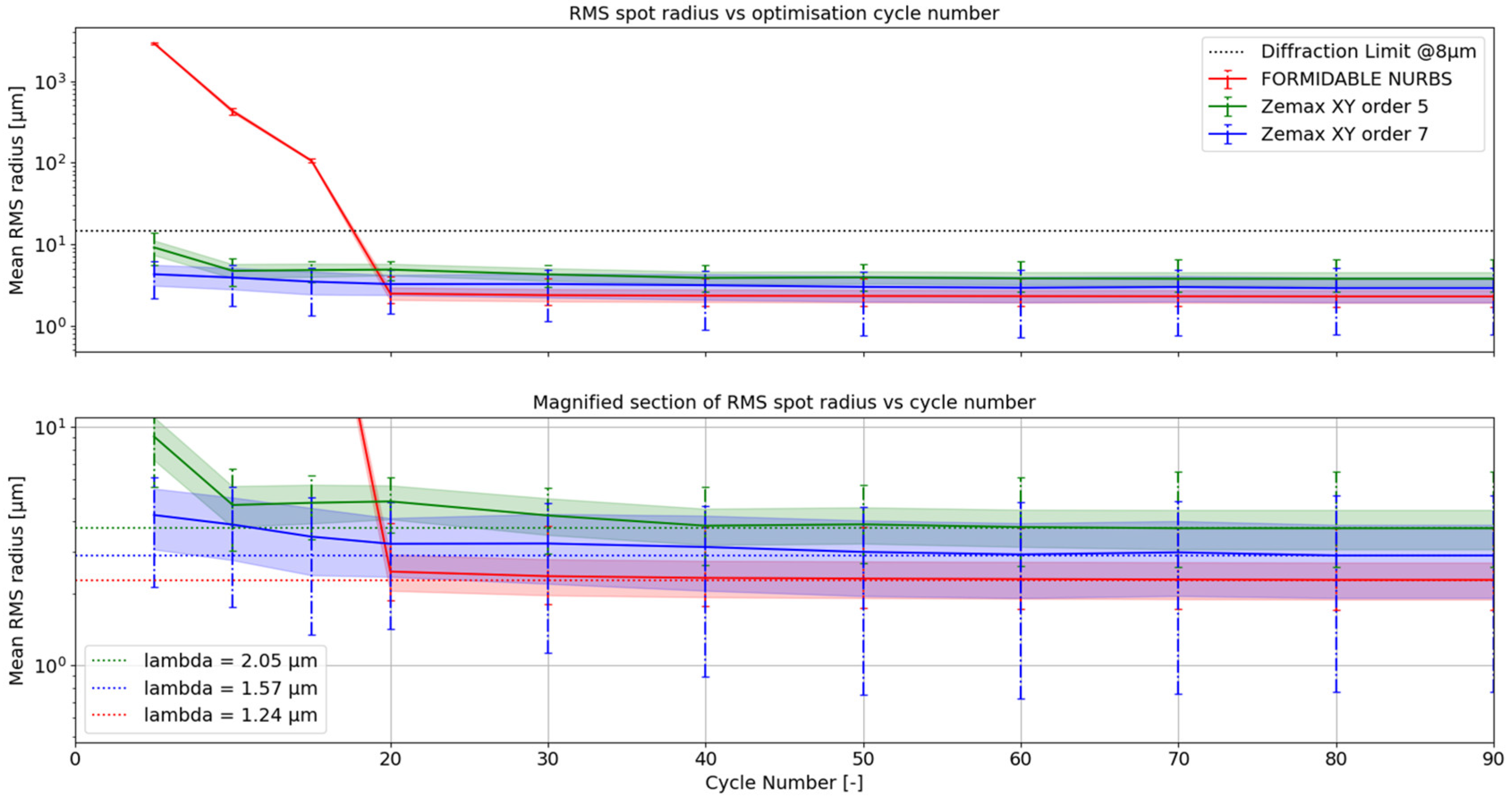
- The optimization criterion corresponds to the OpticStudio Default Merit Function Start (DMFS) operand, which can be set in the Optimization Wizard. Standard criteria include spot the radius or the wavefront error. We chose to optimize over the root mean square (RMS) spot radius. In FORMIDABLE, the equivalent setting is called “TransverseAberration”.
- The first one allows the focal length of the system to be maintained. In OpticStudio, the EFFL operand can be used for centered optical systems. However, it cannot be used for off-axis systems, and such an operand was not implemented in FORMIDABLE. We thus minimized the distance between the position of the real centroids and those given by the following equation for eight points at the edges of the FOV and an additional one at the center of the FOV:
- The second operand allows the ray clearance of the system to be defined in order to avoid vignetting. The implementation of the RayClearance operand in FORMIDABLE is based on the JMRCC operand in CodeV [29]. The geometry of the NURBS system is frozen by guaranteeing that the ray clearances keep their respective values at the beginning of the optimization. A similar implementation was carried out in OpticStudio using the RAGY, RAGX, RAGB, and RAGC operands as well as simple mathematical operations. In the systems optimized with OpticStudio, the surfaces’ positions and orientations were not used as variables.
3. Results
3.1. Systematic Approach
3.2. Detailed Comparison between NURBS and Polynomial TMA
4. Discussion
5. Conclusions
Author Contributions
Funding
Institutional Review Board Statement
Informed Consent Statement
Data Availability Statement
Acknowledgments
Conflicts of Interest
References
- Rolland, J.P.; Davies, M.A.; Suleski, T.J.; Evans, C.; Bauer, A.; Lambropoulos, J.C.; Falaggis, K. Freeform Optics for Imaging. Optica 2021, 8, 161. [Google Scholar] [CrossRef]
- Schiesser, E.M.; Bauer, A.; Rolland, J.P. Effect of Freeform Surfaces on the Volume and Performance of Unobscured Three Mirror Imagers in Comparison with Off-Axis Rotationally Symmetric Polynomials. Opt. Express 2019, 27, 21750–21765. [Google Scholar] [CrossRef] [PubMed]
- González-Acuña, R.G. Design of a Pair of Aplanatic Mirrors. Appl. Opt. 2022, 61, 1982–1986. [Google Scholar] [CrossRef] [PubMed]
- Duerr, F.; Thienpont, H. “First Time Right”—Calculating Imaging Systems from Scratch-INVITED. EPJ Web Conf. 2021, 255, 02001. [Google Scholar] [CrossRef]
- Volatier, J.-B.; Druart, G. Differential Method for Freeform Optics Applied to Two-Mirror off-Axis Telescope Design. Opt. Lett. 2019, 44, 1174–1177. [Google Scholar] [CrossRef] [PubMed]
- Benitez, P.; Minano, J.C.; Blen, J.; Mohedano, R.; Chaves, J.; Dross, O.; Hernandez, M.; Alvarez, J.L.; Falicoff, W. SMS Design Method in 3D Geometry: Examples and Applications. Nonimaging Optics: Maximum Efficiency Light Transfer VII; SPIE: San Francisco, Philippines, 2004; Volume 5185, pp. 18–29. [Google Scholar]
- Mayeur, T.; Volatier, J.-B.; Druart, G.; Cau, F.; Tartas, E.; Durand, A. Automatic Method of Exploring the Landscape of Freeform Dioptric Optical Problems, Working in the Infrared Region. Optics 2023, 4, 482–499. [Google Scholar] [CrossRef]
- Yang, S.; Hu, D.; Wang, A. Point-by-Point Fabrication and Characterization of Sapphire Fiber Bragg Gratings. Opt. Lett. 2017, 42, 4219–4222. [Google Scholar] [CrossRef] [PubMed]
- Yang, T.; Zhu, J.; Wu, X.; Jin, G. Direct Design of Freeform Surfaces and Freeform Imaging Systems with a Point-by-Point Three-Dimensional Construction-Iteration Method. Opt. Express 2015, 23, 10233–10246. [Google Scholar] [CrossRef] [PubMed]
- Zhang, X.-Y.; Yu, Y.-S.; Chen, C.; Zhu, C.-C.; Yang, R.; Liu, Z.-J.; Liang, J.-F.; Chen, Q.-D.; Sun, H.-B. Point-by-Point Dip Coated Long-Period Gratings in Microfibers. IEEE Photonics Technol. Lett. 2014, 26, 2503–2506. [Google Scholar] [CrossRef]
- Mao, B.; Yang, T.; Xu, H.; Chen, W.; Cheng, D.; Wang, Y. FreeformNet: Fast and Automatic Generation of Multiple-Solution Freeform Imaging Systems Enabled by Deep Learning. Photon. Res. 2023, 11, 1408–1422. [Google Scholar] [CrossRef]
- Thompson, K.P.; Fuerschbach, K.; Schmid, T.; Rolland, J.P. Using Nodal Aberration Theory to Understand the Aberrations of Multiple Unobscured Three Mirror Anastigmatic (TMA) Telescopes; Sasián, J., Youngworth, R.N., Eds.; SPIE: San Diego, CA, USA, 2009; p. 74330B. [Google Scholar]
- Sasián, J. Theory of Sixth-Order Wave Aberrations. Appl. Opt. 2010, 49, D69–D95. [Google Scholar] [CrossRef] [PubMed]
- Houllier, T.; Lépine, T. Comparing Optimization Algorithms for Conventional and Freeform Optical Design. Opt. Express 2019, 27, 18940–18957. [Google Scholar] [CrossRef] [PubMed]
- Sahin, F.E. Open-Source Optimization Algorithms for Optical Design. Optik 2019, 178, 1016–1022. [Google Scholar] [CrossRef]
- Nijkerk, M.D.; Gruber, J.M.; Boonacker, B. Freeform Optics Design Tool for Compact Spectrometers. In Proceedings of the International Conference on Space Optics—ICSO 2018, Chania, Greece, 9–12 October 2018; Volume 11180, pp. 780–788. [Google Scholar]
- Héron, S.; Semet, Y.; Barrère, R.; Lee, M.-S.-L.; Loiseaux, B. Automated Design of Freeform Off-Axis Three-Mirrors-Anastigmat. Imaging Systems and Applications; Optica Publishing Group: Seattle, WA, USA, 2022; p. IW3C.2. [Google Scholar]
- Muslimov, E.; Hugot, E.; Jahn, W.; Vives, S.; Ferrari, M.; Chambion, B.; Henry, D.; Gaschet, C. Combining Freeform Optics and Curved Detectors for Wide Field Imaging: A Polynomial Approach over Squared Aperture. Opt. Express 2017, 25, 14598–14610. [Google Scholar] [CrossRef] [PubMed]
- Duveau, L. Freeform Mirror Designs for Aerospatial Multi Spectral Band Imaging Systems. Ph.D Thesis, Université de Lyon, Lyon, France, 2022. [Google Scholar]
- Brömel, A. Development and Evaluation of Freeform Surface Descriptions; Friedrich-Schiller-Universität Jena: Jena, Germany, 2018. [Google Scholar]
- Houllier, T. Optical Imaging Systems with Freeform Surfaces: Optimization Algorithms Study and Freeform Surfaces Metrology. Ph.D Thesis, Université de Lyon, Lyon, France, 2021. [Google Scholar]
- Chrisp, M.P. New Freeform NURBS Imaging Design Code. Classical Optics 2014; Optica Publishing Group: Koala Coast, HA, USA, 2014; p. ITh3A.7. [Google Scholar]
- Fast Accurate NURBS Optimization (FANO)—Sc22. Available online: https://sc22.mghpcc.org/project/fast-accurate-nurbs-optimization-fano/ (accessed on 14 June 2024).
- Volatier, J.-B.; Beaussier, S.J.; Druart, G.; Jougla, P.; Keller, F. Implementation of FORMIDABLE: A Generalized Differential Optical Design Library with NURBS Capabilities. J. Eur. Opt. Soc.-Rapid Publ. 2024, 20, 2. [Google Scholar] [CrossRef]
- ESSR—License European Space Agency Community License—v2.4 Strong Copyleft (Type 1). Available online: https://essr.esa.int/license/european-space-agency-community-license-v2-4-strong-copyleft-type-1 (accessed on 14 June 2024).
- Formidable/Formidable GitLab. Available online: https://gitlab.space-codev.org/formidable/formidable (accessed on 14 June 2024).
- Baydin, A.G.; Pearlmutter, B.A.; Radul, A.A.; Siskind, J.M. Automatic Differentiation in Machine Learning: A Survey. arXiv 2015. [Google Scholar] [CrossRef]
- Moré, J.J. The Levenberg-Marquardt Algorithm: Implementation and Theory. In Numerical Analysis; Watson, G.A., Ed.; Lecture Notes in Mathematics; Springer: Berlin/Heidelberg, Germany, 1978; Volume 630, pp. 105–116. ISBN 978-3-540-08538-6. [Google Scholar]
- Rodgers, J.M. Control of Packaging Constraints in the Optimization of Unobscured Reflective Systems; SPIE: Los Angeles, CA, USA, 1987; p. 143. [Google Scholar]
- Reshidko, D.; Sasian, J. Method for the Design of Nonaxially Symmetric Optical Systems Using Free-Form Surfaces. Opt. Eng. 2018, 57, 101704, Erratum in Opt. Eng. 2021, 60, 119801. [Google Scholar] [CrossRef]
- Piegl, L.; Tiller, W. The NURBS Book; Springer Science & Business Media: Berlin, Germany, 2012; ISBN 3-642-59223-6. [Google Scholar]
- Freslier, C.; Druart, G.; Fontbonne, A.; Lépine, T.; Keller, F.; Buisset, C.; Agocs, T.; Hélière, A.; Volatier, J.-B.; Beaussier, S.; et al. Optimization of a Freeform TMA with a Differential Ray Tracer with NURBS Capabilities. Optical Design and Engineering IX; Babington, J., Lépine, T., Gross, H., Eds.; SPIE: Strasbourg, France, 2024; p. 24. [Google Scholar]
- Kopon, D.; Montague, J.; Primeau, B.; Krastev, P.; Cappiello, G.; Johnson, J. Sensitivity Comparison of a NURBS Freeform Telescope. Optomechanical Engineering 2023; SPIE: Strasbourg, France, 2023; Volume 12669, pp. 122–131. [Google Scholar]
- Chrisp, M.P.; Primeau, B.; Echter, M.A. Imaging Freeform Optical Systems Designed with NURBS Surfaces. Opt. Eng. 2016, 55, 071208. [Google Scholar] [CrossRef]


| Parameter | TMA |
|---|---|
| Focal length [] | |
| Field of view | 4.4 × 3.3 |
| Stop location | |
| Aperture semi-diameter [] | 22.235 |
| 1.5 |
| MF Parameter | FORMIDABLE | OpticStudio |
|---|---|---|
| Pupil Sampling Type | Rectangular Array | Rectangular Array |
| Pupil Sampling Value | 21 × 21 | 20 × 20 |
| Field Sampling Type | Rectangular Array | Rectangular Array |
| Field Sampling Value | 5 × 5 | 5 × 5 |
| Optimization Criterion | TransverseAberration | Spot (TRCX/TRCY) |
| Focal Length Operands | centroid_goals | CENX/CENY |
| Ray Clearance Operands | RayClearance | RAGY/RAGX/RAGB/RAGC |
| Optimization Case | NURBS | XY5 | XY7 |
|---|---|---|---|
| Number of Degrees of Freedom | 216 | 30 | 54 |
| Mirror | NURBS | XY5 | XY7 |
|---|---|---|---|
| M1 | 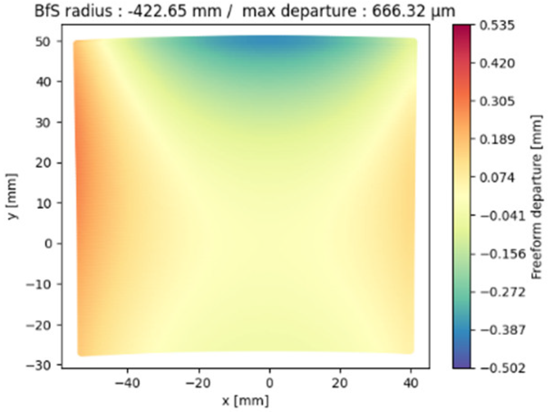 | 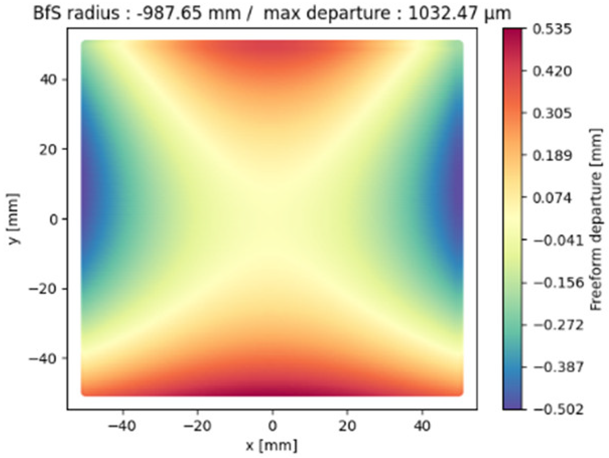 | 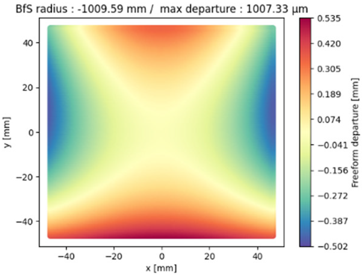 |
| M2 |  |  |  |
| M3 | 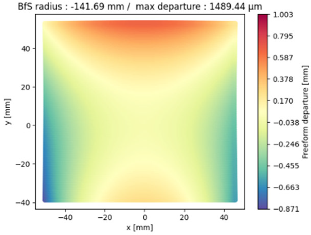 | 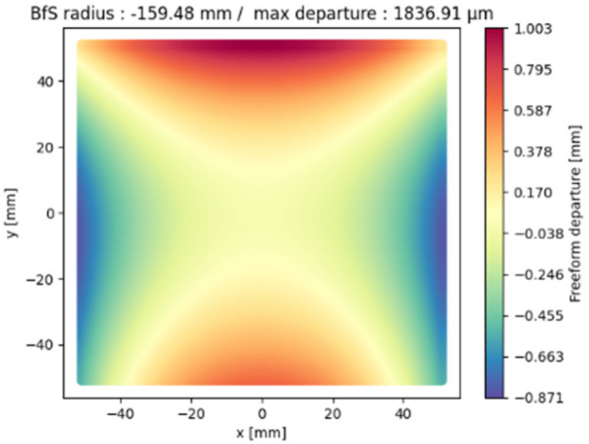 |  |
| NURBS | XY5 | XY7 | |
|---|---|---|---|
| M1 | −422.65 | −987.65 | −1014.58 |
| M2 | −117.23 | −211.27 | −213.86 |
| M3 | −141.69 | −159.48 | −160.13 |
| RMS Freeform Deviation | NURBS | XY5 | XY7 |
| M1 | 116.5 | 217.8 | 242.2 |
| M2 | 237.7 | 308.0 | 320.0 |
| M3 | 264.9 | 367.1 | 375.6 |
| Average | 206.4 | 297.6 | 312.6 |
Disclaimer/Publisher’s Note: The statements, opinions and data contained in all publications are solely those of the individual author(s) and contributor(s) and not of MDPI and/or the editor(s). MDPI and/or the editor(s) disclaim responsibility for any injury to people or property resulting from any ideas, methods, instructions or products referred to in the content. |
© 2024 by the authors. Licensee MDPI, Basel, Switzerland. This article is an open access article distributed under the terms and conditions of the Creative Commons Attribution (CC BY) license (https://creativecommons.org/licenses/by/4.0/).
Share and Cite
Freslier, C.; Druart, G.; Fontbonne, A.; Lépine, T.; Buisset, C.; Agocs, T.; Heliere, A.; Keller, F.; Volatier, J.-B.; Beaussier, S.; et al. Comparative Study on the Interest in Non-Uniform Rational B-Splines Representation versus Polynomial Surface Description in a Freeform Three-Mirror Anastigmat. Photonics 2024, 11, 875. https://doi.org/10.3390/photonics11090875
Freslier C, Druart G, Fontbonne A, Lépine T, Buisset C, Agocs T, Heliere A, Keller F, Volatier J-B, Beaussier S, et al. Comparative Study on the Interest in Non-Uniform Rational B-Splines Representation versus Polynomial Surface Description in a Freeform Three-Mirror Anastigmat. Photonics. 2024; 11(9):875. https://doi.org/10.3390/photonics11090875
Chicago/Turabian StyleFreslier, Clément, Guillaume Druart, Alice Fontbonne, Thierry Lépine, Christophe Buisset, Tibor Agocs, Arnaud Heliere, Fanny Keller, Jean-Baptiste Volatier, Stéphane Beaussier, and et al. 2024. "Comparative Study on the Interest in Non-Uniform Rational B-Splines Representation versus Polynomial Surface Description in a Freeform Three-Mirror Anastigmat" Photonics 11, no. 9: 875. https://doi.org/10.3390/photonics11090875
APA StyleFreslier, C., Druart, G., Fontbonne, A., Lépine, T., Buisset, C., Agocs, T., Heliere, A., Keller, F., Volatier, J.-B., Beaussier, S., & Jougla, P. (2024). Comparative Study on the Interest in Non-Uniform Rational B-Splines Representation versus Polynomial Surface Description in a Freeform Three-Mirror Anastigmat. Photonics, 11(9), 875. https://doi.org/10.3390/photonics11090875