Article

Optical Manipulation of Fibroblasts with Femtosecond Pulse and CW Laser

1
Institute of Laser & Micro/Nano Engineering, Sichuan University, Chengdu 610065, China
2
College of Computer Science, Sichuan University, Chengdu 610065, China
*
Author to whom correspondence should be addressed.
Photonics 2024, 11(3), 248; https://doi.org/10.3390/photonics11030248
Submission received: 23 December 2023 / Revised: 8 February 2024 / Accepted: 11 February 2024 / Published: 11 March 2024
(This article belongs to the Special Issue Technologies and Applications of Biophotonics)

Abstract

:
Using tight focusing light, optical tweezers (OT) are tools that can manipulate and capture microscopic particles and biological cells as well as characterize a wide range of micro and nanomaterials. In this paper, we focused on fibroblasts, which are widely used in the biomedical area for a variety of purposes, including promoting human wound healing and preventing the early proliferation of tumor cells. We first built an optical tweezer experimental platform, using an 808 nm continuous-wave laser as the capture light source, to confirm that the device can precisely control the movement of single or multiple particles as well as fibroblasts. Then, a 1030 nm femtosecond laser was employed as the capture light source to study the manipulation of microparticles and fibroblasts at different powers. Lastly, a protracted manipulation protocol was used to prevent the fibroblasts from adhering to the wall. This method can be used to isolate and precisely block adherent growth of fibroblasts in cell populations. This experimental result can be further extended to other biological cells.

1. Introduction

In the field of biomedical research, the study of biological tissue cells has long been a focus. At the moment, optical tweezer (OT) technology has emerged as an efficient tool for biological cell research, including immunological interactions and early disease diagnosis [1,2,3]. As early as 1619, Kepler recognized the ability of light to exert forces on matter when he described the deflection of the comet’s tail [4]. Nevertheless, the effects of these forces were so negligible that they were considered irrelevant for any practical application [4,5]. Until 1970, Arthur Ashkin demonstrated that optical forces can be used to manipulate microscopic particles and individual atoms by altering their motions [6,7,8]. This technology has been developed into optical tweezers [9,10], which are now widely used in various research fields, such as micro/nano fabrication and assembly [11], microfluidic flow manipulation [12], cell classification [13], tissue engineering [14] and intercellular interaction [15]. Compared with traditional mechanical force, optical force has the characteristics of non-contact, non-invasive, fast responding, and strong controllability [5,16,17]. Over the past few decades, optical tweezers have attracted great interest due to their potential applications in biomedicine and biophysics, especially in monomolecular and cell manipulation [18,19,20]. Examples include the study of the elastic properties and biological properties of DNA molecules [21], the molecular characterization of protein folding [22], and the elastic and viscoelastic properties of cellular or subcellular structures [23]. In addition, a number of impressive studies, including the manipulation of red blood cells within the capillaries of living animals [24], the measurement of intercellular adhesion and anti-adhesion forces [25], and the use of lipid droplets as endogenous intracellular microlenses for real-time monitoring of subcellular structures and extracellular signals [26], have also been realized based on optical tweezers. As a result of scientific and technological advances, various kinds of optical tweezers, such as holographic optical tweezers [27], plasmonic optical tweezers [28], fiber optical tweezers [29], and optothermal tweezers [30], have demonstrated the ability to manipulate particles or cells directly or indirectly utilizing optical forces and energy [31].
In this work, the manipulation of polystyrene (PS) particles and fibroblasts was performed using a designed optical tweezer system, and the quantitative analysis of laser power and target movement speed was conducted. In Section 2, the schematic diagram of the experimental platform for laser manipulation of the target and the simulation of the light field and optical force was illustrated. In Section 3, first an 808 nm continuous-wave laser was utilized as the capture light source to manipulate the two-dimensional or three-dimensional rotation motion of single and multiple PS particles. Second, a 1030 nm femtosecond pulse laser was used as the capture light source to manipulate particles and cells at different powers. It was found in the experiments that, at higher laser power (higher than 2.5 mW and 12 mW for PS particles and fibroblasts, respectively), bubbles were generated on the surface of the targets near the focal point due to the larger thermal gradient force. And subsequently, the collapse of the bubbles caused the microspheres and fibroblasts to produce undirected displacements, while the fibroblasts were damaged. At a relatively low laser power (lower than 2.5 mW and 11.5 mW laser power for PS particles and fibroblasts, respectively), the stable manipulation of PS particles and fibroblasts was performed. At last, we exhaustively examined the greatest speed at which the two light sources can be stabilized to manipulate particles and cells at different powers. Additionally, fibroblasts often grow mixed with tumor cells at the same time, making it difficult to purify tumor cells, and fibroblasts usually inhibit the growth of early tumor cells [32]. Therefore, removal of fibroblasts is the key to tumor cell culture. Long-term manipulation (not less than 25 min) of fibroblasts was experimentally demonstrated to delay the adherent growth of fibroblasts without affecting the normal growth of other cells not irradiated by the laser in the culture dish. This experiment showed that precise control of the time of cell adherence growth could be realized.

2. Materials and Methods

2.1. Experimental Setup and Materials

As can be seen in Figure 1, an optical tweezer system was designed, and the sample stage and microscopic imaging part of an ordinary inverted microscope was utilized. Two different light sources were used, including an 808 nm continuous-wave laser (fiber-coupled output continuous-wave laser, Beijing Honglan Optoelectronics, Beijing, China) and a 1030 nm femtosecond laser (290 fs, 1030 nm, 1 MHz, 100 µJ, Hangzhou Yacto Technology, Hangzhou, China). In order to make the optical path easy to adjust, compact, and cost-effective, the L1 and L2 lens sets were used as well the adjustment mirrors to match the beam to the rear pupil of the microscope and the well position to the imaging plane to capture and aim at the target object. In addition, the L1 and L2 lens sets were also used as the beam parallel adjustment. The dashed box is the location of the power detector. A 12.5 µL volume of PS microspheres with a diameter of 10 µm (produced by Tianjin BaseLine Chrom Technology Research Center, Tianjin, China) were homogeneously dispersed in 4 mL of deionized water as the target for optical trapping experiments. In addition, we also cultured mouse fibroblasts (NIH 3T3) as the target of this study. The cells were cultured in a 25 mL culture flask with culture medium added and placed in a carbon dioxide incubator at 37 °C. The cell culture medium was composed of 89% Dulbecco’s Modified Eagle Medium/F12(DMEM/F12) Medium with 1% penicillin-streptomycin and 10% fetal bovine serum added. Before the experiment, the cells were digested with trypsin for 3 min to suspend them, and the digestion was stopped by adding the culture medium. The fibroblasts were then transferred to a centrifuge tube and centrifuged for 5 min, then the suspension was poured out, culture medium was added to the centrifuge tube, and the cells were dispersed and resuspended with a pipette gun. Finally, fibroblasts suspended in culture medium were used for capture experiments.

2.2. Electromagnetic Theory Model

In this paper, the Lorentz force of an electromagnetic field acting on particles in the electromagnetic model is utilized to study the light force on particles. The optical force acting on the microsphere has been calculated numerically using Maxwell stress tensors, defined as [33]:
T = ε 0 [ E E + c 2 B B 1 2 ( E · E + c 2 B · B ) I ]
where ε 0 denotes the dielectric constant of the target object, E is the electric field intensity, B is the magnetic induction intensity, c is the speed of light in vacuum, and I represents the unit tensor.
The simulation model based on the electromagnetic field momentum conservation law and the finite element method was performed with COMSOL software (COMSOL Multiphysics® 5.6, COMSOL Inc., Shinagawa City, Tokyo). The optical force was calculated by integrating the Maxwell tensor in Equation (1) over the line of particles, as given by [4,28,34,35]:
V f d V + d d t V j d V = V · T d V = S T · d S
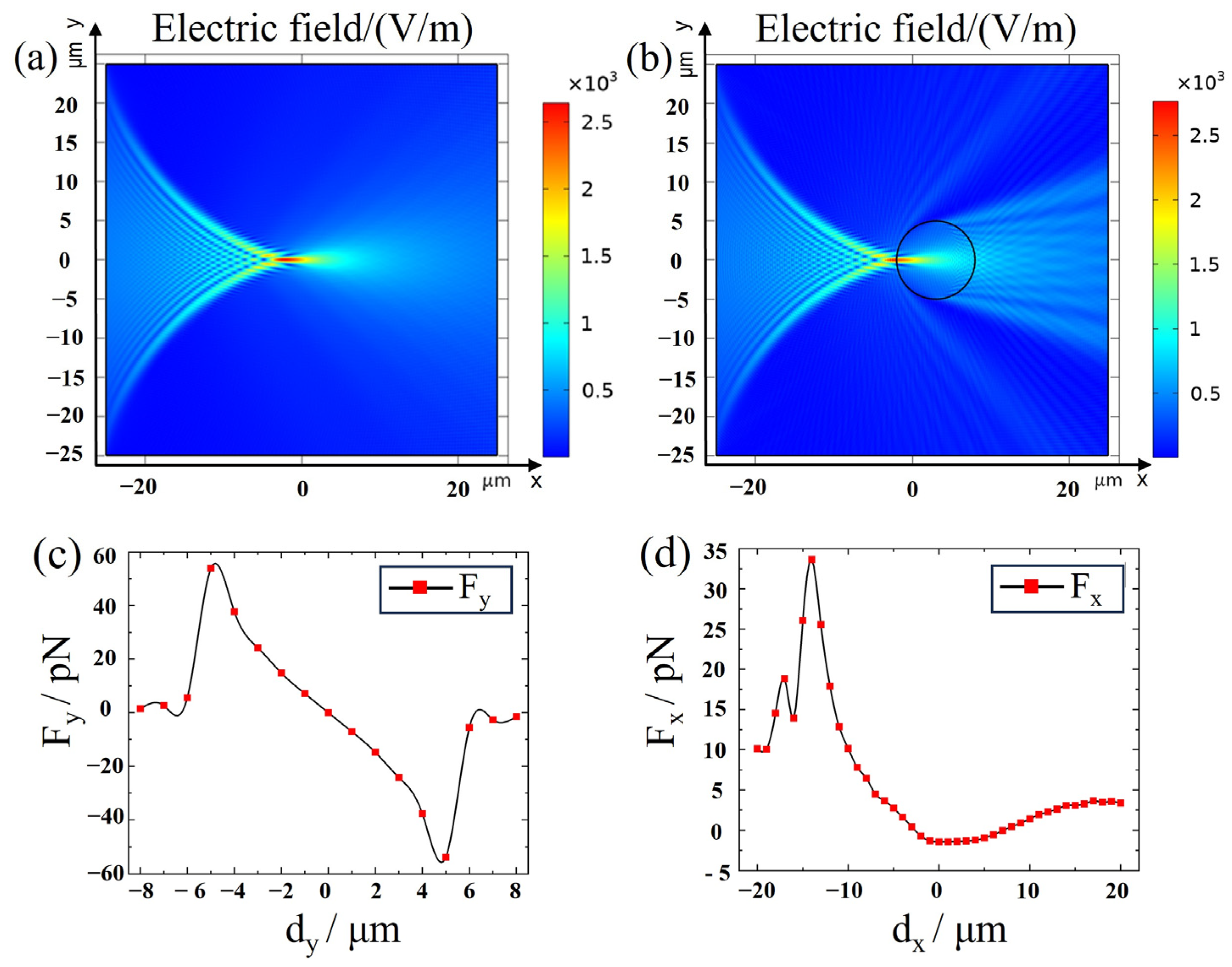
where f denotes the momentum density of the charge system; j represents the change rate of the momentum density of the electromagnetic field; and T is the momentum flow density tensor of the electromagnetic field, or the electromagnetic field stress tensor. The area integral represents the momentum flow from surface S of the scattering particles into the V region. When the electromagnetic field is stably distributed, the second term on the left side of Equation (1) is zero. The total force of the electromagnetic field acting in the V region is equal to the area integral of the Maxwell stress tensor at the interface [36,37]. Figure 2 shows the light field distribution and optical force of light capture on the two-dimensional plane. The incident light wavelength is 808 nm, and the direction of incidence is along the x-axis. Figure 2a,b represent the electric field distribution near the focus of the 808 nm laser with and without PS particles, respectively. Figure 2c,d represent the optical trapping force of the particles along the y and x directions, respectively. The horizontal axis dy and dx are the distances between the microsphere center and the laser focus along the y and x directions, respectively. Both Figure 2c,d indicated that there was a trapping force acting on the microsphere near the laser focus.

3. Results and Discussion

3.1. Capturing Objects with 808 nm CW Laser

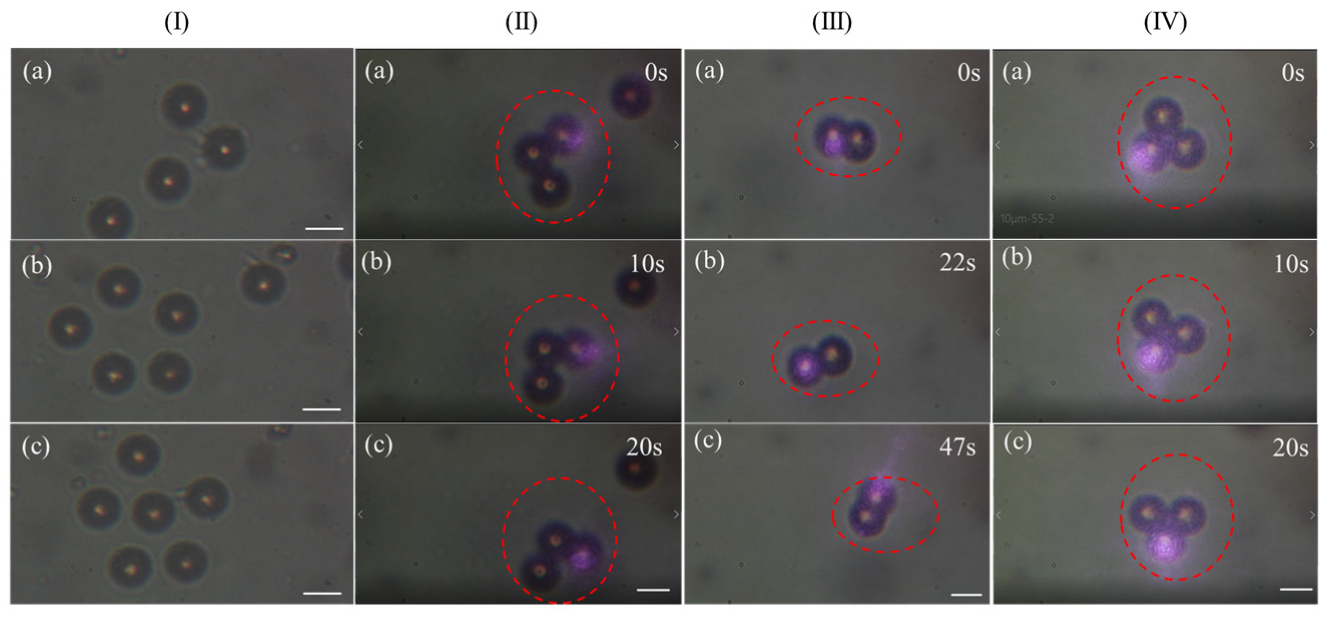
The optical tweezer system we designed was able to experiment with different laser sources. Firstly, an 808 nm fiber laser was used as the capture light source and a few drops of evenly distributed PS solution was dropped on the glass slide, adjusting the lens to move the laser spot to the vicinity of the particles. The particles would be attracted to the center of the spot, and the experimental results showed that the time for the particles to be attracted to the center of the spot decreased as the power increased. The laser power was measured at the position before the beam entering the objective lens, as the dashed box in Figure 1. When the power was between 12 mW and 40 mW, the device could stably manipulate the PS particles to move in a directional manner, and the speed of movement of the microspheres increased with increasing power. As shown in Figure 3I, we manipulated individual particles to form different shapes, such as the number “7” (Figure 3Ia), “hollow pentagon” (Figure 3Ib), and “solid pentagon” (Figure 3Ic). In addition, the movement of a multi-particle group was also achieved with our optical tweezer system, as shown in Figure 3. The figure shows the process of manipulating a multi-particle group to rotate in different directions. The red dotted circle is the controlled particles. Figure 3II–IV represent clockwise rotation, counterclockwise rotation and directional movement, and counterclockwise rotation of particles in a two-dimensional plane, respectively. Arbitrary rotation and movement of the multi-particle group was demonstrated with our experimental configuration.
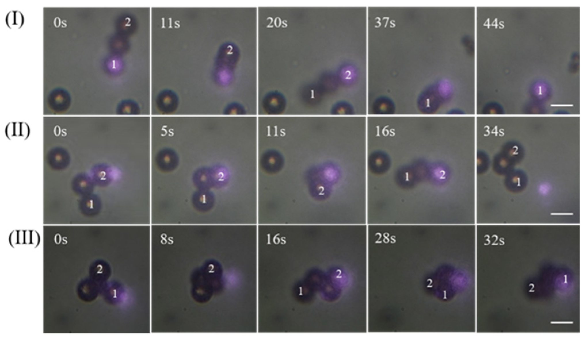
When the power was greater than 40 mW, the rotation and displacement of a multi-particle group in three-dimensional space were achieved. The captured PS particles were pushed away from the focal plane position after being sucked into the laser focus, as shown in Figure 4. The numbers marked on each particle in the figure represent the position change of the particles during the rotation. When the PS particles were close to the focus, the surface absorbed heat energy unevenly, which caused the thermal gradient generated by the absorption of heat energy in the surrounding environment to be much weaker than that generated by the non-uniform absorption of heat energy on the PS particle surface. Therefore, the direction of the thermal gradient force pointed away from the center of the well. PS particles moved to the well center under the influence of the optical gradient force; when the PS particle was close enough to the well center, it was repelled by the strong thermal gradient force and scattering force, causing it to leave the well center [38]. It can be seen from Figure 4 that the multi-particle group near the laser spot was first sucked into the focus. At this time, the particles were subjected to a large repulsion force, so that the particles at the spot were pushed away from the focal plane to rotate. By slightly moving the spot to another particle near the focal plane, the particles were sucked into the spot and then pushed away from the focal plane. Repeating this process, it was possible to manipulate the multi-particle group for three-dimensional rotation and displacement.

3.2. Capturing Objects with 1030 nm Femtosecond Pulse Laser

We further used the 1030 nm femtosecond laser as a light source to manipulate the target object. Fibroblasts play an important role in the repair of human wounds and bones, so we chose fibroblasts with diameters of about 10 to 20 μm as capture targets. The temperature of the medium in the fibroblast trapping experiments was about 28 °C. Table 1 lists in detail the maximum velocities of the two capture laser sources for stable manipulation of microparticles and cells at different laser powers. We used a stepper motor that could operate at a stable and uniform speed to control the translation platform and achieve uniform motion of the captured target. By adjusting the number of input pulses per second to the stepper motor at different laser powers, the maximum speed to stabilize the control target at that power was obtained. The capture experiments were performed with PS particles uniformly dispersed in deionized water and fibroblasts suspended in the culture medium. The refractive indices of PS particles and deionized water were about 1.6 and 1.333, respectively, the relative refractive index was about 1.200. In the experiments using cells as objects, the refractive indices of the fibroblasts and culture medium were about 1.375 [39] and 1.337 [40], so the relative refractive index was about 1.028. As can be seen from the table, since the relative refractive index of the cells and the culture medium was smaller than that of the PS particles and the deionized water, the power required to capture the cell was much larger than that required to capture the PS particles. Compared with 808 nm laser capture, the power of the 1030 nm femtosecond laser to capture and manipulate fibroblasts was almost an order of magnitude lower, but the speed was greater. Therefore, using a 1030 nm femtosecond laser to manipulate and study biological cells caused less damage to the sample [41].
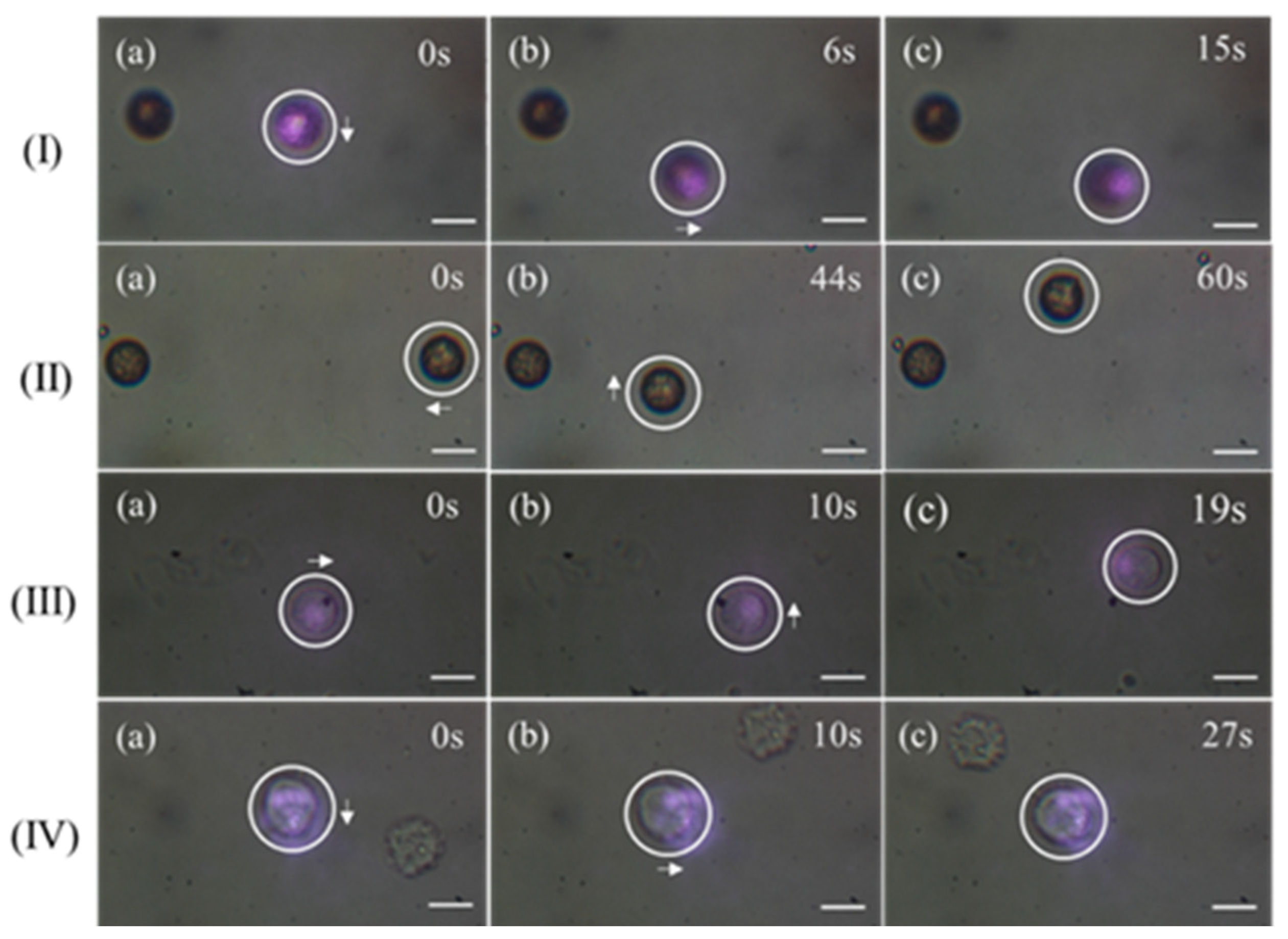
Besides using the motor to control the moving speed, the mean velocity of manually moving the laser focus to maneuver the target was calculated by recording video. A Matlab script (Matlab R2020b, MathWorks. Inc., Natick, MA 01760, USA) was programmed based on the Horn–Schuck method to analyze the moving target in videos. The capture process is shown in Figure 5. The white circle indicates the position of the target we were stabilizing for manipulation. Figure 5I,II show the directional displacement of PS particles manipulated using 808 nm and 1030 nm lasers, respectively. Figure 5III,IV show the directional movement of fibroblasts manipulated with 808 nm and 1030 nm lasers, respectively. According to the experimental observation results, the average velocities of PS particles were calculated to be 3.3 μm/s and 2.7 μm/s, respectively, and the average velocities of manipulated fibroblasts were 1.4 μm/s and 2.5 μm/s, respectively. This was consistent with the speeds in Table 1.
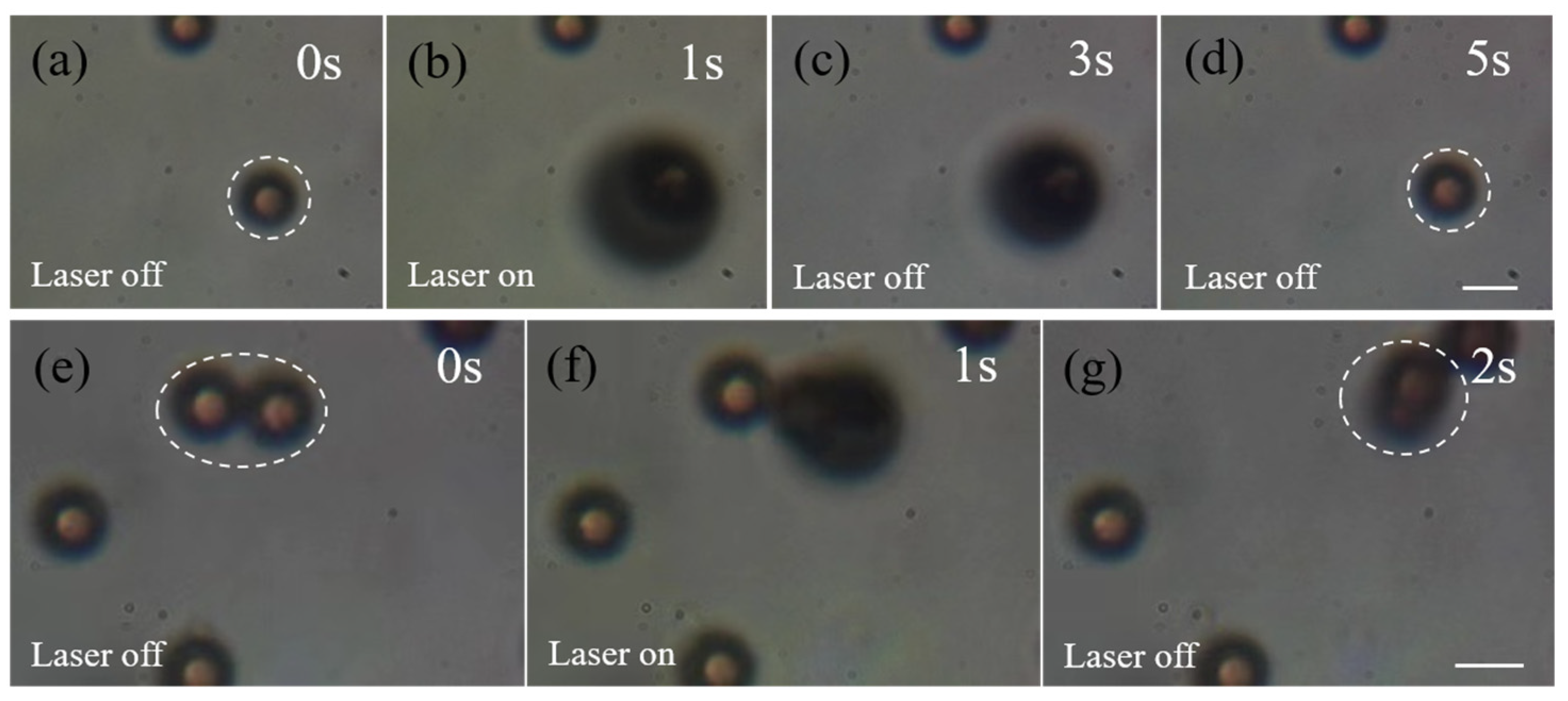
Capture and manipulation could be achieved with a 1030 nm femtosecond pulsed laser at much lower laser power than with an 808 nm laser. A laser power of 1 mW with the 1030 nm laser was sufficient to stabilize the manipulation of PS particles, whereas the minimum power required for stable manipulation of PS particles using an 808 nm laser was about 15 mW. And the velocity of the particles manipulated by the femtosecond laser was about 2.34 μm/s, which was greater than that of the 808 nm. Accordingly, the minimum power of the 1030 nm pulsed laser for stable manipulation of fibroblasts was much less than that of the 808 nm laser for cell manipulation, but the speed of fibroblasts manipulated by the 1030 nm laser was faster than that of fibroblasts manipulated by the 808 nm laser. It was found that when the laser power was greater than 12 mW, bubbles were instantaneously generated on the surface of the fibroblasts, which could increase to tens of micrometers in diameter, and the bubbles gradually shrank when the laser was turned off. For PS particles, similar processes were observed at powers above 3 mW. It was found that the cell membranes of fibroblasts may be broken, while PS particles were hardly damaged after repeating laser irradiation several times, as shown in Figure 6a–d. In addition, the shrinkage of the bubbles caused the particles to be pushed away from their original positions with extremely fast speed, as shown in Figure 6e,f. The direction and velocity of the push caused by bubbles was related to the size and position of the bubble, and the directed manipulation of the target object was expected by studying the bubble dynamics [42]. The white virtual coils indicate the particles at the laser focus. It can be assumed that this experiment was conducive to the parallel manipulation of multiple particles in a large volume, providing a method for microfluids optical micromanipulation and cavitation-assisted drug delivery [43].
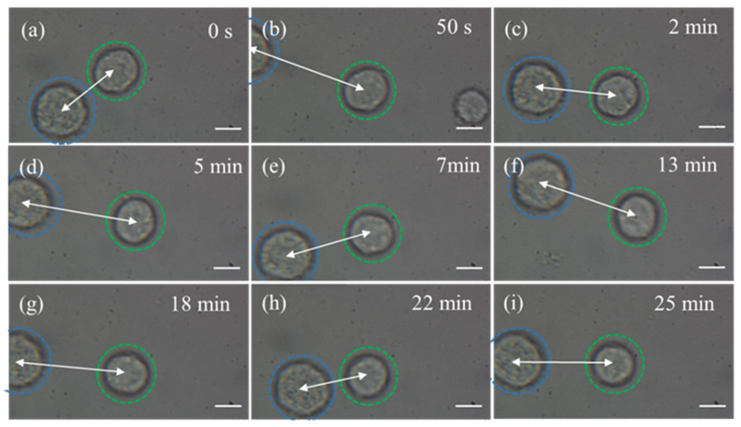
Next, we demonstrate experiments utilizing a 1030 nm femtosecond pulsed laser for continuous manipulation of fibroblasts to delay their adherent growth. The position and orientation of the target cell (green dashed circle) relative to the reference cell (blue dashed circle) is shown in Figure 7. Our experimental device was able to migrate the target cells in an arbitrary direction for a long period of time. The white arrows show the changes in the relative positions of the two cells over time, while the reference cell did not produce displacement. It is clear that continuous manipulation of fibroblasts inhibited their adherent growth for a prolonged period of time, and thus can be used to study the characterization of cell membranes, cell attachment, and growth processes. In addition, the experiment could also achieve precise removal of one or more of the cells suspended in vitro without affecting other cells.

4. Conclusions

In this paper, an experimental platform based on optical force effects was built, which can be widely used with various laser sources to conduct manipulation experiments at low cost. The experiments to capture and manipulate 10 μm diameter PS particles and fibroblasts were performed. The velocity and laser power of the captured targets were quantitatively analyzed. When the 808 nm laser power was between 62 mW and 92 mW, the fibroblasts could be stably manipulated, whereas this was achieved with the 1030 nm laser between 4 mW and 12 mW laser power. When the 1030 nm laser power was greater than 12 mW, bubbles were generated when the laser spot was focused near the fibroblasts, and the bubbles drove the target to move quickly during the collapse process. For PS particles, bubbles were generated when the 1030 nm laser power was greater than 2.5 mW. In addition, continuous manipulation experiments were conducted on fibroblasts to delay their adherence, indicating that cell adherent growth was controllable. With the help of optical force manipulation, cell sorting can be achieved during cell culture, such as removing small amounts of suspended fibroblasts in tumor cell culture.

Supplementary Materials

The following supporting information can be downloaded at: https://www.mdpi.com/article/10.3390/photonics11030248/s1, Video S1: The process of the 808 nm laser manipulating the movement and three-dimensional rotation of the ‘one-shaped’ multi-particle group. Video S2: The process of the 808 nm laser manipulating the motion and three-dimensional rotation of the ‘angular’ multi-particle group. Video S3: The process of the 808 nm laser manipulating the movement and three-dimensional rotation of the ‘cone’ multi-particle group. Video S4: Manipulation of fibroblast movement induced by 808 nm continuous-wave laser. Video S5: The 1030 nm femtosecond laser manipulation of fibroblast movement.

Author Contributions

Conceptualization, X.Z. and G.F.; methodology, X.Z.; software, X.Z., S.C. and Y.W.; validation, X.Z. and Y.W.; formal analysis, X.Z.; investigation, X.Z.; resources, X.Z. and G.F.; data curation, X.Z.; writing—original draft preparation, X.Z.; writing—review and editing, X.Z., Y.W. and S.C.; visualization, X.Z.; supervision, G.F.; project administration, G.F.; funding acquisition, G.F. All authors have read and agreed to the published version of the manuscript.

Funding

This research was supported by the National Key Research and Development Program of China under Grant No. 2022YFB3606300, the National Natural Science Foundation of China under Grant No. U2230129, International Science and Technology Cooperation Projects funded by the Chengdu Municipal Government (No. 2022-GH02-00017-HZ), and International Cooperation Projects of Sichuan Province (No. 2023YFH0094).

Institutional Review Board Statement

Not applicable.

Informed Consent Statement

Not applicable.

Data Availability Statement

The code for this paper is available and already uploaded to GitHub, and can be downloaded from https://github.com/guoxingx/experimental_data (accessed on 15 February 2024).

Acknowledgments

We thank the West China Hospital of Sichuan University for providing mouse fibroblasts, and thanks to the above funding support.

Conflicts of Interest

The authors have no relevant financial interests in the paper and no other potential conflicts of interest to disclose.

References

  1. Lu, F.; Gong, L.; Kuai, Y.; Tang, X.; Xiang, Y.; Wang, P.; Zhang, D. Controllable Optofluidic Assembly of Biological Cells Using an All-Dielectric One-Dimensional Photonic Crystal. Photonics Res. 2021, 10, 14–20. [Google Scholar] [CrossRef]
  2. Berghoff, K.; Gross, W.; Eisentraut, M.; Kress, H. Using Blinking Optical Tweezers to Study Cell Rheology During Initial Cell-Particle Contact. Biophys. J. 2021, 120, 3527–3537. [Google Scholar] [CrossRef] [PubMed]
  3. Corsetti, S.; Dholakia, K. Optical manipulation: Advances for biophotonics in the 21st century. J. Biomed. Opt. 2021, 26, 070602. [Google Scholar] [CrossRef] [PubMed]
  4. Pesce, G.; Jones, P.H.; Maragò, O.M.; Volpe, G. Optical Tweezers: Theory and Practice. Eur. Phys. J. Plus 2020, 135, 949. [Google Scholar] [CrossRef]
  5. Maragò, O.M.; Jones, P.H.; Gucciardi, P.G.; Volpe, G.; Ferrari, A.C. Optical Trapping and Manipulation of Nanostructures. Nat. Nanotechnol. 2013, 8, 807–819. [Google Scholar] [CrossRef] [PubMed]
  6. Ashkin, A. Acceleration and Trapping of Particles by Radiation Pressure. Phys. Rev. Lett. 1970, 24, 156–159. [Google Scholar] [CrossRef]
  7. Ashkin, A. Atomic-Beam Deflection by Resonance-Radiation Pressure. Phys. Rev. Lett. 1970, 25, 1321–1324. [Google Scholar] [CrossRef]
  8. Ashkin, A. History of Optical Trapping and Manipulation of Small-Neutral Particle, Atoms, and Molecules. IEEE J. Sel. Top. Quantum Electron. 2000, 6, 841–856. [Google Scholar] [CrossRef]
  9. Melzer, J.E.; McLeod, E. Fundamental Limits of Optical Tweezer Nanoparticle Manipulation Speeds. ACS Nano 2018, 12, 2440–2447. [Google Scholar] [CrossRef]
  10. Hoshina, M.; Yokoshi, N.; Ishihara, H. Nanoscale Rotational Optical Manipulation. Opt. Express 2020, 28, 14980–14993. [Google Scholar] [CrossRef]
  11. Gould, O.E.C.; Qiu, H.; Lunn, D.J.; Rowden, J.; Harniman, R.L.; Hudson, Z.M.; Winnik, M.A.; Miles, M.J.; Manners, I. Transformation and Patterning of Supermicelles Using Dynamic Holographic Assembly. Nat. Commun. 2015, 6, 10009. [Google Scholar] [CrossRef]
  12. Li, Y.; Ren, Y.; Qi, H.; Ruan, L. Manipulation of Microscale Fluid Using Laser-Irradiated Nanoparticle Arrays. Plasmonics 2019, 14, 1555–1563. [Google Scholar] [CrossRef]
  13. Wang, X.; Chen, S.; Kong, M.; Wang, Z.; Costa, K.D.; Li, R.A.; Sun, D. Enhanced Cell Sorting and Manipulation with Combined Optical Tweezer and Microfluidic Chip Technologies. Lab A Chip 2011, 11, 3656–3662. [Google Scholar] [CrossRef]
  14. Mirsaidov, U.; Scrimgeour, J.; Timp, W.; Beck, K.; Mir, M.; Matsudaira, P.; Timp, G. Live Cell Lithography: Using Optical Tweezers to Create Synthetic Tissue. Lab A Chip 2008, 8, 2174–2181. [Google Scholar] [CrossRef]
  15. Rouger, V.; Bordet, G.; Couillault, C.; Monneret, S.; Mailfert, S.; Ewbank, J.J.; Pujol, N.; Marguet, D. Independent Synchronized Control and Visualization of Interactions between Living Cells and Organisms. Biophys. J. 2014, 106, 2096–2104. [Google Scholar] [CrossRef]
  16. Zhang, Y.; Li, Y.; Zhang, Y.; Hu, C.; Liu, Z.; Yang, X.; Zhang, J.; Yang, J.; Yuan, L. HACF-Based Optical Tweezers Available for Living Cells Manipulating and Sterile Transporting. Opt. Commun. 2018, 427, 563–566. [Google Scholar] [CrossRef]
  17. Bai, J.; Ge, C.-X.; Wu, Z.-S. Optical Trapping of Chiral Particles by Dual Laser Beams. Photonics 2023, 10, 905. [Google Scholar] [CrossRef]
  18. Xiang, Y.; Tang, X.; Min, C.; Rui, G.; Kuai, Y.; Lu, F.; Wang, P.; Ming, H.; Zhan, Q.; Yuan, X.; et al. Optical Trapping with Focused Surface Waves. Ann. Der Phys. 2020, 532, 1900497. [Google Scholar] [CrossRef] [PubMed]
  19. Zhang, J.; Lu, F.; Zhang, W.; Yu, W.; Zhu, W.; Premaratne, M.; Mei, T.; Xiao, F.; Zhao, J. Optical Trapping of Single Nano-Size Particles Using a Plasmonic Nanocavity. J. Phys. Condens. Matter 2020, 32, 475301. [Google Scholar] [CrossRef] [PubMed]
  20. Sarshar, M.; Wong, W.T.; Anvari, B. Comparative study of methods to calibrate the stiffness of a single-beam gradient-force optical tweezers over various laser trapping powers. J. Biomed. Opt. 2014, 19, 115001. [Google Scholar] [CrossRef] [PubMed]
  21. van Mameren, J.; Gross, P.; Farge, G.; Hooijman, P.; Modesti, M.; Falkenberg, M.; Wuite, G. Unraveling the structure of DNA during overstretching by using multicolor, single-molecule fluorescence imaging. Proc. Natl. Acad. Sci. USA 2009, 106, 18231–18236. [Google Scholar] [CrossRef]
  22. Bustamante, C.; Alexander, L.; Maciuba, K.; Kaiser, C.M. Single-Molecule Studies of Protein Folding with Optical Tweezers. Annu. Rev. Biochem. 2020, 89, 443–470. [Google Scholar] [CrossRef] [PubMed]
  23. Schreiner, S.M.; Koo, P.K.; Zhao, Y.; Mochrie, S.G.J.; King, M.C. The tethering of chromatin to the nuclear envelope supports nuclear mechanics. Nat. Commun. 2015, 6, 7159. [Google Scholar] [CrossRef]
  24. Zhong, M.-C.; Wei, X.-B.; Zhou, J.-H.; Wang, Z.-Q.; Li, Y.-M. Trapping red blood cells in living animals using optical tweezers. Nat. Commun. 2013, 4, 1768. [Google Scholar] [CrossRef]
  25. Jing, P.; Liu, Y.; Keeler, E.G.; Cruz, N.M.; Freedman, B.S.; Lin, L.Y. Optical tweezers system for live stem cell organization at the single-cell level. Biomed. Opt. Express 2018, 9, 771–779. [Google Scholar] [CrossRef] [PubMed]
  26. Chen, X.; Wu, T.; Gong, Z.; Guo, J.; Liu, X.; Zhang, Y.; Li, Y.; Ferraro, P.; Li, B. Lipid droplets as endogenous intracellular microlenses. Light Sci. Appl. 2021, 10, 242. [Google Scholar] [CrossRef] [PubMed]
  27. Chen, H.-C.; Cheng, C.-J. Holographic Optical Tweezers: Techniques and Biomedical Applications. Appl. Sci. 2022, 12, 10244. [Google Scholar] [CrossRef]
  28. Ren, Y.; Chen, Q.; He, M.; Zhang, X.; Qi, H.; Yan, Y. Plasmonic Optical Tweezers for Particle Manipulation: Principles, Methods, and Applications. ACS Nano 2021, 15, 6105–6128. [Google Scholar] [CrossRef]
  29. Li, K.; Wang, R.; Shao, S.; Xie, F.; Jiang, Y.; Xie, S. Capture Dynamics of Dielectric Microparticles in Hollow-Core-Fiber-Based Optical Traps. Photonics 2023, 10, 1154. [Google Scholar] [CrossRef]
  30. Ding, H.; Chen, Z.; Ponce, C.; Zheng, Y. Optothermal rotation of micro-/nano-objects. Chem. Commun. 2023, 59, 2208–2221. [Google Scholar] [CrossRef]
  31. Lin, L.; Peng, X.; Wei, X.; Mao, Z.; Xie, C.; Zheng, Y. Thermophoretic Tweezers for Low-Power and Versatile Manipulation of Biological Cells. ACS Nano 2017, 11, 3147–3154. [Google Scholar] [CrossRef] [PubMed]
  32. Delinassios, J.G.; Hoffman, R.M. The cancer-inhibitory effects of proliferating tumor-residing fibroblasts. Biochim. Et Biophys. Acta (BBA)-Rev. Cancer 2022, 1877, 188673. [Google Scholar] [CrossRef] [PubMed]
  33. Wang, S.B.; Chan, C.T. Lateral Optical Force on Chiral Particles Near a Surface. Nat. Commun. 2014, 5, 3307. [Google Scholar] [CrossRef] [PubMed]
  34. Li, H.; Ren, Y.; Li, Y.; He, M.; Gao, B.; Qi, H. Nanoparticle manipulation using plasmonic optical tweezers based on particle sizes and refractive indices. Opt. Express 2022, 30, 34092–34105. [Google Scholar] [CrossRef] [PubMed]
  35. Borghese, F.; Denti, P.; Saija, R.; Lati, M.A. Optical trapping of nonspherical particles in the T-matrix formalism. Opt. Express 2007, 15, 11984–11998. [Google Scholar] [CrossRef] [PubMed]
  36. Zhongfu, W.; Zhihai, L.; Chengkai, G.; Jun, Y.; Libo, Y. Numerical Simulation and Experiments of Two Fiber Optical Tweezers. Acta Opt. Sin. 2008, 28, 1971–1976. [Google Scholar] [CrossRef]
  37. Minjun, Y.; Wei, Z.; Wuzhou, S. Photothermal Effect Based Single Fiber Trapping Method and Simulation Analysis. Chin. J. Lasers 2019, 46, 216–223. [Google Scholar] [CrossRef]
  38. Zhong, M.-C.; Liu, A.-Y.; Ji, F. Opto-thermal oscillation and trapping of light absorbing particles. Opt. Express 2019, 27, 29730–29737. [Google Scholar] [CrossRef]
  39. Kemmler, M.; Fratz, M.; Giel, D.M.; Saum, N.; Brandenburg, A.; Hoffmann, C. Noninvasive time-dependent cytometry monitoring by digital holography. J. Biomed. Opt. 2007, 12, 064002. [Google Scholar] [CrossRef]
  40. Calabuig, A.; Mugnano, M.; Miccio, L.; Grilli, S.; Ferraro, P. Investigating fibroblast cells under “safe” and “injurious” blue-light exposure by holographic microscopy. J. Biophotonics 2016, 10, 919–927. [Google Scholar] [CrossRef]
  41. Mao, F.-L.; Xing, Q.-R.; Wang, K.; Lang, L.-Y.; Wang, Z.; Chai, L.; Wang, Q.-Y. Optical trapping of red blood cells and two-photon excitation-based photodynamic study using a femtosecond laser. Opt. Commun. 2005, 256, 358–363. [Google Scholar] [CrossRef]
  42. Carmona-Sosa, V.; Quinto-Su, P.A. Transient trapping of two microparticles interacting with optical tweezers and cavitation bubbles. J. Opt. 2016, 18, 105301. [Google Scholar] [CrossRef]
  43. Shakhov, A.; Astafiev, A.; Nadtochenko, V. Microparticle manipulation using femtosecond photonic nanojet-assisted laser cavitation. Opt. Lett. 2018, 43, 1858–1861. [Google Scholar] [CrossRef] [PubMed]
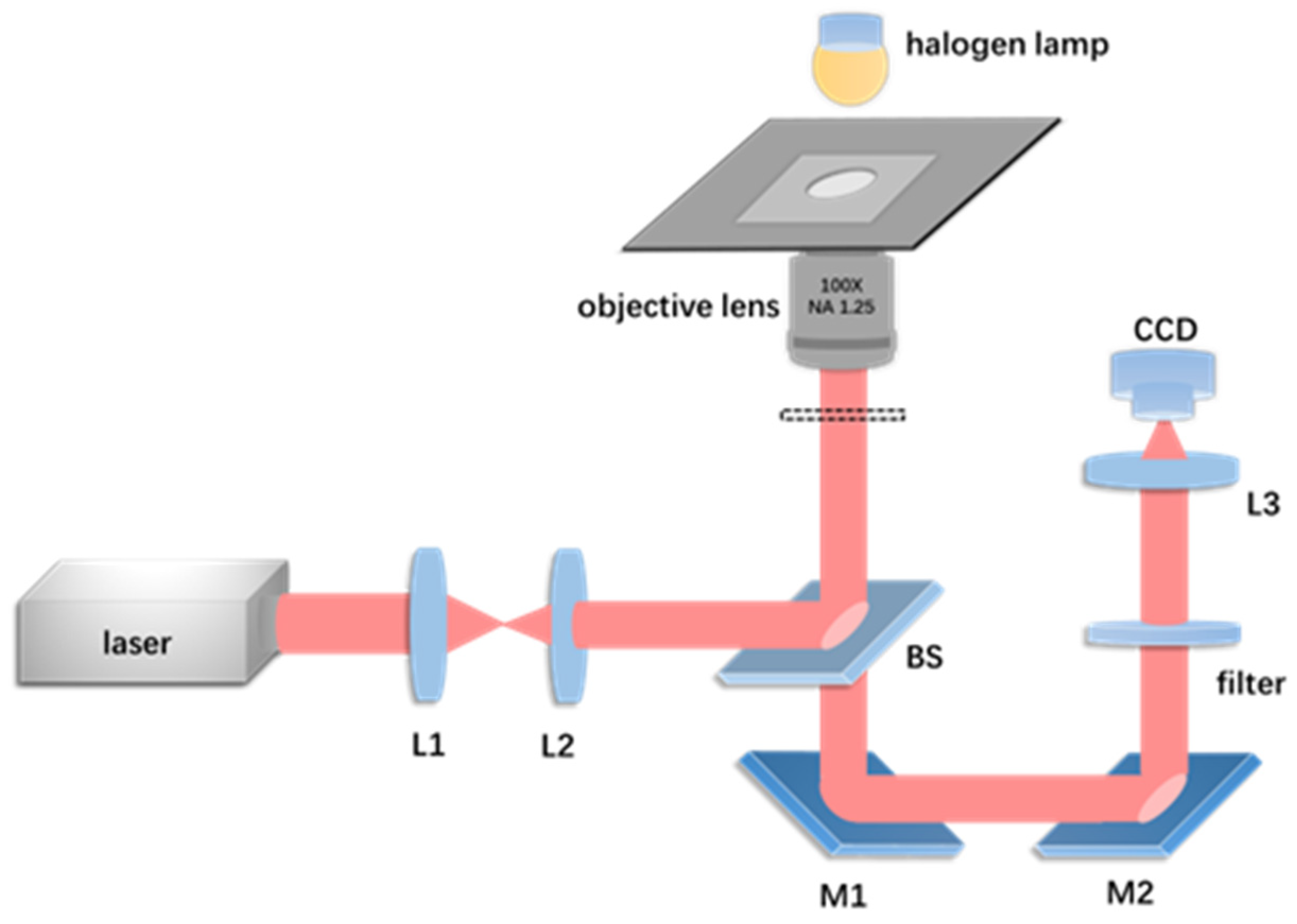
Figure 1. Experimental optical trapping system design. The magnification of the objective lens is 100× and NA is 1.25. L1, L2, and L3 are lenses with focal lengths of 5 cm, 3 cm, and 10 cm, respectively; M1, M2, mirror; BS, beam splitter, the transmission and reflection ratio is approximately 3:2.
Photonics 11 00248 g001
Figure 2. (a) Optical field distribution at 808 nm without PS particles. (b) The light field distribution of 808 nm wavelength trapping of a 10 μm diameter PS particle. The black circle represents a PS particle. (c) Optical force acting on the microsphere along the y-axis. (d) Optical force acting on the microsphere along the x-axis.
Photonics 11 00248 g002
Figure 3. The combined arrangement of single PS particles and the rotation of multiple particles in the two-dimensional plane are controlled by the 808 nm continuous-wave laser. (I) Four particles form a “7” shape in (a), five particles form a “hollow core pentagon” in (b), and six particles form a “solid core pentagon” in (c). (II) Three-particle group rotating clockwise. (III) Two-particle group rotating counterclockwise and shifting. (IV) Three-particle group rotating counterclockwise. (a–c) show the rotation process of a multi-particle group in a two-dimensional plane, respectively. Scale bar, 10 μm.
Photonics 11 00248 g003
Figure 4. The 808 nm laser controls the rotation and displacement of the multi-particle group in three-dimensional space. (I) The process of the “one-shaped” three-particle group moving and rotating near the laser focus (Video S1). (II) The process of manipulating the three-dimensional rotation of the “angular” three-particle group (Video S2). (III) Three-dimensional rotation and movement process of the “cone” four-particle group (Video S3). Scale bar, 10 μm.
Photonics 11 00248 g004
Figure 5. Directional movement of PS particles and fibroblasts manipulated by 808 nm and 1030 nm laser beams. (I) Manipulation of PS particles to move downward and then rightward with 808 nm laser. (II) Manipulation of PS particles to move leftward and then upward with 1030 nm laser. (III) Manipulation of fibroblasts to move rightward and then upward with 808 nm laser (Video S4). (IV) Manipulation of fibroblasts to move downward and then rightward with 1030 nm laser (Video S5). White circles indicate the manipulated targets and arrows indicate the direction of movement. Scale bar, 10 μm.
Photonics 11 00248 g005
Figure 6. Process of bubble generation when the 1030 nm femtosecond laser spot is focused near the surface of the particles. (a) Single PS particle before the laser is turned on. (b) After the laser is turned on, a bubble is rapidly generated on the surface of the particle and expands to the maximum. (c) After the laser is turned off, the bubble gradually shrinks. (d) About 5 s after the laser is turned off, the bubble disappears. (e) Two PS particles before the laser is turned on. (f) After the laser is turned on, a bubble is generated on the surface of one particle. (g) The bubble shrinks and pushes two adhered particles to produce displacement. Scale bar, 10 μm.
Photonics 11 00248 g006
Figure 7. Changes in relative position and orientation of two fibroblasts over time. The blue dotted circle is the reference cell and the green dotted circle is the manipulated cell. The arrows indicate the changes in position and orientation of the manipulated cell relative to the reference cell. (ai) Changes in the position of manipulated fibroblasts relative to reference cells at different times. Scale bar, 10 μm.
Photonics 11 00248 g007
Table 1. The manipulation velocity of PS microparticles and fibroblasts with 808 nm and 1030 nm laser sources at different powers.
808 nm PS808 nm Fibroblasts1030 nm PS1030 nm Fibroblasts
Power
(mW)
Velocity
(μm/s)
Power
(mW)
Velocity
(μm/s)
Power
(mW)
Velocity
(μm/s)
Power
(mW)
Velocity
(μm/s)
15.341.71962.880.8790.962.3444.301.758
18.651.91467.561.2701.162.6375.902.246
21.532.10971.761.4561.182.8327.362.441
24.652.24675.791.5631.363.2238.623.555
27.402.44180.261.7181.593.6139.683.809
32.812.63784.421.8551.783.80910.164.004
36.042.83288.601.9141.994.00410.604.590
41.423.22392.391.9922.194.19911.444.883
44.533.418------
Disclaimer/Publisher’s Note: The statements, opinions and data contained in all publications are solely those of the individual author(s) and contributor(s) and not of MDPI and/or the editor(s). MDPI and/or the editor(s) disclaim responsibility for any injury to people or property resulting from any ideas, methods, instructions or products referred to in the content.