OLED-Pumped Organic Laser Diode


1
Eindhoven Hendrik Casimir Institute, Eindhoven University of Technology, P.O. Box 513, 5600 MB Eindhoven, The Netherlands
2
Laboratoire de Physique des Lasers, Université Sorbonne Paris Nord, UMR CNRS 7538, 99 Avenue JB Clement, 93430 Villetaneuse, France
3
Centrale de Proximité en Nanotechnologies de Paris Nord, Université Sorbonne Paris Nord, 99 Avenue JB Clement, 93430 Villetaneuse, France
*
Author to whom correspondence should be addressed.
Photonics 2024, 11(4), 327; https://doi.org/10.3390/photonics11040327
Submission received: 28 February 2024
/
Revised: 21 March 2024
/
Accepted: 29 March 2024
/
Published: 1 April 2024
(This article belongs to the Special Issue New Perspectives in Semiconductor Optics)
Abstract
:A theoretical analysis is presented for a recently proposed high-speed µ-OLED optically pumped organic laser. We confirm that for this configuration, the laser threshold is reached at a lower current density than in the case of a direct-electrically pumped organic laser diode while generating pulses of order duration. With a validated model for the electrically pumped organic light-emitting diode (OLED), we simulate the generation of light pulses. This light is fed into the organic laser section, where it optically pumps the emitting organic medium. The full model includes field-enhanced Langevin recombination in the OLED, Stoke-shifted reabsorption in both the OLED and organic laser, and an optical cavity in the latter. We numerically demonstrate modulation and conjecture the feasibility of data transmission with this device.
1. Introduction
The successful operation of electrically pumped organic lasers diodes is severely challenged by bimolecular processes in the active region which together with polaron and triplet-induced light absorption lead to gain quenching and higher laser threshold [1]. To some extent, these problems were overcome using the special active material BsB-Cz by Sandanayaka et al. [2], but their demonstration of lasing left room for doubt as to the stability and yield of the device. An excellent introduction into organic lasers can be found in a paper by Samuel and Turnbull [3].
The recent paper by Yoshida et al. [4] demonstrates a new and successful way of separating the electrical injection and the generation of the laser light in one integrated device. In this way, the laser part of the device is optically pumped by the electroluminescence of the electrically pumped part. This has two advantages, namely the laser gain in the organic medium is not quenched by the excessively generated triplets typical of polaron recombination [5] and the laser light suffers less polaron and triplet absorption [1], so that the laser threshold will be easier to achieve. Moreover, by matching the refractive indices of the electroluminescence section and the active laser material section, the pump light can be transferred from the organic light-emitting diode (OLED) to the laser section with high efficiency [4].
In this paper, a dynamical model validated for an electrically pumped OLED [6,7], is extended to include the optical pumping of the organic-laser section. The electroluminescent light generated in the OLED section then excites the organic active molecules in the laser section, leading to the generation of singlet excitons necessary for lasing. The model includes field-enhanced Langevin recombination [8,9] in the OLED section, an optical cavity in the laser section [3] and Stokes-shifted reabsorption [10] in both sections.
The results confirm that in this configuration, the threshold for lasing in terms of the required cavity -factor can be significantly reduced compared to direct electrical pumping. Despite the optical pumping of the active region, triplet excitons are generated due to intersystem crossing (ISC) but at a much slower rate than in the case of direct electrical pumping. The triplet lifetime of will allow the pulsed laser to operate at repetition rate. Moreover, modulations at are numerically demonstrated, which may be favorable for 0.025 megabit optical data transmission. The length of the emitted laser pulses is on the order of but is ultimately limited by the triplet accumulation in the OLED [5]. Therefore, it seems to be very difficult to obtain Continues-Wave (CW) type emission and gigabit data transmission with this kind of device.
2. Model Description
We consider the combined OLED and laser configuration presented in [4] and sketched in Figure 1, where the upper part shows the OLED layer stack and the lower part the organic-laser layers with the coupling layer in between. The laser cavity defined by the substructured grating is indicated. The laser light (indicated green) travels back and forth horizontally. The substructured grating defines the cavity and provides the outcoupling of the light from the bottom. The electroluminescent light (indicated blue) generated in the OLED emitting layer is guided downwards to pump the laser gain medium (indicated green). Detailed information about the structural composition of the integrated structure can be found in [4].
2.1. OLED Model
The set of rate equations for the OLED is for the host-only organic gain material 2,7-Bis (9,9-spirobifluoren-2-yl)-9,9-spirobifluorene (TSBF) proposed in [4], with luminescence wavelength within the absorption spectrum of the laser gain medium. The evolutions of gain and photon generation are described in our current-driven model [7], extended by a model for the electrical circuit adopted from Ahmad et al [11]. In that model, the relation between the applied voltage and the diode injection current is given by
with the voltage over the diode, satisfying
in which and are respectively a series resistance and the resistance of the layer stack and is the capacitance of the layer.
For a given applied voltage , the corresponding injection current given by (1) is input in the set of rate equations that characterize the emission of light from the OLED. denotes the polaron density, () the density of singlet (triplet) excitons, the photon density, the density of host molecules, the density of molecules in the ground state and the ground-state fraction. The model equations then read (the small contributions of singlet-singlet absorption (SSA), triplet-triplet absorption (TTA), and triplet-polaron absorption (TPA), see [8], are neglected)
Conservation of the total number of molecules requires the ground-state density :
In (3), is the thickness and the area of the active layer. In (3)–(5), the quantity is the Langevin recombination rate, given by
where the exponential enhancement is due to the Poole–Frenkel effect in the polaron mobilities [8,9], with the activation voltage [12].
The polarons recombine by Langevin recombination to form excitons, 25% of which are singlet states and 75% triplet states [6]. This is described by the usual rate Equations (3)–(5) for the polarons , singlets and triplets . Equation (6) describes the generation of photons , where it is noted that only the singlets emit light, while in addition to reabsorption by the singlets, the triplets and polarons absorb light as well.
It should be remarked that (3) and (4), strictly speaking, are correct only so long ground-state molecules are abundantly available for the generation of excitons by Langevin recombination, i.e., so long as remains close to unity. This is, in fact, a shortcoming of Equations (4) and (5), since the creation of singlet and triplet excitons has not been subjected to the availability of ground-state molecules. This has been solved in an ad-hoc way in our previous models [7,13] by multiplying the polaron recombination source terms with the ground-state probability. This did guarantee the conservation of total molecules, but erroneously it allows the electrical current to flow even when recombination ceases due to vanishing ground-state probability. A new model solving this issue is under construction [14], but not yet ready for use.
The applied voltage switch-on at and off at is taken gradually and modeled as
with the sigmoid function and the durations of switching. A fraction of the photons generated are coupled into the laser medium. Hence, this light serves as the pump for the organic laser.
All parameters are identified with their values in Table 1. Here, for many parameters, a reference is given to a publication from where this value was taken. For other parameters realistic estimates are given, whereas a few parameter values are chosen because the precise value is either irrelevant (in the sense that the main conclusions do not depend on that choice; some examples are ) or a non-zero value is needed (in the case of ) to prevent the occurrence of unphysical numerical results.
2.2. Laser Model
The model equations for the laser apply to the host-only organic gain material 4,4′-bis[(N-carbazole)styryl]biphenyl (BSB-Cz), with luminescence wavelength and again, the small contributions of SSA and TTA are neglected. In the laser, no polarons are created; instead, singlets are created by the luminescent light from the OLED. The equations in the laser section then read
Here, is the singlet density in the laser active medium. These singlets are created by excitation from the ground state by absorption of photons from the OLED, see (9), where is their fraction that reaches the laser active region. There is no direct generation of triplets in the laser gain region, but there is indirect generation by intersystem crossing (ISC), see (10). The generation of photon density in the laser cavity, , is described in (11), where the first term on the right-hand side is the net stimulated emission, the second term is the cavity loss, and the last term is the spontaneous emission source term. The parameters for the laser section are identified with their values in Table 2.
3. Results
3.1. OLED Performance
Numerical results are obtained by integration of the rate Equations (2)–(6) using (1) and (8) under condition (7) with realistic parameter values as given in Table 1. The voltage is switched on at and turned off at Figure 2 shows the diode voltage (blue), the resulting Langevin recombination rate (green), and the current density (yellow). The overshoot of the current density directly after switch-on is a consequence of the capacitance loading. The evolution of the various variables that characterize the molecular properties of the emitting layer material in the OLED is shown in Figure 3. Here, we see that the photon density (red curve) follows the singlet density (yellow curve), that is, they have similar shapes, which indicates that the emitted light is predominantly spontaneous emission [13].
Note the peculiar behavior of the polarons in Figure 3 with the “ears” at the switch-on and switch-off positions. Here, it should be realized that the model rate equations do not account for the delay and after-effects associated with the finite mobility of charges, which will be most notable for the polarons. Therefore, the overshoot of directly after switch-on and switch-off, should not be taken seriously, although they represent the formal solution of the rate equation. It can be seen by the inspection of the rate equations, that these details have no sizeable influence on the evolutions of and .
Note, also in Figure 3, that the triplet exciton density (green curve) rises to a value of , i.e., 13% of the total molecular density at , or starts deviating from unity noticeably. This means that we are approaching the edge of the applicability of (3) and (4), as stated just below (8) and therefore the applicability of our simulations is to electrical pulses not exceeding a length of .
3.2. Laser Performance
For the same case as in Figure 2, the time evolutions of the variables that characterize the molecular and light-emitting properties of the emitting layer in the laser section are shown in Figure 4. Here, the threshold value is , which is what the singlets should have for lasing, i.e., see (12),
is indicated by the green curve. The linewidth of the emitted light, i.e.,
is given by the purple curve. The clamping of to its threshold value, as well as the substantial drop in linewidth are evidence of lasing taking place.
The strong line narrowing of the emitted laser light when passing the laser threshold is illustrated in Figure 5, for the same parameter setting as in Figure 2. The minimum linewidth drops from at to at . By inspection of Figure 5, the laser threshold is at , which is confirmed by checking that the clamping of the singlets occurs from this value. This value is less than a factor ½ times the threshold if the organic laser had been electrically pumped, due to the substantial quenching of the gain by triplet excitons (see Figure 3). In the latter case, with the same cavity , the lasing threshold would be at . Note that, according to (15), the gradual increase in stimulated emission enhances the effective cavity -factor, which leads to the gradual linewidth decrease on increasing current density.
At the threshold current, the peak photon density generated in the OLED amounts . Taking into account the coupling factor , this corresponds to a threshold optical pump intensity for the organic laser of .
Finally, let us investigate to what extent this laser can be used for ultrafast optical communication. The modulation capability is illustrated by the simulation result shown in Figure 6. In this simulation, we replace the voltage in (9) by
where the modulation index and is the modulation frequency.
The example in Figure 6 is for , and the laser operates at , i.e., 50% above the threshold. It clearly illustrates that modulation in this pulsed-operating OLED-pumped organic laser is a promising feasibility for which experimental verification is most desirable. However, approximately 25 bits of information can be transmitted in one pulse of width. With an exciting pulse frequency of , we could achieve a data rate of . For ultra-fast communication, we really need the laser to operate in (quasi) CW, but for the OLED-pumped organic laser investigated here, this may not be feasible due to triplet accumulation at high electrical current in the OLED after a few tens of nanoseconds.
Table 3 summarizes the main numerical results obtained in this study.
4. Conclusions and Discussion
Electrically pumped organic laser diodes suffer from gain quenching due to the accumulation of triplet excitons, which are abundantly formed in the process of Langevin recombination [8]. This leads to high current-density threshold values. However, optically pumped organic lasers have only minor triplet generation, which led Yoshida et al [4] to successfully pump an organic laser diode with a built-in OLED, so as to separate the electrical part from the organic-laser section.
Inspired by the Yoshida paper [4], we simulated the operation of such an OLED-pumped organic laser on the basis of rate equations for the time evolution of various constituent variables of the gain and photon generations. With the organic gain material TSBF and laser gain material BsB-Cz, we numerically demonstrated pulsed laser emission of to duration per pulse with threshold values on the order of . The parameters were taken from Ou et al [16]. This threshold-current value was derived for a cavity , but can be smaller or larger when is larger or smaller, respectively. In the case of a direct electrically pumped organic laser with the same cavity , we obtained a laser threshold at .
The clamping of the density of light-emitting singlet excitons was numerically demonstrated when passing the threshold of lasing. Together with the line narrowing of the emitted laser light from the cavity-imposed linewidth (a few nm) well below the threshold to well above the threshold, these are features of lasing. The modulation capability of the laser was demonstrated numerically in Figure 6 and leads to the conclusion that optical data transmission may be well feasible.
It is noted that the model rate equations are of the “lumped-cavity” type, where all variables are taken at one particular position in the middle of the cavity and all evolve at the same time. This is a crude approximation of the, in reality, very complicated mixture of processes that occur in the organic layers, with delay and after-effects. However, we believe that the qualitative conclusions and quantitative orders of magnitude are correctly predicted. Future experiments are needed to verify these claims.
Author Contributions
Conceptualization and methodology, D.L. and A.F.; formal analysis and original draft preparation, D.L.; supervision, project administration, review and editing, A.F. All authors have read and agreed to the published version of the manuscript.
Funding
This work is supported by the Netherlands Organization for Scientific Research (NWO): Zwaartekracht Grant “Research Center for Integrated Nanophotonics”; in part by the Agence Nationale de la Recherche (ANR) through the 453 Investissement d’Avenir Programs under Grant ANR-11-IDEX-0005-02; in part by the Labex SEAM: Science Engineering, 454 Advanced Materials; in part by IdEx Université de Paris under Grant ANR-18-IDEX-0001; and in part by ANR funded DEμS CRP Project under Grant ANR-21-CE24-0016-02.
Institutional Review Board Statement
Not applicable.
Informed Consent Statement
Not applicable.
Data Availability Statement
The data presented in this study are available on request from the corresponding author.
Conflicts of Interest
The authors declare no conflicts of interest.
References
- Kasemann, D.; Brückner, R.; Fröb, H.; Leo, K. Organic light-emitting diodes under high currents explored by transient electroluminescence on the nanosecond scale. Phys. Rev. B 2011, 84, 115208. [Google Scholar] [CrossRef]
- Sandanayaka, A.S.D.; Matsushima, T.; Bencheikh, F.; Terakawa, S.; Potscavage, W.J.P., Jr.; Qin, C.; Fujihara, T.; Goushi, K.; Ribierre, J.-C.; Adachi, C. Indication of current-injection lasing from an organic semiconductor. Appl. Phys. Express 2019, 12, 061010. [Google Scholar] [CrossRef]
- Samuel, I.D.W.; Turnbull, G.A. Organic semiconductor lasers. Chem. Rev. 2007, 107, 1272–1295. [Google Scholar] [CrossRef] [PubMed]
- Yoshida, K.; Gong, J.; Kanibolotsky, A.L.; Skabara, P.J.; Turnbull, G.A.; Samuel, I.D. Electrically driven organic laser using integrated OLED pumping. Nature 2023, 621, 746–752. [Google Scholar] [CrossRef] [PubMed]
- Giebink, N.C.; Forrest, S.R. Temporal response of optically pumped organic semiconductor lasers and its implication for reaching threshold under electrical excitation. Phys. Rev. B 2009, 79, 073302. [Google Scholar] [CrossRef]
- Ouirimi, A.; Chime, A.C.; Loganathan, N.; Chakaroun, M.; Fischer, A.P.; Lenstra, D. Threshold estimation of an organic laser diode using a rate-equation model validated experimentally with a microcavity OLED submitted to nanosecond electrical pulses. Org. Electron. 2021, 97, 106190. [Google Scholar] [CrossRef]
- Lenstra, D.; Fischer, A.P.; Ouirimi, A.; Chime, A.C.; Loganathan, N.; Chakaroun, M. Organic Diode Laser Dynamics: Rate-Equation Model, Reabsorption, Validation and Threshold Predictions. Photonics 2021, 8, 279. [Google Scholar] [CrossRef]
- Gärtner, C. Organic Laser Diodes: Modelling and Simulation. Ph.D. Thesis, Universität Karlsruhe, Karlsruhe, Germany, 2008. [Google Scholar]
- Murgatroyd, P.N. Theory of space-charge-limited current enhanced by Frenkel effect. J. Phys. D Appl. Phys. 1970, 3, 151. [Google Scholar] [CrossRef]
- Gispert, J.R. Coordination Chemistry; Wiley-VCH: Hoboken, NJ, USA, 2008; p. 483. ISBN 3-527-31802-X. [Google Scholar] [CrossRef]
- Ahmad, V.; Sobus, J.; Greenberg, M.; Shukla, A.; Philippa, B.; Pivrikas, A.; Vamvounis, G.; White, R.; Lo, S.-C.; Namdas, E.B. Charge and exciton dynamics of OLEDs under high voltage nanosecond pulse: Towards injection lasing. Nat. Commun. 2020, 11, 4310. [Google Scholar] [CrossRef] [PubMed]
- Kao, K.C. Dielectric Phenomena in Solids; Elsevier Academic Press: San Diego, CA, USA, 2004; ISBN 9780123965615. [Google Scholar]
- Lenstra, D.; A Fischer, A.P.; Ouirimi, A.; Chime, A.C.; Loganathan, N.; Chakaroun, M. Ultra-short optical pulse generation in micro OLEDs and the perspective of lasing. J. Opt. 2022, 24, 034007. [Google Scholar] [CrossRef]
- Lenstra, D.; Fischer, A.; Ouirimi, A.; Loganathan, N.; Chakaroun, M. OLED-pumped Organic Laser. Proc. SPIE Photonics Eur. 2024; submitted. [Google Scholar]
- Gartner, C.; Karnutsch, C.; Pflumm, C.; Lemmer, U. Numerical Device Simulation of Double-Heterostructure Organic Laser Diodes Including Current-Induced Absorption Processes. IEEE J. Quantum Electron. 2007, 43, 1006–1017. [Google Scholar] [CrossRef]
- Ou, Q.; Peng, Q.; Shuai, Z. Computational screen-out strategy for electrically pumped organic laser materials. Nat. Commun. 2020, 11, 4485. [Google Scholar] [CrossRef] [PubMed]
Figure 1.
Schematic of the OLED-pumped organic laser.

Figure 2.
Time evolutions of diode voltage, current density, and Langevin recombination. The voltage (50 V) is switched on at and switched off at . The plateau value of the electrical current is 3.84 kA/cm2, which is reached at after switch-on.
Figure 2.
Time evolutions of diode voltage, current density, and Langevin recombination. The voltage (50 V) is switched on at and switched off at . The plateau value of the electrical current is 3.84 kA/cm2, which is reached at after switch-on.
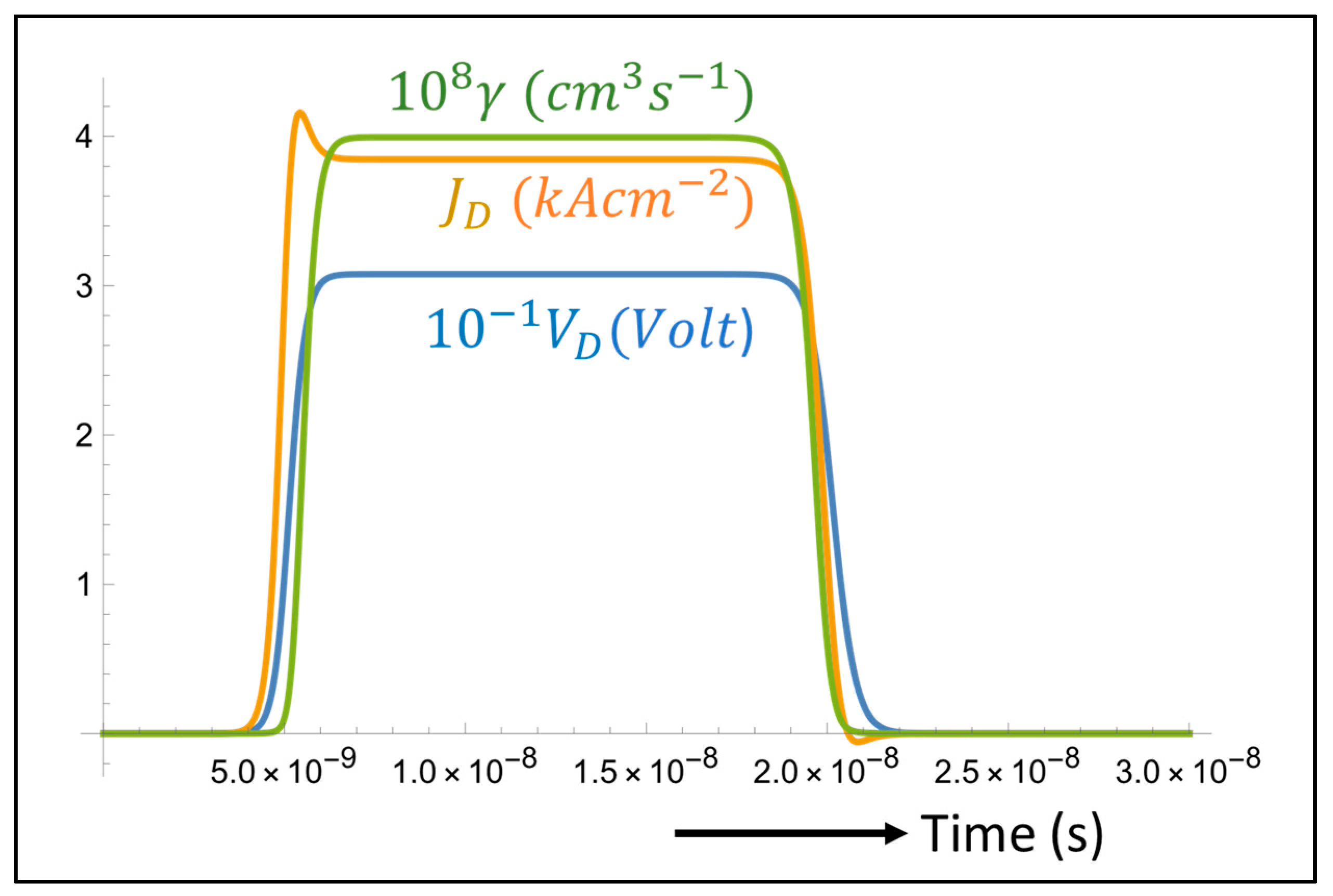
Figure 3.
Time evolutions of the molecular densities in the OLED for the case of Figure 2. The photon density is represented by the red curve. This light serves as the pump for the organic laser.
Figure 3.
Time evolutions of the molecular densities in the OLED for the case of Figure 2. The photon density is represented by the red curve. This light serves as the pump for the organic laser.
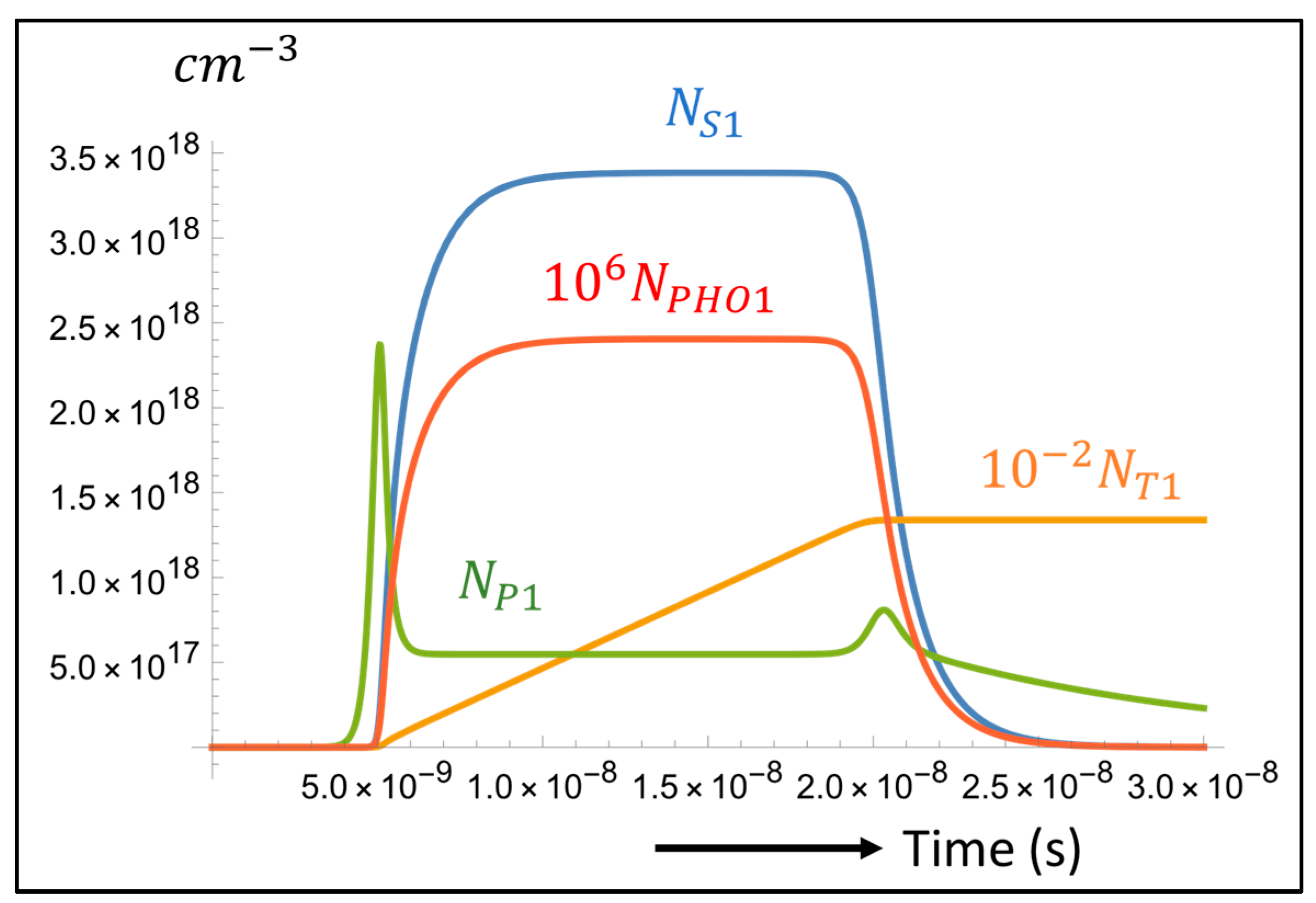
Figure 4.
Time evolution of variables for the setting of Figure 2. The singlet density (blue curve) is clamped to the threshold value (green curve) from to , during which period laser light is emitted (, red curve), while the linewidth of the laser light (purple curve) drops from to .
Figure 4.
Time evolution of variables for the setting of Figure 2. The singlet density (blue curve) is clamped to the threshold value (green curve) from to , during which period laser light is emitted (, red curve), while the linewidth of the laser light (purple curve) drops from to .

Figure 5.
Time-integrated photon density (blue) and minimum linewidth (yellow) versus current density. The laser threshold is around .. The minimum linewidth at is .
Figure 5.
Time-integrated photon density (blue) and minimum linewidth (yellow) versus current density. The laser threshold is around .. The minimum linewidth at is .

Figure 6.
Laser photon density with modulation. The applied voltage was modulated with modulation index around .
Figure 6.
Laser photon density with modulation. The applied voltage was modulated with modulation index around .


Table 1.
Model parameters (OLED, TSBF).
| Symbol | Name | Value | Ref. |
|---|---|---|---|
| OLED series resistance | Choice | ||
| OLED layer resistance | Choice | ||
| OLED diode capacitance | Estimate | ||
| d | OLED active layer thickness | 20 nm | [4] |
| OLED active area | Choice | ||
| elementary charge | - | ||
| Molecular density (TSBF) | 1.0 × 1021 cm−3 | Estimate | |
| Zero-field Langevin recombination rate | 6.2 ×10⁻¹² cm3 s−1 | [15] | |
| Polaron decay rate | Choice | ||
| Singlet-exciton decay rate | 7.7 × 10⁸ s−1 | [16] | |
| Singlet-exciton radiative decay rate | 7.1 × 10⁸ s−1 | [16] | |
| Triplet decay rate | 1 × 10³ s−1 | [16] | |
| Inter-system crossing rate | 2.7 × 10⁵ s−1 | [16] | |
| Singlet-polaron annihilation (SPA) rate | 1 × 10⁻¹⁰ s−1 | [8] | |
| Γ | Confinement factor | 0.29 | [6,13] |
| Stimulated emission gain coefficient | 5.7 × 10⁻⁶ cm3 s−1 | [16] | |
| Reabsorption coefficient | 1.5 × 10⁻⁸ cm3 s−1 | [16] | |
| Triplet absorption (TA) coefficient | 3.5 × 10⁻⁸ cm3 s−1 | [16] | |
| Polaron absorption (PA) coefficient | 1.15 × 10⁻⁶ cm3 s−1 | [16] | |
| Spontaneous emission factor | 0.504 | Estimate | |
| Activation voltage (Poole-Frenkel) | 0.4 Volt | [13] | |
| Peak luminescence wavelength | 440 nm | [4] | |
| Peak absorption wavelength | 370 nm | [16] | |
| Duration of current switch-on | 0.2 ns | Choice | |
| Duration of current switch-off | 0.3 ns | Choice |
Table 2.
Model parameters (Laser; BsB-Cz).
| Symbol | Name | Value | Ref. |
|---|---|---|---|
| Molecular density (BsB-Cz) | 1.0 × 1021 cm−3 | Estimate | |
| Photon transmission OLEDlaser | 0.75 | [4] | |
| Singlet-exciton decay rate | 8.0 × 10⁸ s−1 | [16] | |
| Triplet decay rate | 9.1 × 10³ s−1 | [16] | |
| Inter-system crossing rate | 6.6 × 10⁴ s−1 | [16] | |
| Stimulated emission gain coefficient | 9.4 × 10⁻⁶ cm3 s−1 | [16] | |
| Reabsorption coefficient | 4.4 × 10⁻⁷ cm3 s−1 | [16] | |
| Peak absorption coefficient | 5.3 × 10⁻⁶ cm3 s−1 | [16] | |
| Triplet absorption (TA) coefficient | 3.3 × 10⁻⁷ cm3 s−1 | [16] | |
| Cavity photon decay rate | - | ||
| Spontaneous emission factor | Estimate | ||
| Peak luminescence wavelength | 505 nm | [16] | |
| Peak absorption wavelength | 440 nm | [16] | |
| Cavity refractive index | 1.7 | Estimate | |
| Vacuum light velocity | - | ||
| Cavity quality factor | 500 | Estimate |
Table 3.
Main numerical conditions and results.
| Exciting pulse duration | |
| Excitation pulse repetition rate | |
| Laser threshold current | |
| Laser pulse duration | |
| Laser linewidth | |
| Threshold optical pump intensity | |
| Optical data transmission speed |
Disclaimer/Publisher’s Note: The statements, opinions and data contained in all publications are solely those of the individual author(s) and contributor(s) and not of MDPI and/or the editor(s). MDPI and/or the editor(s) disclaim responsibility for any injury to people or property resulting from any ideas, methods, instructions or products referred to in the content. |
© 2024 by the authors. Licensee MDPI, Basel, Switzerland. This article is an open access article distributed under the terms and conditions of the Creative Commons Attribution (CC BY) license (https://creativecommons.org/licenses/by/4.0/).
Share and Cite
MDPI and ACS Style
Lenstra, D.; Fischer, A. OLED-Pumped Organic Laser Diode. Photonics 2024, 11, 327. https://doi.org/10.3390/photonics11040327
AMA Style
Lenstra D, Fischer A. OLED-Pumped Organic Laser Diode. Photonics. 2024; 11(4):327. https://doi.org/10.3390/photonics11040327
Chicago/Turabian StyleLenstra, Daan, and Alexis Fischer. 2024. "OLED-Pumped Organic Laser Diode" Photonics 11, no. 4: 327. https://doi.org/10.3390/photonics11040327
Note that from the first issue of 2016, this journal uses article numbers instead of page numbers. See further details here.