Abstract
Adaptive free-space optical (FSO) communication links have been extensively studied in order to adapt to variable atmospheric channel environments due to factors such as atmospheric turbulence. As a supporting technology, an all-in-one BPSK/QPSK switchable transmission and reception method is proposed and experimentally demonstrated for adaptive modulation format switching in FSO links. The transmission and reception of both modulation formats are realized based on the same IQ modulator and single-photodetector coherent receiver. Simulation and experimental results show that the QPSK signal has a power penalty of about 3–4 dB compared to the BPSK signal with a BER of about 1 × 10⁻³. The basis for format switching is given according to the various atmospheric channel conditions. The proposed method provides a flexible and efficient solution for variable FSO communication environments to improve their performance.
1. Introduction
Free Space Optical (FSO) communications have attracted considerable attention due to their advantages of high capacity, exceptional confidentiality, fast transmission rates, and long-distance capabilities [1]. FSO communications have been regarded as an attractive alternative technology in many applications, especially in inter-satellite and deep space applications [2]. However, FSO communications are greatly affected by the absorption, scattering, and turbulence effects in the atmospheric channel [3,4]. For example, atmospheric turbulence will cause wavefront distortion, atmospheric scintillation, and beam wander of the optical carrier, leading to serious degradation of signal quality and deterioration of link performance. Reducing the impact of atmospheric turbulence on the FSO transmission has been well studied. In particular, all of these atmospheric effects change in real time, which makes the FSO transmission more challenging.
Several methods have been proposed against atmospheric effects, including coherent reception techniques [5], large-aperture reception [6], diversity reception [7], time-domain processing and threshold optimization [8], coherent modulation techniques [9], and adaptive transmission techniques [10]. Using coherent modulation formats, the system sensitivity can be effectively improved. Moreover, adaptive transmission technology has been demonstrated to be an effective way of adjusting transmission parameters according to real-time channel fading [11]. In recent years, many types of adaptive transmission techniques have been conducted, mostly focusing on power, symbol transmission rate, coding efficiency, modulation format, or a combination of these parameters. These parameters have been proposed for tuning to improve the performance of the FSO link in variable atmospherics [12]. For example, the adaptive format switching between OOK and PPM has been performed by determining the threshold region pattern based on the signal-to-noise ratio (SNR) and turbulence intensity selection [13]. The data rate, modulation scheme, and coding rate for intensity modulation/direct detection (IM/DD) systems have also been proposed for changing under different turbulences [14].
In recent years, it has been demonstrated that phase modulation/coherent detection modulation formats, such as binary phase-shift keying (BPSK) and quadrature phase-shift keying (QPSK), are more competitive than the IM/DD formats including on-off keying (OOK) and pulse position modulation (PPM), etc. [15]. Moreover, the spectral efficiency can be improved by using multi-level phase modulation formats. These multi-level coherent modulation formats are capable of carrying multiple bits of information on each symbol, resulting in improvements in the system’s capacity. However, they require higher optical transmitted power to ensure the same bit error rate (BER) [16]. To adapt to the changing channel environment, it is necessary to switch the modulation formats to transmit as much information as possible without compromising the quality of communication. For example, the transmitter enables the QPSK/16QAM modulation format switching by changing the electrical signals on the IQ modulator between OOK and PAM4 [17]. The switching between OOK and BPSK has been proposed by dynamically controlling the bias point of the Mach-Zehnder modulator (MZM) [18]. The bias voltage algorithm of the IQ modulator has been used to switch OOK, BPSK, and QPSK [19]. The switching between five modulation formats including OOK, BPSK, DPSK, QPSK, and DQPSK has been realized by changing the bias voltage of a certain arm and changing the working mode of MZM [20]. Selecting appropriate modulation formats from BPSK, QPSK, and 8-PSK has been suggested based on the estimated SNR [21]. BER is used as a spectrum maximization metric to adapt MPSK modulations in an FSO link [22].
To support such format switchable functions, a transmitter and a receiver that can deal with multiple kinds of modulation formats simultaneously are urgently demanded. The contributions above mainly focus on compatibility in achieving more modulation formats, and how to transmit all these formats in an all-in-one transmission and reception system has not been well researched. Since phase modulation formats have shown better anti-turbulence performance than intensity modulation formats in FSO links, we mainly focus on phase modulation format switching.
In this paper, we propose and experimentally demonstrate an all-in-one BPSK/QPSK switchable transmission and reception method for real-time variable FSO links to achieve stable communications. In Section 2, principles of the switchable modulation format generation, transmission in atmospheric channels, and link performance evaluation are introduced. In Section 3, the all-in-one BPSK/QPSK switchable transmission and reception system is set up based on an IQ modulator and a single-photodetector (SPD) coherent receiver, which is considered as a competitive coherent receiving technology, as only a photodetector and an analog-to-digital converter are required [23]. The structure is efficiently simplified by processing the two kinds of modulation formats using the same series of devices. In Section 4, switching between 5 Gbit/s BPSK and 10 Gbit/s QPSK signals is demonstrated under moderate turbulence. The transmission performance is measured for both BPSK and QPSK by using a rotating phase plate to simulate the atmospheric environment. BER and constellation diagrams are also simulated based on the phase screen method for the BPSK and QPSK signals. The experimental results agree well with the simulation results. In Section 5, the transmission performance is analyzed for the two kinds of modulation formats under different atmospheric turbulences. The power penalty of the QPSK signal is about 3–4 dB compared to the BPSK signal at a BER of 1 × 10⁻³. The basic criterion for BPSK/QPSK switching is obtained. In Section 6, a conclusion is provided.
2. Operation Principles
2.1. Switchable BPSK/QPSK Generation
The transmitter encodes the data and modulates the electrical signal onto an optical carrier. The optical carrier is often served by a continuous-wave laser, whose field is expressed as and power is . The MZM is based on the interference of light and the output optical power of MZM is [24]:
where and are the phase shifts of the upper and lower arms of MZM, respectively, which can be further expressed as:
where and denote the external voltage of the two arms, and and denote the half-wave voltage. Usually, the MZMs operate in push-pull mode, with the voltage applied to the upper and lower arms equal in magnitude but opposite in direction as in . Then, Equation (1) can be rewritten as:
An IQ modulator often contains two MZMs, which are called I-path and Q-path, operating in push-pull mode and a phase shifter is used. Therefore, Q-path has one more phase shift of π/2 than I-path, and the output QPSK signal synthesized by the two paths is:
where and are the phase shift of the two MZMs respectively. Generally, , and . However, if they are set as , and , the BPSK format will be generated, which can be regarded as a special case of the QPSK format.
2.2. Atmospheric Channel Model
Since atmospheric turbulence is an irregular random movement, it is difficult to determine the specific atmospheric refractive index value at a certain point and a certain time. The Kolmogorov turbulence model provides the wind speed structure function and refractive index power spectral density, which has been proven to be consistent with a number of experimental conclusions [25].
For long-distance FSO communication systems, the signal light can be approximated as a plane wave. Due to the fluctuation of the refractive index, the phase of the received light will fluctuate after transmitting a distance of L. The phase power spectral density can be expressed as [26]:
where denotes the spatial frequency, denotes the outer scale of turbulence, denotes the inner scale of turbulence, and denotes the atmospheric coherent length, which can be expressed as:
where denotes the wave number, is the refractive index construction constant, is Rytov variance, and is the link distance. When the change in phase caused by atmospheric turbulence is small, the phase change along the transmission path can be equivalent to a phase screen [27]. Equation (6) shows a statistical average of the power spectral density. For atmospheric turbulence at a certain moment, the two-dimensional power spectrum of its phase fluctuations is a sample value in the random process, and the mean square value of the random process is . A series of phase screens of atmospheric turbulence can be obtained by power spectral inversion with Fourier transform as in [28]:
where , and is a two-dimensional complex random matrix series that obeys normal distribution in the frequency domain. The role of the -th phase screens can be expressed as:
where is the light field after passing through the phase screen, is the -th phase modulation due to the phase screen, and is the light field incident on the phase screen. For this transmission model, the before the first phase screen is the output of transmitter as in Equation (5), so the role of the first phase screens can be expressed as:
If the whole transmission path is divided into segments with phase screens, there will be:
2.3. Link Performance Evaluation
In an FSO link using phase modulation, the SNR can be expressed as:
where is the variance of the channel noise current, is the received optical power, and represents the responsivity of the receiver. Because of the atmospheric turbulence, the received power on each micro-element area of the receiving plane fluctuates. Taking the example that the whole transmission path is divided into segments with phase screens, the received power on the receiving plane can be expressed as:
where denotes the link loss due to the atmospheric attenuation. For the first phase screen, is uniformly distributed in the plane, so the relationship between it and the transmitted power can be expressed approximately as:
where is the transmitted optical power, and is the area of the transmitted plane. Generally, bit error rate (BER) is often used to measure the performance of communication systems. The average BER of the BPSK and QPSK signals can be expressed as in Equations (16) and (17), respectively [29]:
where is bit energy, is noise power spectral density, and the ratio is a normalized version of SNR. So, the average BER of the BPSK signal and QPSK signal can be further written as:
where is symbol period and is sampling period.
In simulation, the BER can also be obtained as:
When a signal light with a certain SNR transmits through a small area of the phase screen, the signal light will be affected by the atmospheric turbulence in this area, as shown in Equation (11). After demodulating and being compared with the transmission data, the BER of the signal light transmitting in this area of the phase screen can be obtained. The same method can be used to obtain the BERs of the signal lights at different positions on the phase screen. The average BER on the phase screen can be on behalf of the BERs of the signal lights transmitting through the whole phase screen. Similarly, for the signal light transmitted through multiple phase screens as in Equation (12), the BER can also be calculated.
With Equation (15) and iteration over by Equation (12), the relationship between the BER and the transmitted power can be finally obtained. Thus, under given atmospheric turbulence conditions, the BERs of the BPSK and QPSK modulation formats vary with the transmitted power , respectively.
3. Experimental Setup
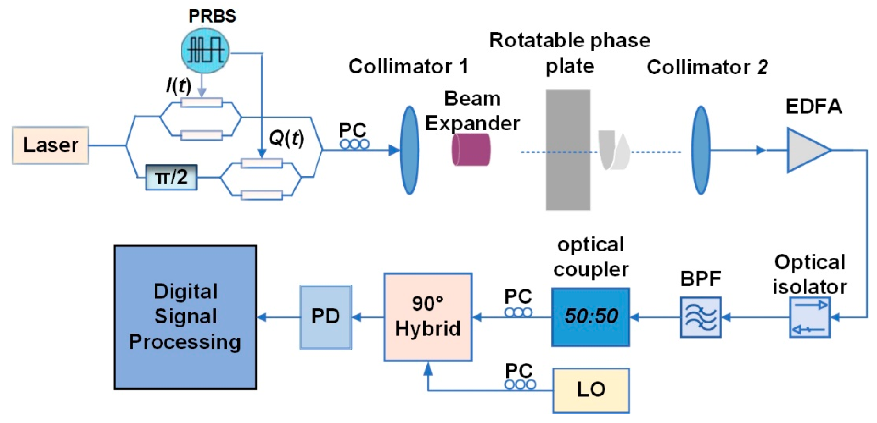
Figure 1 shows the experimental setup of the BPSK/QPSK switchable transmission and reception in a FSO link. A laser source with a wavelength of 1550 nm is used as the optical carrier, which enters an IQ modulator (FTM7961EX, Fujitsu, Kawasaki, Japan). A 10 Gb/s QPSK signal is generated by uploading two pseudo-random binary sequences (PRBS, I(t) and Q(t)) generated by the error analyzer (N10000A, Keysight, Beijing, China) with lengths of 215 − 1 and a rate of 5 Gb/s on the modulator. Moreover, if the electrical signal on one of the two paths is turned off, a 5 Gb/s BPSK signal will be generated. Therefore, the BPSK/QPSK format switching can be realized in this way.
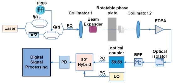
Figure 1.
Experimental setup of FSO transmission and reception with BPSK/QPSK switching. PRBS: pseudorandom binary sequence, PC: Polarization Controller, EDFA: Erbium-doped fiber amplifier, BPF: Bandpass filter, LO: Local Oscillator, PD: photodetector.
Table 1 shows the equipment and system related parameters in the experiment. The modulated optical signal is injected into a collimator (Collimator 1, F280FC-1550, Thorlabs, Newton, NJ, USA) and expanded through an 8× beam expander. It is sent into a simulated atmospheric channel, which is served by a rotating phase plate. After FSO transmission, the optical signal is collected by another collimator (Collimator 2, F280FC-1550, Thorlabs, Newton, NJ, USA) and coupled into an optical fiber. It is amplified by an EDFA and filtered by a band-pass filter with a bandwidth of 0.8 nm, and then mixed with the local oscillator into a 50:50 power coupler for frequency mixing. An SPD coherent receiver is used to convert the optical signal into an electrical signal, which is then acquired by a real-time oscilloscope (DSOZ594A, Keysight, Beijing, China) at a sampling rate of 20 GS/s. The captured data are then transmitted to a computer and handled by off-lined digital signal process (DSP) algorithms.

Table 1.
Equipment and system parameters.
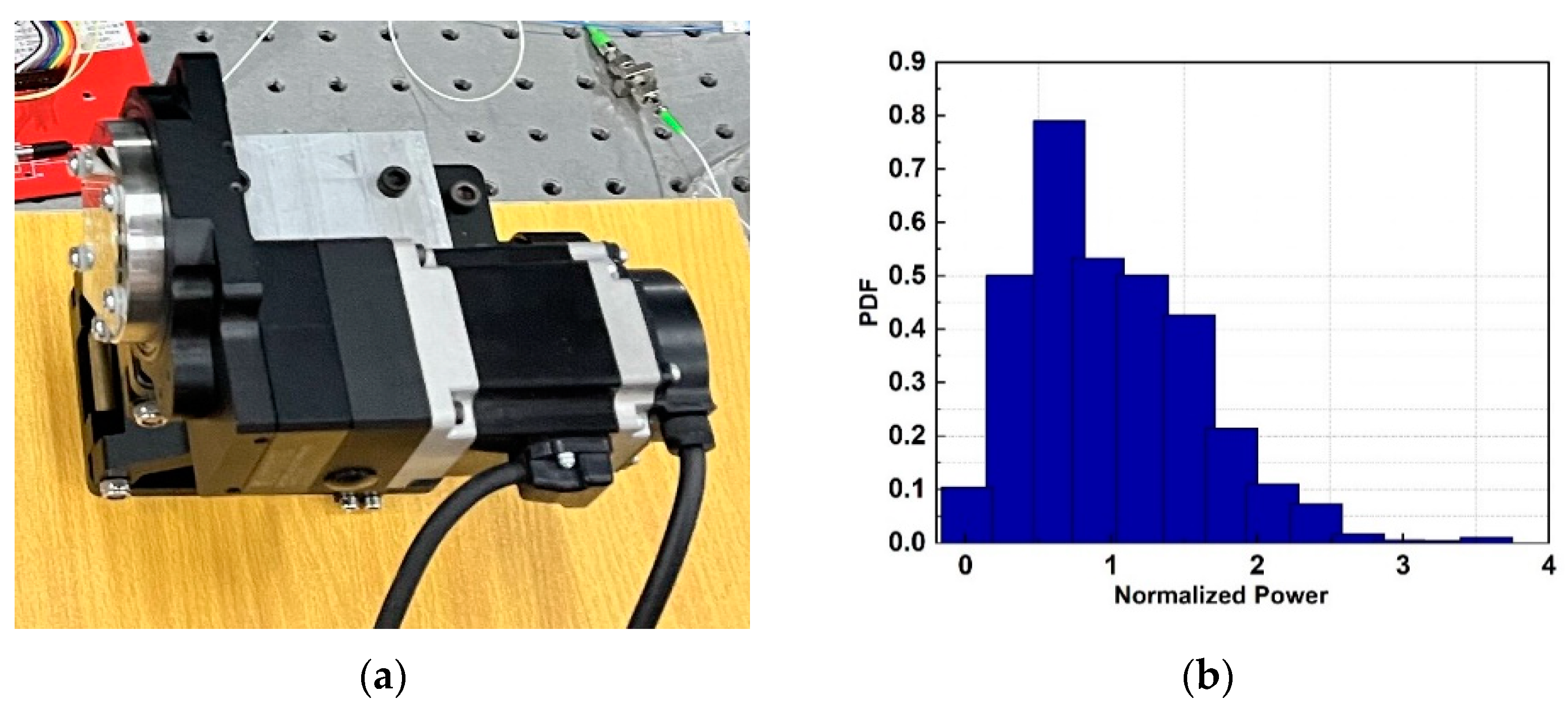
In this experiment, the rotating phase plate, as shown in Figure 2a, is used to simulate the atmospheric turbulence. Figure 2b shows the measured probability density function (PDF) of the normalized received power, where a total of 1200 data points are collected at a sampling interval of 0.1 s. Rytov variance is often used to characterize the intensity of atmospheric turbulence and the degree of refractive index fluctuation [30]. The turbulence level can be classified according to the Rytov variance: is considered as weak turbulence, is considered as moderate turbulence, and is considered as strong turbulence. In our experiment, the equivalent Rytov variance of the rotating phase plate is calculated as 0.4665, and can be considered as moderate turbulence.
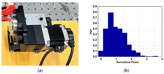
Figure 2.
(a) Photo of the rotating phase plate; (b) measured probability density function (PDF) of the normalized received power.
4. Experimental and Simulation Results
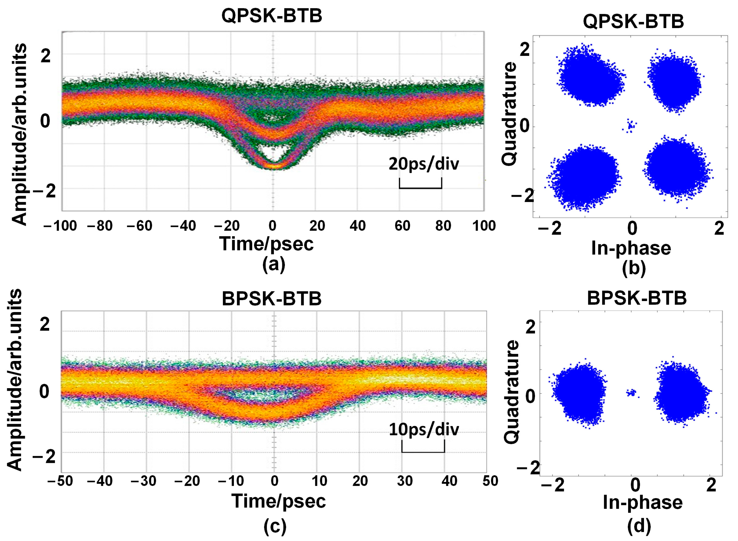
As shown in Figure 3, the back-to-back (BTB) eye diagrams of the generated optical signals are measured using an optical sampling oscilloscope (86100D, Agilent, Santa Clara, USA), where the signal power is fixed at 3.0 dBm. The eye diagrams of the QPSK (Figure 3a) and BPSK (Figure 3c) signals are clearly observed by tuning the modulated data on the IQ modulator. Their constellation diagrams are shown in Figure 3b,d, where the error vector magnitude (EVM) values are calculated to be 0.4329 and 0.4056, respectively. It is feasible to realize the switching between BPSK and QPSK using the proposed method.
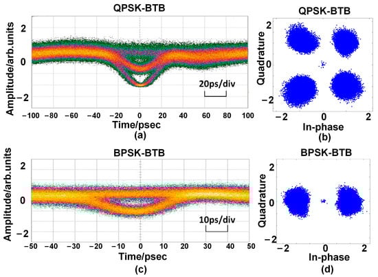
Figure 3.
Measured eye diagrams and BTB constellation diagrams of the generated QPSK and BPSK signals. (a,c) Measured eye diagrams of generated QPSK and BPSK; (b,d) BTB constellation diagrams of the generated QPSK and BPSK.
The loss of the FSO link is evaluated in this experiment. When the transmitted optical power after the IQ modulator is 3 dBm, a receiving power of −39.70 dBm is measured. The link loss is evaluated to be 42.70 dB. This loss seems to be heavy, and the reason mainly lies in the fact that the beam is greatly expanded by an 8x beam expander to simulate the beam spreading over a long-distance FSO link and only a small part of the light is collected by the receiver. Moreover, the amplitude and phase are affected by the inserted rotating phase plate, which will reduce the coupling efficiency between free space and the optical fiber.
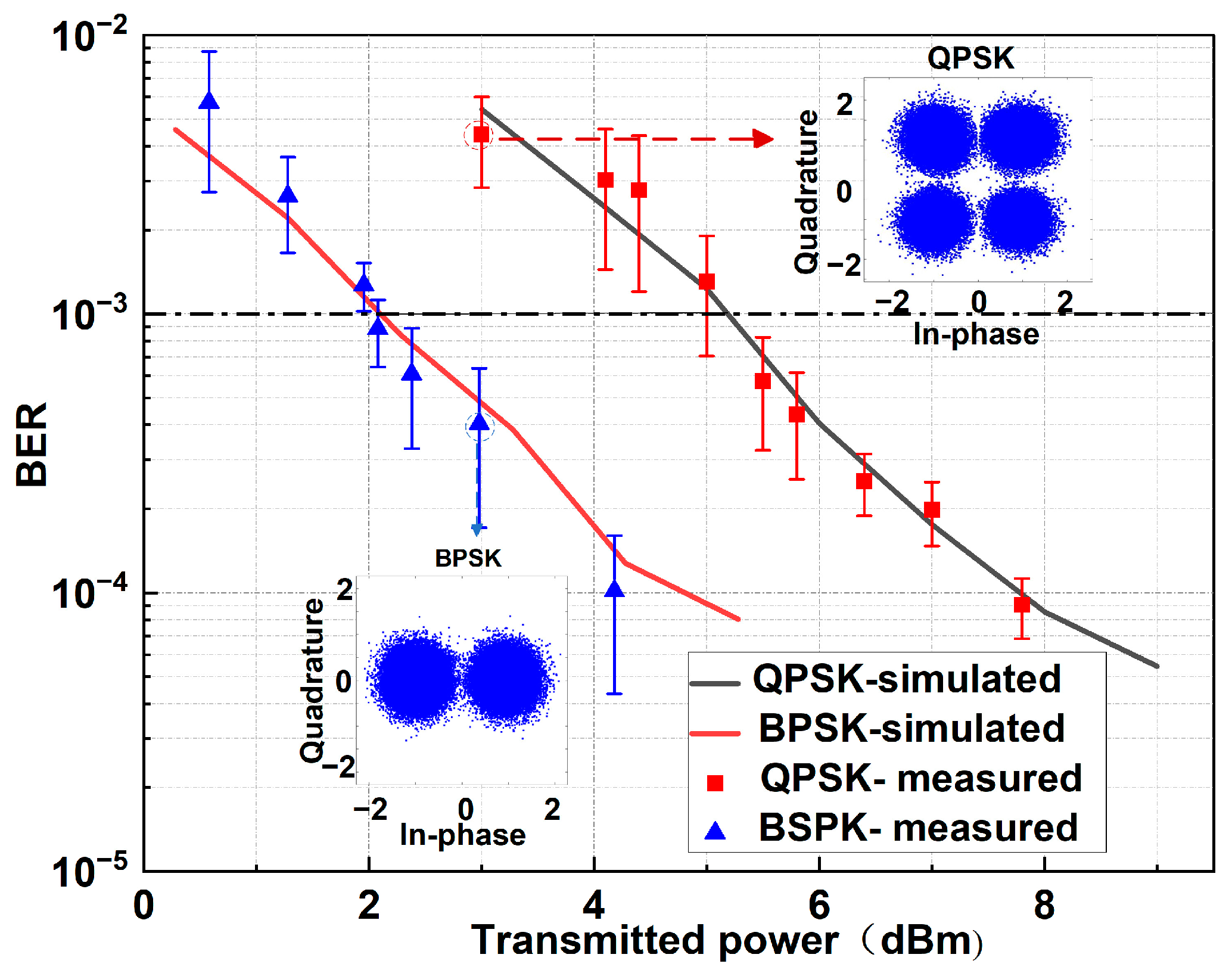
Figure 4 shows the measured BER curves for the BPSK and QPSK signals. In the experiment, the transmitted optical power is adjusted using a variable optical attenuator (VOA), and the wavelength of the local oscillator light is set to be 1550.15 nm. The insets show the constellation diagrams of the received BPSK and QPSK signals. Compared to the BTB case, it can be seen that the constellation diagrams degrade a little. When the transmitted power is 3 dBm, the EVMs of the BPSK and QPSK signals are 0.5358 and 0.6239, respectively. They are larger than the BTB values, which indicates the distortion in the FSO transmission. If a BER of 1.0 × 10⁻³ is considered, the required transmitted powers of the BPSK and QPSK signals are fitted to be 2.05 dBm and 5.12 dBm according to the measured data. Compared to the BPSK signal, the power penalty is obtained as 3 dB. This means that the BPSK signal has better turbulence flexibility than the QPSK signal.
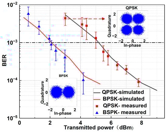
Figure 4.
Measured and simulated BER results of the QPSK and BPSK signals and measured constellation diagrams of the QPSK and BPSK signals.
The transmission performance in the atmospheric channel can be simulated using the phase screen model. According to the experimental conditions, the simulation parameters are set as follows: the incident light carrier is a Gaussian beam with a wavelength of 1550 nm, the radius of the beam waist is 5.0 mm, and the Rytov variance is 0.4665. The transmission distance is divided into 10 segments and a phase screen is set in each segment. Then, 100 sets of data (each containing 1 × 10⁶ symbols) are recorded and the BER is calculated, as shown in Figure 4. The simulation results agree well with the experimental results. At the BER of 1 × 10⁻³, the simulated light powers are 2.12 dBm and 5.19 dBm for the BPSK and QPSK signals, respectively. The differences between the simulation and experimental results are within 0.07 dB.
5. Determination of the Switching Basis
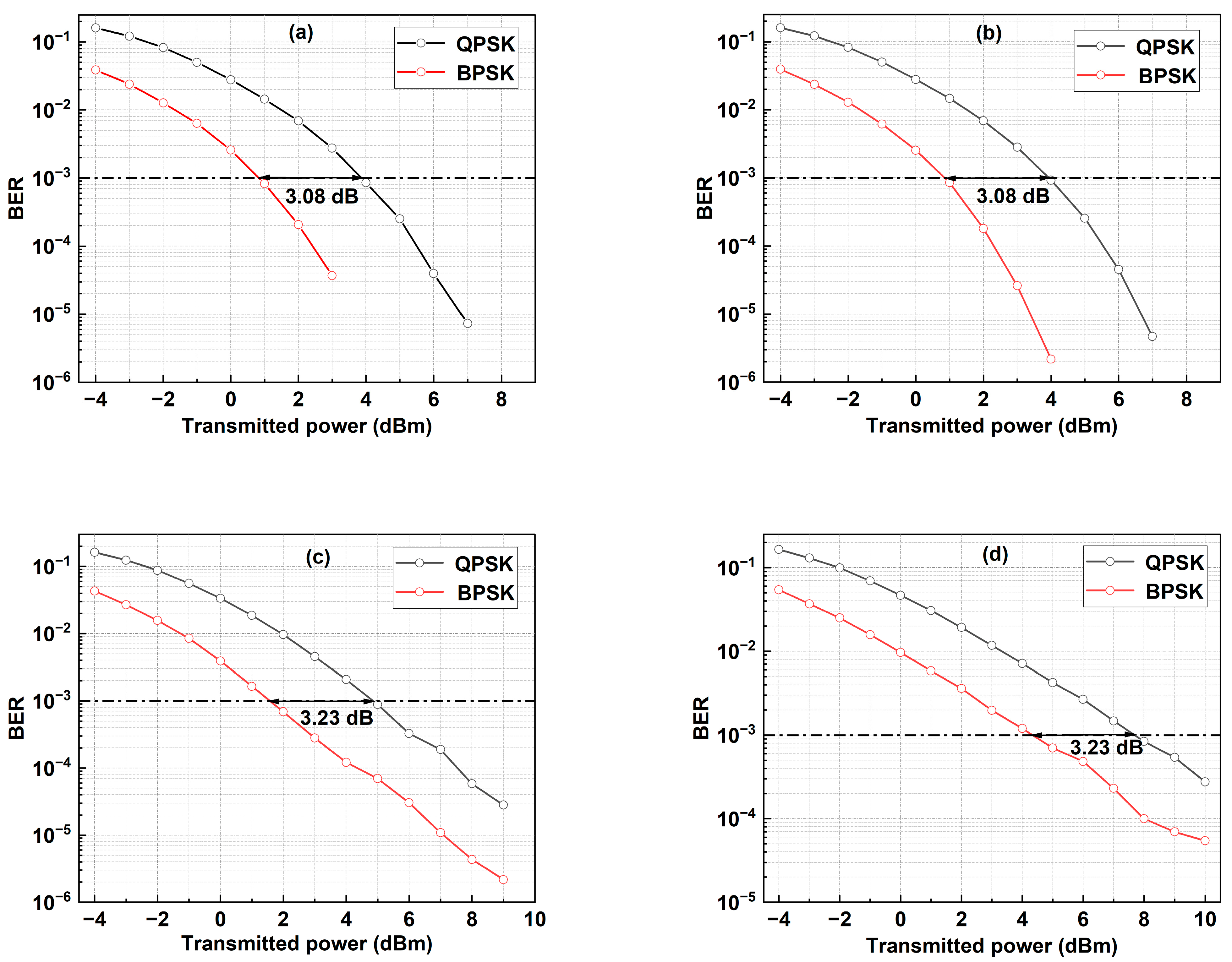
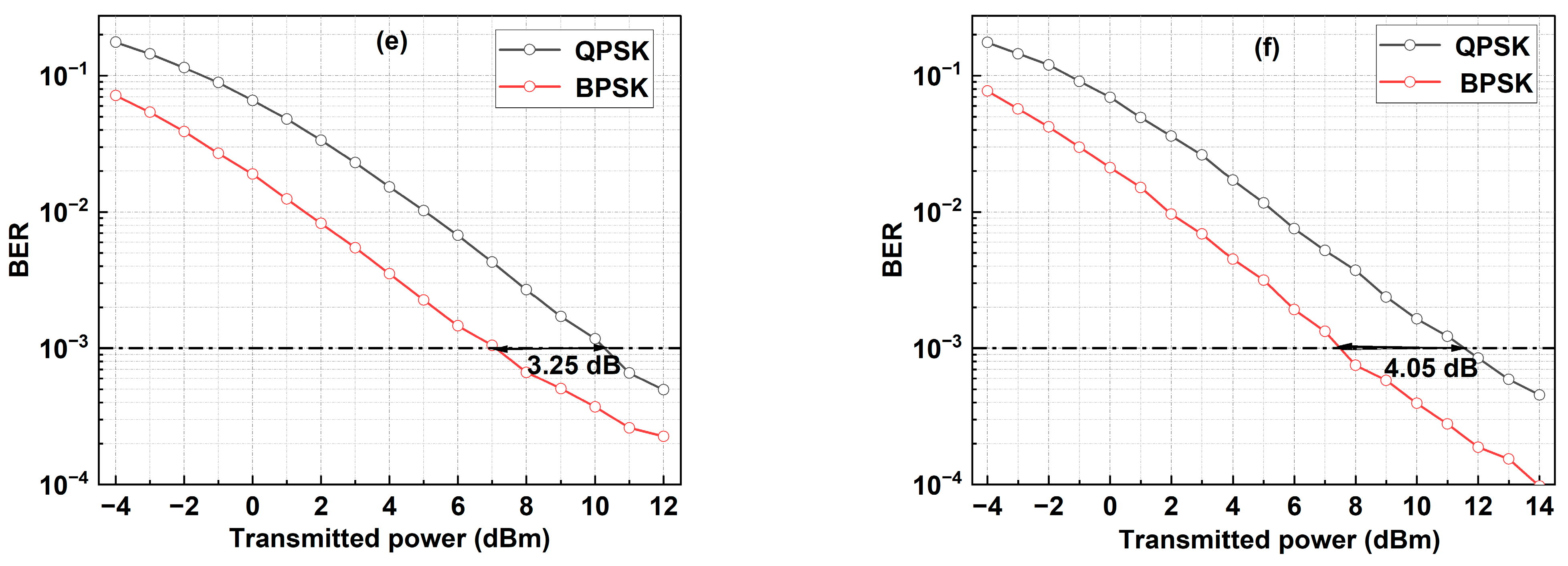
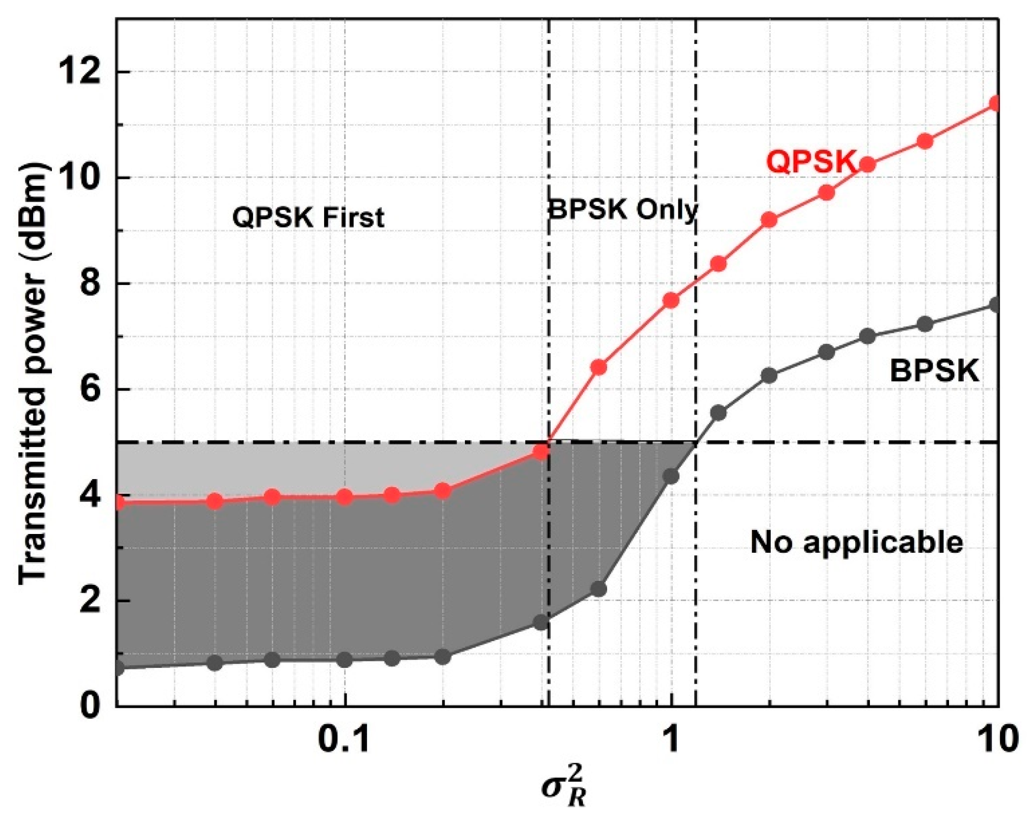
In our experiment, the transmission performance is measured for the atmospheric condition of the Rytov variance of 0.4665. In order to obtain the switching basis, more BER performances under different atmospheric conditions are required. As shown in Figure 5, the BER curves are simulated as the transmitted power with different values of . Figure 5a,b show the BER curves for the QPSK and BPSK signals under weak turbulences. At the BER of 1 × 10⁻³, the required transmitted power is 3.96 dBm and 0.88 dBm, respectively when the Rytov variance is 0.0199, while these are 4.01 dBm and 0.91 dBm when the Rytov variance increases to 0.0995. Under moderate turbulences shown in Figure 5c,d, the transmitted powers of 4.82 dBm for the QPSK signal and 1.59 dBm for the BPSK signal are required for the Rytov variance of 0.3982. On the other hand, they increase to 7.68 dBm and 4.35 dBm when the Rytov variance increases to 0.9955. In Figure 5e,f for strong turbulences, the transmitted power required for the QPSK and BPSK signals rises to 10.25 dBm and 7.00 dBm (11.55 dBm and 7.50 dBm) for the Rytov variance of 3.9819 (9.9548). As shown in Figure 6, the power penalty of the QPSK signal is about 3–4 dB compared to the BPSK signal, which provides the possibility of improving the comprehensive performance, considering both capacity and quality by switching the modulation format between QPSK and BPSK.

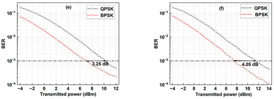
Figure 5.
Simulated BER results of the QPSK and BPSK signals under different turbulence conditions of (a) = 0.0199, (b) = 0.0995, (c) = 0.3982, (d) = 0.9955, (e) = 3.9819, and (f) = 9.9548.

Figure 6.
Measurement of the transmitted power for reaching the BER threshold of QPSK and BPSK signals under different turbulence conditions.
In Figure 6, the required transmitted powers are obtained for the certain BER of 1 × 10⁻³ under different atmospheric turbulences. The simulation results are summarized in Figure 6, where the variation of the BER is plotted against the transmitted power by fixing the BER at 1 × 10⁻³. It can be seen that the required transmitted power for the QPSK signal is higher than that of the BPSK signal. However, the QPSK signal can transmit more data since each symbol carries multiple bits. Therefore, the QPSK signal is preferred for use if the communication performance can be ensured. For a real FSO link, the transmitted power that can be provided by the optical carrier is always limited. Assuming that the maximum permitted transmitted power is 5 dBm, the range of the Rytov variance that can be supported by the QPSK is obtained as 0–0.4624 to ensure the required BER. However, the range is enhanced to 0–1.1858 for the BPSK signal. As a result, when the Rytov variance ranges from 0 to 0.4624, both BPSK and QPSK signals can be selected and the QPSK signal is preferred for improvement of the capacity. When ranges from to , only BPSK can meet the BER requirement. When exceeds , neither QPSK nor BPSK can meet the BER requirement of 1 × 10⁻³ under the given transmitted power.
6. Conclusions
An all-in-one BPSK/QPSK switchable transmission and reception method has been proposed and experimentally demonstrated for adaptive FSO communication links. Using the same series of transmitter and receiver, both the QPSK and BPSK are generated and the transmission performances are measured via a rotating phase plate simulating the atmospheric channel. Experimental and simulation results show that the QPSK signal performance is lower than the BPSK signal and the power penalty is about 3–4 dB at the BER of 1 × 10⁻³. By simulating the required transmitted power to ensure the BER performance, a suitable Rytov variance range is obtained for the BPSK and QPSK signals. Furthermore, the switching criteria is determined as the atmospheric environment varies. In a real BPSK/QPSK switchable FSO transmission system, the atmospheric environment can be real-time monitored to evaluate the channel condition. The required modulation formats will be selected according to the switching criteria. Then, the transmitter and receiver will be switched to the suitable operating mode in order to realize the format transmission. The switching can be real-time realized in the future to keep the link performance stable. Moreover, it is also possible to select higher-order modulation formats to further improve the communication capacity. Our proposed switchable BPSK/QPSK FSO transmission technology may have potentially in real FSO communication systems of the future.
Author Contributions
Conceptualization, Y.C., C.M., K.X., S.G., Q.J. and H.Y.; Formal analysis, S.G., Q.J. and H.Y.; Funding acquisition, Z.L. and K.D.; Investigation, C.M.; Methodology, Y.C., C.M., K.X. and S.G.; Project administration, Z.L. and K.D.; Resources, K.D.; Software, Y.C. and K.X.; Supervision, S.G. and Z.L.; Writing—original draft, Y.C.; Writing—review & editing, S.G. All authors have read and agreed to the published version of the manuscript.
Funding
This work was supported by the National Natural Science Foundation of China (U2141231, 62375239, 62105042) and the Zhejiang Provincial Natural Science Foundation (LDT23F04015F05).
Institutional Review Board Statement
Not applicable.
Informed Consent Statement
Not applicable.
Data Availability Statement
Data are contained within the article.
Acknowledgments
The authors acknowledge the valuable comments of the reviewers and editors.
Conflicts of Interest
The authors declare no conflict of interest.
References
- Vineeth, P.; Jagadeesh, V.; Palanivel, M. Asymptotic bit error rate analysis of free space optical systems using spatial diversity. Opt. Commun. 2018, 427, 617–621. [Google Scholar]
- Chowdhury, M.Z.; Hossan, M.T.; Islam, A.; Jang, Y.M. A Comparative Survey of Optical Wireless Technologies: Architectures and Applications. IEEE Access 2018, 6, 9819–9840. [Google Scholar] [CrossRef]
- Yao, H.; Ni, X.; Chen, C. Performance of M-PAM FSO communication systems in atmospheric turbulence based on APD detector. Opt. Express 2018, 26, 23819–23830. [Google Scholar] [CrossRef] [PubMed]
- Andrews, L.C.; Phillips, R.L. Laser Beam Propagation through Random Media; SPIE Digital Library: Bellingham, WA, USA, 2005; pp. 1–783. [Google Scholar]
- Savory, S.J. Digital coherent optical receivers: Algorithms and subsystems. IEEE J. Sel. Top. Quantum Electron. 2010, 16, 1164–1179. [Google Scholar] [CrossRef]
- Hatef, N.; Murat, U. Experimental investigation on the effect of wavelength on aperture averaging in FSO communications. Opt. Lett. 2020, 45, 3063–3066. [Google Scholar]
- Weeks, A.R.; Xu, J.; Phillips, R.R.; Andrews, L.C.; Stickley, C.M.; Sellar, G.; Stryjewski, J.S.; Harvey, J.E. Experimental verification and theory for an eight-element multiple-aperture equal-gain coherent laser receiver for laser communications. Appl. Opt. 1998, 37, 4782–4788. [Google Scholar] [CrossRef] [PubMed]
- Tyson, R.K. Bit-error rate for free-space adaptive optics laser communications. J. Opt. Soc. Am. A 2002, 19, 753–758. [Google Scholar] [CrossRef] [PubMed]
- El-Nahal, F.I. Coherent quadrature phase shift keying optical communication systems. Optoelectron. Lett. 2018, 14, 372–375. [Google Scholar] [CrossRef]
- Wu, W.; Chen, M.; Zhang, Z. Overview of deep space laser communication. Sci. China Inf. Sci. 2018, 61, 040301. [Google Scholar] [CrossRef]
- Goldsmith, A. Adaptive modulation and coding for fading channels. In Proceedings of the 1999 IEEE Information Theory and Communications Workshop (Cat. No. 99EX253), Kruger National Park, South Africa, 25 June 1999; pp. 24–26. [Google Scholar]
- Elamassie, M.; Uysal, M. Feedback-free adaptive modulation selection algorithm for FSO systems. IEEE Wirel. Commun. Lett. 2021, 10, 1964–1968. [Google Scholar] [CrossRef]
- Lei, W. Mode Selection Threshold in Adaptive Modulation Coding Technology for Atmospheric Laser Communication. Laser Optoelectron. Prog. 2017, 54, 117–123. [Google Scholar]
- Jaiswal, A.; Jain, V.K.; Kar, S. Adaptive coding and modulation (ACM) technique for performance enhancement of FSO Link. In Proceedings of the 2016 IEEE First International Conference on Control, Measurement and Instrumentation (CMI), Kolkata, India, 8–10 January 2016; pp. 53–55. [Google Scholar]
- Wang, X.; Feng, X.; Huang, L.; Guo, C.; Hong, X.; Gao, S. Integrated wavelength conversion for adaptively modulated WDM-OFDM signals in a silicon waveguide. Opt. Express 2017, 25, 31417–31422. [Google Scholar] [CrossRef]
- Wang, S.; Feng, X.; Gao, S.; Shi, Y.; Dai, T.; Yu, H.; Tsang, H.; Dai, D. On-chip reconfigurable optical add-drop multiplexer for hybrid wavelength/mode-division-multiplexing systems. Opt. Lett. 2017, 42, 2802–2805. [Google Scholar] [CrossRef]
- Su, J. Real-time 15GBaud QPSK and 16QAM Flexible Coherent Optical Receiver Implemented on a Single FPGA Chip with Low Complexity DSP. In Proceedings of the 2023 4th Information Communication Technologies Conference (ICTC), Nanjing, China, 17–19 May 2023; pp. 183–188. [Google Scholar]
- Wang, T.; Zhang, A.; He, Y. MZM Bias Voltage Control Algorithms Based on Partial Differential Processing. Space Electron. Technol. 2019, 16, 28–32. [Google Scholar]
- Lan, F.; Han, T.; Guo, J. Multi-format Optical Modulation Technique with High Bit Rate for Space Laser Communication. Semicond. Optoelectron. 2020, 41, 884–888. [Google Scholar]
- Zhao, H.; Zhang, P.; Yang, Z. Simulation and Experimental Research of Multimodulation Format Compatible Space Laser High-Speed Communication Modulation. Chin. J. Lasers 2022, 49, 113–123. [Google Scholar]
- Benbaghdad, M.; Taloul, S.; Tedjini, S. Real Time Implementation of Automatic Digital Modulation-Based SNR Estimation Using SDR Platforms. Wirel. Pers. Commun. 2023, 132, 1593–1612. [Google Scholar] [CrossRef]
- Alathwary, W.A.; Altubaishi, E.S. Performance of coherent FSO systems with adaptive M-PSK modulation. Opt. Laser Technol. 2024, 168, 109990. [Google Scholar] [CrossRef]
- Mecozzi, A.; Antonelli, C.; Shtaif, M. Kramers–Kronig coherent receiver. Optica 2016, 3, 1220–1227. [Google Scholar] [CrossRef]
- Xue, M.; Pan, S.; Zhao, Y. Optical Single-Sideband Modulation Based on a Dual-Drive MZM and a 120° Hybrid Coupler. J. Light. Technol. 2014, 32, 3317–3323. [Google Scholar] [CrossRef]
- Yu, J. Photonics-Assisted Millimeter-Wave Wireless Communication. IEEE J. Quantum Electron. 2017, 53, 1–17. [Google Scholar] [CrossRef]
- Navidpour, S.M.; Uysal, M.; Kavehrad, M. BER Performance of Free-Space Optical Transmission with Spatial Diversity. IEEE Trans. Wirel. Commun. 2007, 6, 2813–2819. [Google Scholar] [CrossRef]
- Zhang, J.; Ding, S.; Zhai, H.; Dang, A. Theoretical and experimental studies of polarization fluctuations over atmospheric turbulent channels for wireless optical communication systems. Opt. Express 2014, 22, 32482–32488. [Google Scholar] [CrossRef]
- Davis, J.A.; McNamara, D.E.; Cottrell, D.M.; Sonehara, T. Two-dimensional polarization encoding with a phase-only liquid-crystal spatial light modulator. Appl. Opt. 2000, 39, 1549–1554. [Google Scholar] [CrossRef]
- Strasburg, J.D.; Harper, W.W. Impact of atmospheric turbulence on beam propagation. In Laser Systems Technology II; SPIE Digital Library: Bellingham, WA, USA, 2004; Volume 5413, pp. 93–102. [Google Scholar]
- Klug, A.; Peters, C.; Forbes, A. Robust structured light in atmospheric turbulence. Adv. Photonics 2023, 5, 016006. [Google Scholar] [CrossRef]
Disclaimer/Publisher’s Note: The statements, opinions and data contained in all publications are solely those of the individual author(s) and contributor(s) and not of MDPI and/or the editor(s). MDPI and/or the editor(s) disclaim responsibility for any injury to people or property resulting from any ideas, methods, instructions or products referred to in the content. |
© 2024 by the authors. Licensee MDPI, Basel, Switzerland. This article is an open access article distributed under the terms and conditions of the Creative Commons Attribution (CC BY) license (https://creativecommons.org/licenses/by/4.0/).