High-Efficiency 4 × 4 × 10 Gbps Orbital Angular Momentum Modes Incorporated into Satellite–Ground–Underwater Optical Wireless System under Diverse Turbulences


Abstract
:1. Introduction
2. Related Work
- A high-speed, high-capacity, and long-reach satellite–ground–underwater OAM-based OWC communication system is designed.
- System performance is analyzed for satellite-to-ground and ground-to-underwater communication under diverse climate conditions and different OAM modes.
- System performance is verified w.r.t. another recent works.
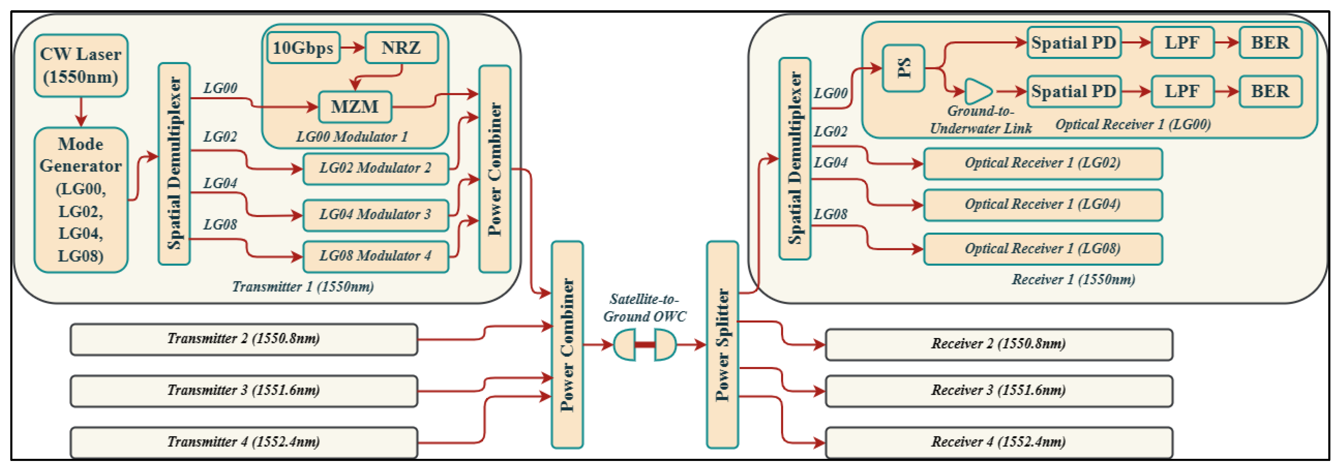
3. Proposed Design
3.1. Space-to-Ground Atmospheric Model
3.2. Ground-to-Underwater Channel Model
4. Results and Discussion
5. Conclusions
Author Contributions
Funding
Institutional Review Board Statement
Informed Consent Statement
Data Availability Statement
Conflicts of Interest
References
- Aboelala, O.; Lee, I.E.; Chung, G.C. A Survey of Hybrid Free Space Optics (FSO) Communication Networks to Achieve 5G Connectivity for Backhauling. Entropy 2022, 24, 1573. [Google Scholar] [CrossRef]
- Kumar, N.; Rana, D.R. Enhanced Performance Analysis of Inter-Aircraft Optical-Wireless Communication (IaOWC) System. Opt. Int. J. Light Electron Opt. 2014, 125, 486–488. [Google Scholar] [CrossRef]
- Li, C.Y.; Huang, X.H.; Lu, H.H.; Huang, Y.C.; Huang, Q.P.; Tu, S.C. A WDM PAM4 FSO-UWOC Integrated System with a Channel Capacity of 100 Gb/S. J. Light. Technol. 2020, 38, 1766–1776. [Google Scholar] [CrossRef]
- Shukla, A.M.; Gupta, S. Joint WDM and OAM Mode Group Multiplexed Transmission Over Conventional Multimode Fiber. IEEE Photonics J. 2023, 15, 7201109. [Google Scholar] [CrossRef]
- Rjeb, A.; Seleem, H.; Fathallah, H.; Machhout, M. Design of 12 OAM-Graded Index Few Mode Fibers for next Generation Short Haul Interconnect Transmission. Opt. Fiber Technol. 2020, 55, 102148. [Google Scholar] [CrossRef]
- Nejad, R.M.; Allahverdyan, K.; Vaity, P.; Amiralizadeh, S.; Brunet, C.; Messaddeq, Y.; LaRochelle, S.; Rusch, L.A. Mode Division Multiplexing Using Orbital Angular Momentum Modes Over 1.4-Km Ring Core Fiber. J. Light. Technol. 2016, 34, 4252–4258. [Google Scholar] [CrossRef]
- Jahid, A.; Alsharif, M.H.; Hall, T.J. A Contemporary Survey on Free Space Optical Communication: Potentials, Technical Challenges, Recent Advances and Research Direction. J. Netw. Comput. Appl. 2022, 200, 103311. [Google Scholar] [CrossRef]
- Dutta, B.; Sarkar, N.; Atta, R.; Kuiri, B.; Sekhar, A. 1600 Gbps PAM-4 FSO Link Enabled Using OFCL-Based WDM and OAM-Multiplexing Techniques. Results Opt. 2022, 9, 100287. [Google Scholar] [CrossRef]
- Ding, Q.; Zheng, L.; Liu, H.; Li, J.; Guo, X.; Cheng, X.; Dai, Z.; Yang, Q.; Li, J. Design and Performance Analysis of Hybrid Multidimensional OAM-DM-WDM-OFDM-PON System with High-Capacity and Long-Distance Transmission. Photonics 2022, 9, 448. [Google Scholar] [CrossRef]
- Yang, M.; Wang, H.; Wang, L.; Shen, L.; Zhang, L.; Luo, J.; Du, J.; Wang, J. MIMO-Free OAM-MDM Transmission with a Ring-Core Fiber Recirculation Loop. Opt. Fiber Technol. 2023, 81, 103552. [Google Scholar] [CrossRef]
- Song, H.; Su, X.; Song, H.; Zhang, R.; Zhao, Z.; Hu, N.; Zou, K.; Zhou, H.; Pang, K.; Liu, C.; et al. Simultaneous Turbulence Mitigation and Channel Demultiplexing Using a Single Multi-Plane Light Convertor for a Free-Space Optical Link with Two 100-Gbit/s OAM Channels. Opt. Commun. 2021, 501, 127359. [Google Scholar] [CrossRef]
- Banawan, M.; Mishra, S.K.; Gouin, A.; Bacon, N.; Guan, X.; Wang, L.; LaRochelle, S.; Rusch, L.A. Using Standard 2 × 2 MIMO to Increase Capacity of Spatial Multiplexing with OAM Modes. J. Light. Technol. 2023, 41, 1974–1984. [Google Scholar] [CrossRef]
- Fang, Y.; Yu, J.; Chi, N.; Zhang, J.; Xiao, J. A Novel PON Architecture Based on OAM Multiplexing for Efficient Bandwidth Utilization. IEEE Photonics J. 2015, 7, 1–6. [Google Scholar] [CrossRef]
- Atta, R.; Sarkar, N.; Dutta, B.; Sekhar Patra, A. A 40-Gbps Fiber-FSO Convergent Transmission System Employing OFCL-Based WDM and External Modulation Technique. Results Opt. 2023, 11, 100421. [Google Scholar] [CrossRef]
- Weng, Y.; Guo, Y.; Alkhazragi, O.; Ng, T.K.; Guo, J.-H.; Ooi, B.S. Impact of Turbulent-Flow-Induced Scintillation on Deep-Ocean Wireless Optical Communication. J. Light. Technol. 2019, 37, 5083–5090. [Google Scholar] [CrossRef]
- Lv, Z.; He, G.; Qiu, C.; Liu, Z. Investigation of Underwater Wireless Optical Communications Links With Surface Currents Surface Currents and Tides for Oceanic Signal Transmission. IEEE Photonics J. 2021, 13, 1–8. [Google Scholar] [CrossRef]
- Lu, I.C.; Liu, Y.L. 205 Mb/s LED-Based Underwater Optical Communication Employing OFDM Modulation. In Proceedings of the 2018 OCEANS—MTS/IEEE Kobe Techno-Oceans, OCEANS—Kobe 2018, Kobe, Japan, 28–31 May 2018; IEEE: Piscataway Township, NJ, USA, 2018; Volume 1, pp. 1–4. [Google Scholar]
- Kumari, M. Performance Analysis of High Speed Hybrid PON-VLC for Long-Reach Land-to-Underwater Applications. Wirel. Netw. 2023, 29, 1721–1735. [Google Scholar] [CrossRef]
- Huang, Z.; Wang, Z.; Huang, M.; Li, W.; Lin, T.; He, P.; Ji, Y. Hybrid Optical Wireless Network for Future SAGO-Integrated Communication Based on FSO/VLC Heterogeneous Interconnection. IEEE Photonics J. 2017, 9, 7902410. [Google Scholar] [CrossRef]
- Singh, M.; Malhotra, J. Long-Reach High-Capacity Hybrid MDM-OFDM-FSO Transmission Link Under the Effect of Atmospheric Turbulence. Wirel. Pers. Commun. 2019, 107, 1549–1571. [Google Scholar] [CrossRef]
- Kachhatiya, V.; Prince, S. Four-Fold Increase in Users of Time-Wavelength Division Multiplexing (TWDM) Passive Optical Network (PON) by Delayed Optical Amplitude Modulation (AM) Upstream. Opt. Fiber Technol. 2016, 32, 71–81. [Google Scholar] [CrossRef]
- Grover, A.; Sheetal, A.; Dhasarathan, V. Performance Analysis of Mode Division Multiplexing Based Free Space Optics System Incorporating on–off Keying and Polarization Shift Keying under Dynamic Environmental Conditions. Wirel. Netw. 2020, 26, 3439–3449. [Google Scholar] [CrossRef]
- Srivastava, V.; Mandloi, A.; Soni, G.G. Outage Probability and Average BER Estimation of FSO System Employing Wavelength Diversity. Opt. Quantum Electron. 2019, 51, 229. [Google Scholar] [CrossRef]
- Murshid, S.H. Optical Fiber Multiplexing and Emerging Techniques: SDM and OAM; Morgan & Claypool Publishers: San Rafael, CA, USA, 2018; ISBN 9781681745695. [Google Scholar]
- Pesek, P.; Zvanovec, S.; Chvojka, P.; Ghassemlooy, Z.; Haigh, P.A. Demonstration of a Hybrid FSO/VLC Link for the Last Mile and Last Meter Networks. IEEE Photonics J. 2019, 11, 7900307. [Google Scholar] [CrossRef]
- Sarangal, H.; Nisar, K.S.; Thapar, S.S.; Singh, A.; Malhotra, J. Performance Evaluation of 120 GB/s Hybrid FSO-SACOCDMA-MDM System Using Newly Designed ITM-Zero Cross-Correlation Code. Opt. Quantum Electron. 2021, 53, 64. [Google Scholar] [CrossRef]
- Ghazi, A.; Aljunid, S.A.; Idrus, S.Z.S.; Fareed, A.; Al-Dawoodi, A.; Mohsin, A.H. Design of a Hybrid WDMA-Optical-CDMA over Multi-Mode Fiber Transmission System Based on LG Modes for Short Haul-Local Area Network. J. Phys. Conf. Ser. 2021, 1793, 012016. [Google Scholar] [CrossRef]
- Mostafa, S.; Mohamed, A.E.-N.A.; El-Samie, F.E.A.; Rashed, A.N.Z. Performance Evaluation of SAC-OCDMA System in Free Space Optics and Optical Fiber System Based on Different Types of Codes. Wirel. Pers. Commun. 2017, 96, 2843–2861. [Google Scholar] [CrossRef]
- Ghazi, A.; Aljunid, S.A.; Noori, A.; Idrus, S.Z.S.; Rashidi, C.B.M.; Al-Dawoodi, A. Design & Investigation of 10 × 10 Gbit/s MDM over Hybrid FSO Link under Different Weather Conditions and Fiber to the Home. Bull. Electr. Eng. Inform. 2019, 8, 121–126. [Google Scholar] [CrossRef]
- Yeh, C.H.; Lin, W.P.; Luo, C.M.; Xie, Y.R.; Chang, Y.J.; Chow, C.W. Utilizing Single Lightwave for Delivering Baseband/Fso/Mmw Traffics Simultaneously in Pon Architecture. IEEE Access 2019, 7, 138927–138931. [Google Scholar] [CrossRef]
- Ghazi, A.; Aljunid, S.A.; Syed Idrus, S.Z.; Fareed, A.; Rashidi, C.B.M.; Al-Dawoodi, A. Comparison of Laguerre-Gaussian and Hermite-Gaussian Modes for Optical-CDMA over Multi-Mode Fiber. IOP Conf. Ser. Mater. Sci. Eng. 2020, 767, 012011. [Google Scholar] [CrossRef]
- Kumari, M.; Mishra, S.K. Realization of 4 × 200 Gbps 4-QAM OFDM-OWC System Using Higher Order OAM Modes for HAP-to-Satellites Scenario. Photonics 2024, 11, 294. [Google Scholar] [CrossRef]


| Component | Parameters | Value | Unit |
|---|---|---|---|
| CW laser | Wavelength | 1550, 1550.8, 1551.6, 1552.4 | nm |
| Power | 0 | dB | |
| Linewidth | 0.1 | MHz | |
| Azimuth | 45 | deg | |
| OWC channel | Reference wavelength | 1550 | nm |
| Range | 21,000–30,000 | km | |
| Tx and Rx aperture diameter | 15 | cm | |
| Tx and Rx optics efficiency | 0.8 | ||
| Free space path loss | Yes | ||
| Geometric gain | Yes | ||
| Tx and Rx pointing error | 0.1 | µrad | |
| Additional losses | 0 | dB | |
| UWOC link | Wavelength | 1550, 1550.8, 1551.6, 1552.4 | nm |
| Range | 5–30 | m | |
| Geometrical loss and gain | Yes | A/W | |
| Scintillation model | Gamma–Gamma | ||
| Aperture diameter | 15 | cm | |
| Beam divergence | 2 | mrad | |
| Transmitter loss | 0.5 | dB | |
| Optics efficiency | 0.9 | ||
| Spatial PD | PD | PIN | |
| Responsivity | 1 | A/W | |
| Dark current | 9 | nA | |
| Low pass filter | Cut off frequency | 0.75 × Bit rate | Hz |
| Water Type | x(λ) m−1 | y(λ) m−1 | z(λ) m−1 |
|---|---|---|---|
| Pure sea | 0.0405 | 0.0025 | 0.043 |
| Clear ocean | 0.037 | 0.114 | 0.151 |
| Coastal ocean | 0.219 | 0.179 | 0.398 |
| Harbor | 0.913 | 0.187 | 1.1 |
| Turbulence | LG[0,0] | LG[0,2] | LG[0,4] | LG[0,8] |
|---|---|---|---|---|
| km | ||||
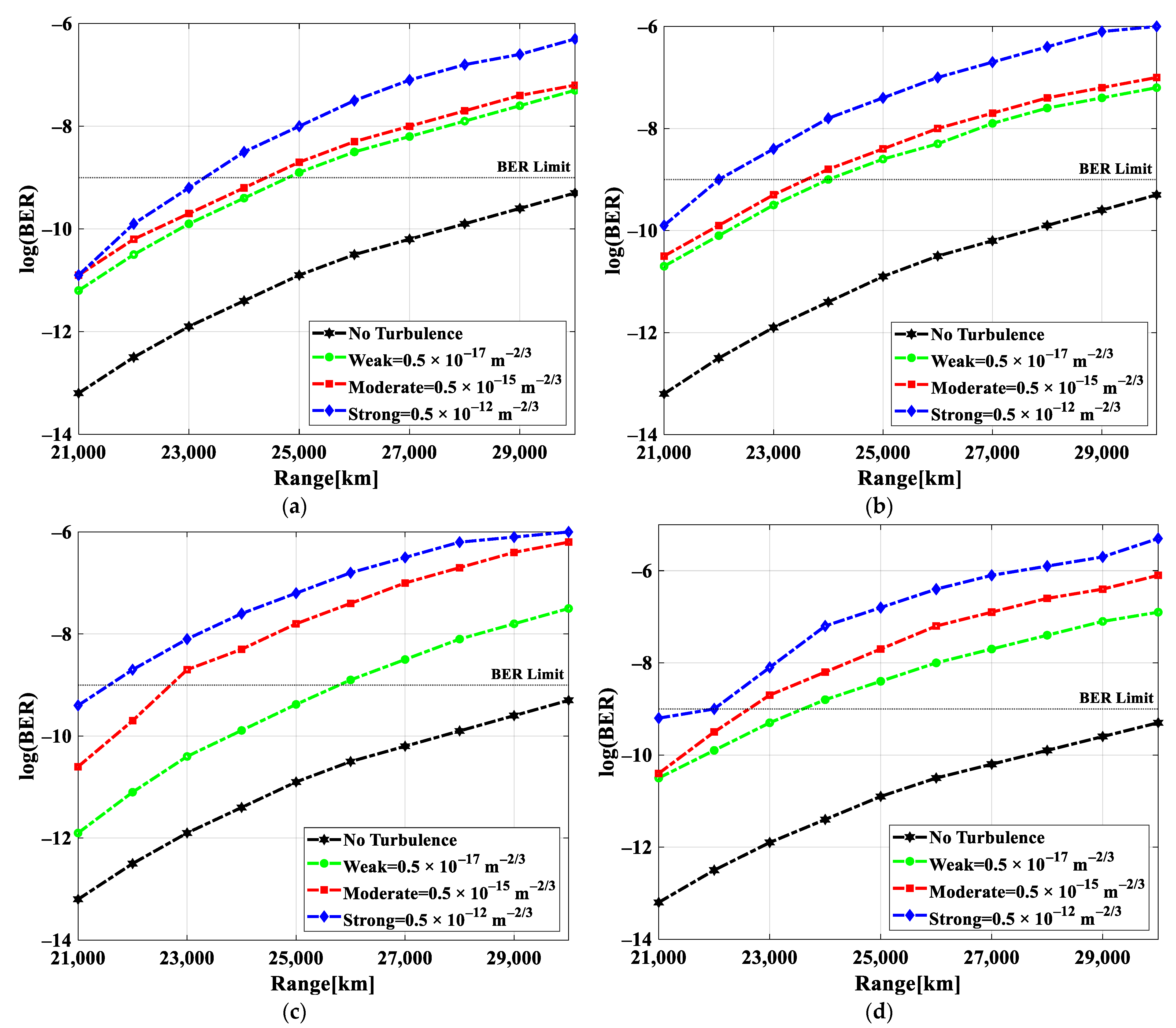
| No | 30,000 | 30,000 | 30,000 | 30,000 |
| Weak | 24,500 | 24,000 | 26,000 | 24,000 |
| Medium | 24,500 | 23,800 | 22,000 | 22,500 |
| Strong | 23,500 | 22,000 | 21,500 | 22,000 |
| Water Type | LG[0,0] | LG[0,2] | LG[0,4] | LG[0,8] |
|---|---|---|---|---|
| m | ||||
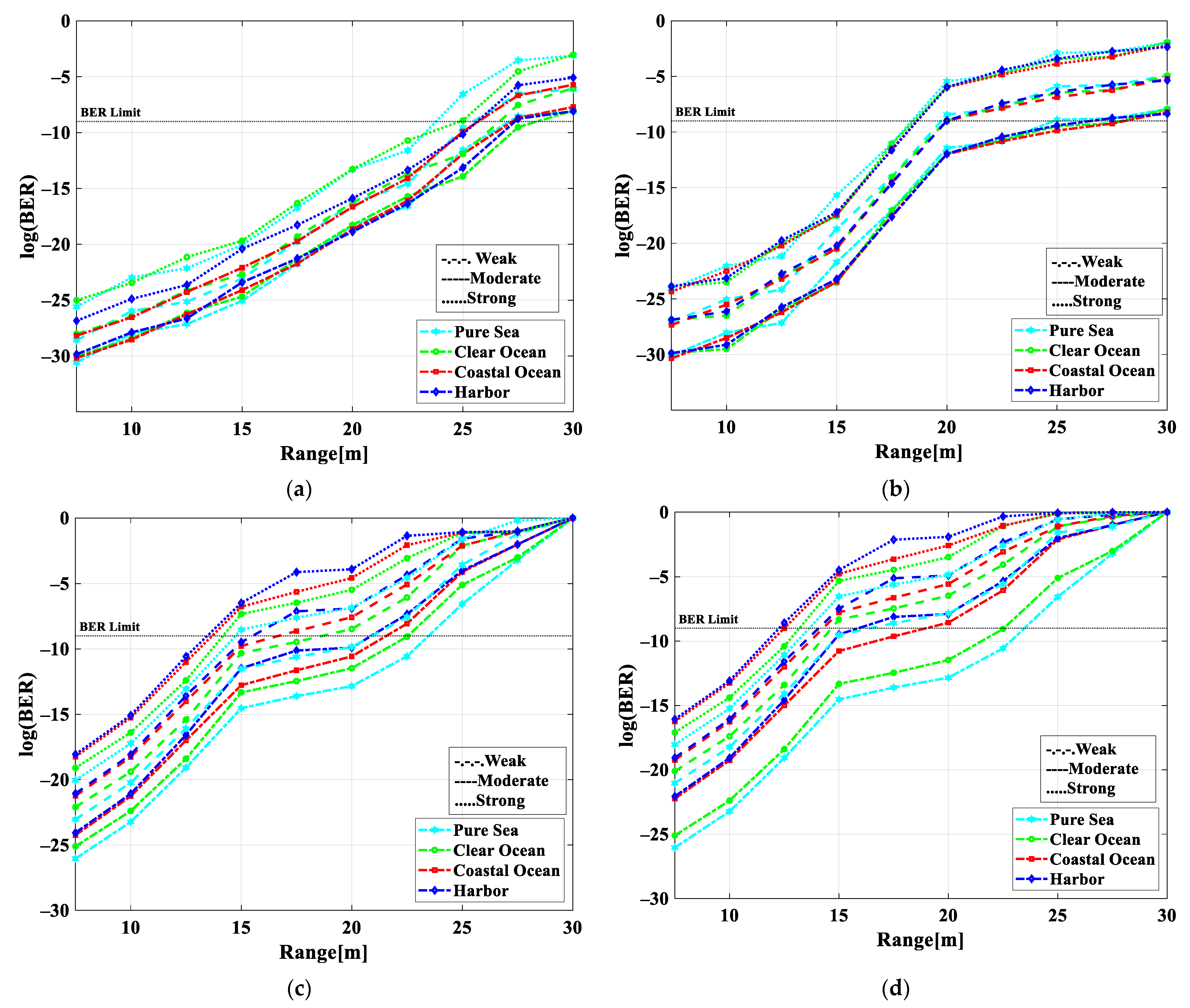
| Pure sea | 27 | 26 | 24 | 23 |
| Clear ocean | 27 | 26 | 24 | 20 |
| Coastal ocean | 27 | 26 | 23 | 17 |
| Harbor | 27 | 26 | 22 | 15 |
| Water Type | LG[0,0] | LG[0,2] | LG[0,4] | LG[0,8] |
|---|---|---|---|---|
| m | ||||
| Pure sea | 26 | 20 | 18 | 15 |
| Clear ocean | 26 | 20 | 18 | 15 |
| Coastal ocean | 26 | 20 | 17 | 14 |
| Harbor | 26 | 20 | 16 | 13 |
| Water Type | LG[0,0] | LG[0,2] | LG[0,4] | LG[0,8] |
|---|---|---|---|---|
| m | ||||
| Pure sea | 25 | 18 | 15 | 14 |
| Clear ocean | 26 | 18 | 15 | 13 |
| Coastal ocean | 25 | 18 | 14 | 12 |
| Harbor | 25 | 18 | 13 | 12 |
| Range (m) | Gain (dB) | NF (dB) | Input Signal (dB) | Input Noise (dB) | Input SNR (dB) | Input OSNR (dB) | Output Signal (dB) | Output SNR (dB) | Output OSNR (dB) |
|---|---|---|---|---|---|---|---|---|---|
| 5 | −75.02 | 75.02 | −3.30 | −81.17 | 77.87 | 79.91 | −78.32 | 21.67 | 21.67 |
| 10 | −75.30 | 75.30 | −3.31 | −81.24 | 77.92 | 79.96 | −78.62 | 21.37 | 21.37 |
| 15 | −75.64 | 75.64 | −3.32 | −81.26 | 77.94 | 79.98 | −78.97 | 21.02 | 21.02 |
| 20 | −75.95 | 75.95 | −3.30 | −81.20 | 77.90 | 79.94 | −79.25 | 20.74 | 20.74 |
| 25 | −76.22 | 76.22 | −3.31 | −81.23 | 77.91 | 79.95 | −79.54 | 20.45 | 20.45 |
| 30 | −76.44 | 76.44 | −3.30 | −81.19 | 77.88 | 79.92 | −79.75 | 20.24 | 20.24 |
| 35 | −76.77 | 76.77 | −3.32 | −81.28 | 77.95 | 79.99 | −80.10 | 19.89 | 19.89 |
| 40 | −76.99 | 76.99 | −3.31 | −81.31 | 77.99 | 80.03 | −80.31 | 19.68 | 19.68 |
| 45 | −77.29 | 77.29 | −3.31 | −81.15 | 77.83 | 79.87 | −80.60 | 19.39 | 19.39 |
| 50 | −77.53 | 77.53 | −3.31 | −81.27 | 77.96 | 80.00 | −80.84 | 19.15 | 19.15 |
| Ref. | No. of Modes | Mode | Data Rate (Gbps) | Wireless Range (m) | Turbulent Condition | Underwater Link | No. of Chansnels | SNR (dB) | BER |
|---|---|---|---|---|---|---|---|---|---|
| [25] | Not used | Not used | 0.0126 | 500 k | Weak, moderate, and strong | Not used | 2 | Not defined | 10−3 |
| [26] | 2 | 00, 01 | 20 | 1750 k | Not defined | Not used | 6 | Not defined | 10−9 |
| [27] | 4 | 01, 02, 03, 04 | 2.488 | Not used | Not used | Not used | 4 | Not defined | 10−9 |
| [23] | Not used | Not used | Not defined | 1.5 k | Weak–strong | Not used | Not defined | 36 | 10−3 |
| [28] | Not used | Not used | 0.622 | 500 k | Moderate | Not used | 3 | 22 | 10−9 |
| [29] | 9 | 00, 01, 02, 10, 11, 12, 20, 22, 21 | 10 | 3200 k | Not defined | Not used | 10 | Not defined | 10−9 |
| [30] | Not used | Not used | 10 | 160 k | Not used | Not used | Not defined | Not defined | 10−9 |
| [31] | 3 | 01, 02, 03 | 1.866 | Not used | Not used | Not used | 3 | Not defined | 10−9 |
| This work | 4 | 0,0; 0,2; 0,4; 0,8 | 160 | 36,000 k + 50 | Weak to strong | Yes (Pure sea, clear ocean, costal ocean, harbor) | 4 | 21.67 | 10−3 |
Disclaimer/Publisher’s Note: The statements, opinions and data contained in all publications are solely those of the individual author(s) and contributor(s) and not of MDPI and/or the editor(s). MDPI and/or the editor(s) disclaim responsibility for any injury to people or property resulting from any ideas, methods, instructions or products referred to in the content. |
© 2024 by the authors. Licensee MDPI, Basel, Switzerland. This article is an open access article distributed under the terms and conditions of the Creative Commons Attribution (CC BY) license (https://creativecommons.org/licenses/by/4.0/).
Share and Cite
Kumari, M.; Mishra, S.K. High-Efficiency 4 × 4 × 10 Gbps Orbital Angular Momentum Modes Incorporated into Satellite–Ground–Underwater Optical Wireless System under Diverse Turbulences. Photonics 2024, 11, 355. https://doi.org/10.3390/photonics11040355
Kumari M, Mishra SK. High-Efficiency 4 × 4 × 10 Gbps Orbital Angular Momentum Modes Incorporated into Satellite–Ground–Underwater Optical Wireless System under Diverse Turbulences. Photonics. 2024; 11(4):355. https://doi.org/10.3390/photonics11040355
Chicago/Turabian StyleKumari, Meet, and Satyendra K. Mishra. 2024. "High-Efficiency 4 × 4 × 10 Gbps Orbital Angular Momentum Modes Incorporated into Satellite–Ground–Underwater Optical Wireless System under Diverse Turbulences" Photonics 11, no. 4: 355. https://doi.org/10.3390/photonics11040355