Abstract
Anti-resonant fiber (ARF) works well in a relatively strong magnetic field due to its weak Faraday effect, which results from the fundamental mode mainly transmitting in the air core. Accurately measuring the Faraday effect strength, i.e., the effective Verdet constant, of an ARF determines its applicable scenarios. However, the effective Verdet constant of ARF is ~3 orders of magnitude lower than that of a standard single-mode fiber, which is very difficult to measure. In this paper, we reveal that intermodal interference is the main obstacle to measuring the ultralow effective Verdet constant of ARF and propose using a narrow-band low-coherence light to suppress it. The measured effective Verdet constant of ARF is 0.423 ± 0.005 mrad/T/m at 1550 nm.
1. Introduction
In recent years, anti-resonant fiber (ARF) has attracted a lot of attention due to its excellent potential and performance and has shown good application prospects in the field of optical communication and optical sensing [1,2]. ARF has a multilayer tubular cladding structure [3] with a low-index region in the core and a tube ring in the cladding region [4]. The transmitted beam is guided in the air core by an anti-resonance effect within the glass film surrounding the core [5]. This structure reduces the confinement loss and allows most of the light to be transmitted in the air core. ARF has a wide range of applications, such as high-power lasers [6], photothermal spectroscopy [7,8], and high-precision sensors [1,9], due to 99.9% of the light propagating in the air core. This unique property also gives ARF weak Faraday effect strength (i.e., the actual measured uncorrected Verdet constant, defined in this paper as the effective Verdet constant), making it work well in a relatively strong magnetic field [10]. The application of ARF in a fiber-optic gyroscope (FOG) can suppress the phase error caused by the Faraday effect [11,12], and may replace the bulky magnetic shield structure [13], which helps to improve the accuracy of the FOG and achieve miniaturization of the FOG.
The Verdet constant of optical fiber is usually measured with the balanced polarization method [14]. For fibers with a high Verdet constant of >500 mrad/T/m [15], such as standard single-mode fiber, spun fiber [16], or europium-doped silica fiber [17], the Verdet constant measurement accuracy can be ~10 mrad/T/m. To measure fiber with a small Verdet constant of ~10 mrad/T/m, such as photonic bandgap fiber, one can use the lock-in detection method to improve the accuracy to 0.3 mrad/T/m [18]. However, there is no reported method to measure the Verdet constant of ARF because the predicted Verdet constant is only about 0.3 mrad/T/m.
When ARF is spliced to a solid core fiber, the high-order mode will excite the fiber to produce intermodal interference, resulting in excessive intensity fluctuation noise at the fiber output [19]. Because the coherence length of the light source is inversely proportional to the bandwidth, it is possible to reduce the intensity fluctuation noise caused by intermodal interference effectively by enlarging the bandwidth of the light source.
In this paper, we reveal that intermodal interference is the main obstacle to measuring the ultralow Verdet constant of ARF and propose using a narrow-band low-coherence light to suppress it. We demonstrate that the Verdet constant sensitivity of our measurement system is <0.3 mrad/T/m by using either a narrow-band low-coherence light or a narrow-linewidth laser light when measuring the air optical path. Nevertheless, for the ARF-45-240 fiber (IXblue Photonics, Paris, France), we obtain an effective Verdet constant of ~0.4 mrad/T/m by only using the narrow-band low-coherence light.
2. Theory
Based on the magneto-optical Faraday effect, a magnetic field causes the polarization rotation of light with a rotation angle that is expressed as [20]
where L is the length of the fiber sample under test, B(l) is the magnetic field projection along the fiber direction, and V(λ) is the Verdet constant of the fiber sample that depends on the light wavelength λ.
A schematic diagram of the Verdet constant measurement for ARF is shown in Figure 1. Assuming that the intensity of the injected light is I0, the light intensity of P polarization and S polarization at the detector can be expressed as [21]
where α is the initial polarization angle, and θ is the rotation angle due to the Faraday effect. Since the sinusoidal AC magnetic field can be expressed as B = B0sin(ωst + φ0), and θ is proportional to B, the Faraday rotation angle can be described as θ = θ0sin(ωst + φ0). When the initial polarization angle is α = 45°, we can obtain an intensity-independent quantity, namely the T-parameter, that is expressed as
where θ0 is the Faraday rotation angle, ωs is the modulated signal frequency, and φ0 is the initial phase. It can be seen from the formula that compared with the rotating polarization method (based on two cross polarizers) [22], the balanced polarization method has the advantage of eliminating the influence of light source intensity fluctuation on the measurement results and improving the accuracy of the measurement results.
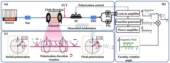
Figure 1.
Schematic diagram of Verdet constant measurement for ARF. (a) Measurement setup based on Faraday effect. (b) Signal–to–noise ratio improvement based on lock–in detection technology. (c) Evolution of Faraday rotation angle. Pol., polarizer; FUT, fiber under test; PC, polarization controller; PBS, polarization beam splitter; PD1 and PD2, photodetector 1 and photodetector 2; LF, low–pass filter; Ep and Es, light amplitude of P polarization and S polarization.
Because the Verdet constant of ARF is very small, we apply sinusoidal field modulation to the measured signal and use the lock-in detection technology to demodulate the signal to improve the signal-to-noise ratio, as shown in Figure 1b. Since the higher-order term of θ is much less than 1, ignoring the higher-order terms about the small θ, we can express the demodulation T-parameter as Tlock-in ≈ |2θ0|.
Therefore, the Verdet constant of the fiber under test is
3. Experimental Setup
The measurement system for measuring the ARF Verdet constant is composed of a light source module, measurement module, driver module, polarization adjustment module, and demodulation module, as shown in Figure 2. A tunable optical filter (Santac, OTF-980, Nagoya, Japan) filters the low-coherence light output from the wide-spectrum light source (Conquer, ASE-CL-D, Beijing, China) to generate a narrow-band low-coherence light that is then successively injected into the isolator (Iso.), the 45° polarizer (Pol.), and the measurement module. The narrow-band low-coherence light with an expanded linewidth suppresses the influence of intensity fluctuation noise caused by the intermodal interference in the ARF on the measurement. The function of the isolator is to prevent the reverse transmission of reflected light in the fiber from affecting the light source.
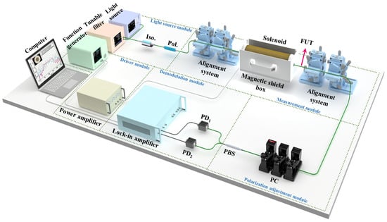
Figure 2.
Experimental configuration of Verdet constant measurement for ARF based on narrow–band low–coherence light. Iso., optical isolator; Pol., polarizer; FUT, fiber under test; PC, polarization controller; PBS, polarization beam splitter; PD1 and PD2, photodetector 1 and photodetector 2.
The measurement module comprises two pairs of six-degree-of-freedom alignment systems, the samples under test, and a magnetic field generation device. We fixed the gradient index lens on the alignment system and used the alignment system to complete the coupling of spatial light. We use a solenoid as a magnetic-field-generation device. In the driver module, the function generator generated two signals. One was input to a power amplifier (YingPu Magnetoelectric, HEAS-20, Changchun, China) as a modulation signal driving the solenoid. The other was fed into a lock-in amplifier (Zurich Instruments, UHFLI-600, Zurich, Switzerland) as a reference signal for the demodulation.
The light output from the device module under test was input to the polarization adjustment module. In the polarization adjustment module, we adjusted the polarization controller (PC) to achieve a polarization balance state of the polarization beam splitter (PBS), i.e., the orthogonal polarization outputs of the PBS were equal, IPD1 = IPD2. The PC (Thorlabs, MPC320, Newton, NJ, USA) was programmable with 3 paddles and a minimum step size of 0.12°. The demodulation module was used to collect the orthogonal polarization light intensity and demodulate the signal without and with the magnetic field effect using the lock-in amplifier. When no magnetic field was applied, the demodulation results of the lock-in amplifier corresponded to the measurement noise at the frequency ωs, that is, the measurement limit of the system. When the magnetic field was loaded, the demodulation results corresponded to the Faraday rotation angle.
4. Experiment Result and Discussion
4.1. System Measurement Sensitivity
To measure the Verdet constant of the fiber, we first needed to measure the magnetic field distribution of the solenoid accurately. The solenoid used had a length of 28 cm, an inner diameter of 1 cm, and an outer diameter of 8 cm. We used a shield box [23] to reduce the magnetic field outside the solenoid and its influence on the measurement accuracy of the Verdet constant. We set the modulation signal frequency to 100 Hz and applied the signal to the solenoid using a power amplifier. The magnetic field distribution of the solenoid was measured at 2 mm intervals with a Gauss meter (CH Magnetoelectricity, CH3600, Beijing, China) starting from the center. The measurement result is shown in Figure 3a. The driving current of the power amplifier recorded at this time was 1.70 A, and the magnetic field integral intensity was 3.31437 × 10⁻³ T·m at 1.70 A and 100 Hz.
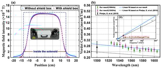
Figure 3.
(a) Comparison of magnetic field distribution results with or without shielding box based on Gauss meter. (b) Measurement results of Verdet constant of air and comparison with other results [24]. (I) Practical experimental device for measuring Verdet constant of air based on a gradient index lens. (II) Linear fitting result of air Verdet constant corresponds to the square of the optical frequency v.
To evaluate the sensitivity of our measurement system, we first measured the Verdet constant of air, whose Verdet constant is known and is reported in the existing literature as sub-mrad/T/m near 1550 nm [24]. We use two gradient index lenses to achieve spatial light coupling, allowing light to be transmitted through air and acted upon by magnetic fields. The actual coupling device is shown in Figure 3(aI). According to the spectral range of the wide-spectrum light, we set the bandwidth of the tunable filter to 1 nm and the drive current of the power amplifier to 1.70 A, and measured every 10 nm interval in the range of 1530–1600 nm using narrow-band low-coherence light. Keeping the same conditions, we took measurements based on a laser source (Santec, TSL-570, Nagoya, Japan) with a linewidth of 100 kHz in the 1525–1605 nm range, with the same wavelength interval of 10 nm for each measurement. Figure 3b shows the measurements of the Verdet constant of air based on two different light sources and a comparison with the other results. Because the Verdet constant is wavelength-dependent (proportional to the square of the optical frequency v) [25], we linearly fit our measurement results (two different light source schemes) based on the square of the optical frequency v, as denoted by the blue line in Figure 3(bII). We also linearly fit the measurement results of earlier scholars [24] based on the square of the optical frequency v, and the fitting curve is denoted by the black dashed line in Figure 3(bII). We measured the Verdet constant of the air at 1550 nm as 0.280 ± 0.013 mrad/T/m, and earlier scholars measured the Verdet constant of the air at 1547 nm as 0.12 ± 0.02 mrad/T/m. The difference between these two measurements is more than double. However, we can clearly see that the measurement results of the early scholars at 1547 nm deviated from their linear fitting curve (i.e., the black dashed line in Figure 3(bII)) by about twice, while our results had good stability, and the measurement results of the early scholars at 1500 nm fell well on the linear fitting curve of our measurement results. The measurement results near 1550 nm in the reference do not conform to the linear fitting curve, which may be due to the extremely low Verdet constant of the air (in the order of sub-mrad/T/m), and the common mode noise in the system (such as solenoid current source noise, detector noise, etc.) is not completely suppressed. Our measurement results of air’s Verdet constant at different wavelengths are in good agreement, and the measurement results of earlier scholars at 1500 nm agree well with the linear fitting curve of our measurement results, which verifies the measurement sensitivity and accuracy of our measurement system.
4.2. The Verdet Constant Measurement of Anti-Resonant Fiber
The main objective of this paper is to measure the Verdet constant of ARF. We compare the effects of different light source schemes on the Verdet constant measurement of ARF, verify the effectiveness of narrow-band low-coherence light, and report the Verdet constant results of ARF under this light source scheme. We achieve ARF coupling through splicing based on a fusion splicer (Fujikura, FSM100P+, Tokyo, Japan). We measured the transmission spectrum of a 2 m long ARF with an optical vector analyzer (LUNA, OVA5100, Virginia, USA) and used the Fourier transform method to obtain the wavenumber distribution of the transmission spectrum. The transmission spectrum of ARF is shown in Figure 4A, and the loss of ARF at 1550 nm is 11.3 dB. The wavenumber distribution of the transmission spectrum of ARF is shown in Figure 4B. In Figure 4B, we can clearly see several different beat frequencies corresponding to the interference between different modes. At this time, the polarization of the total composite mode field is random, and the polarization balance cannot be adjusted by the polarization controller, that is, the intermodal interference noise is introduced. The beam profile of ARF is shown in the inset in Figure 4B. Figure 4C shows a microscope image of the ARF cross-section. The fiber diameter is 240.0 µm, and the cladding diameter is 102.4 µm. The cladding consists of seven tubes with a thickness of 2.3 µm, a tube diameter of 26.4 µm, and an inter-tube gap distance of 6.8 µm. The entire core is filled with air, including the space between and within the silica tubes. In each light source scheme, the final light power output to the detector is guaranteed to be consistent.
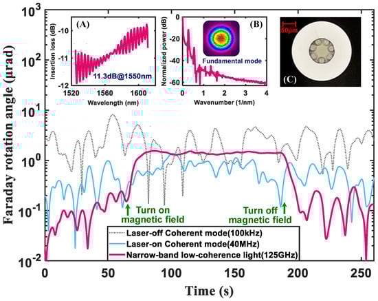
Figure 4.
Comparison of Faraday effect strength results of ARF with linewidths of 100 kHz, 40 MHz, and 125 GHz under consistent optical power and magnetic field intensity (total light intensity: 8 μW; power amplifier drive current: 1.70 A). (A) Transmission spectrum of ARF. (B) Wavenumber distribution of transmission spectrum of ARF. Inset: Beam profile of ARF. (C) Microscope image of ARF cross−section.
We compared the Faraday effect strength of ARF at 1550 nm under three different light source schemes with linewidths of 100 kHz, 40 MHz, and 125 GHz, respectively. The laser source (Santec TSL-570) output a 100 kHz linewidth light when the coherence control was turned off and a 40 MHz linewidth light when the coherence control was turned on. The narrow-band low-coherence light source output a 125 GHz linewidth light when the bandwidth of the tunable filter was set to 1 nm. The polarization balance state was measured for 60 s in each light source scheme. Then, we set the power amplifier drive current to 1.70 A and turned on the magnetic field. In this process, the demodulation results correspond to the Faraday rotation angle. We maintained the magnetic field loading time for 100 s, and then, turned off the magnetic field and measured again for 60 s at the polarization balance state. The measurement results for the three light source schemes are shown in Figure 4. The results show that the Faraday rotation angle of ARF is only about 1.4 μrad at a 1.70 A driven current, and only the narrow-band low-coherence light scheme can effectively suppress the intermodal interference noise and respond to the Verdet constant measurement of ARF.
The Verdet constant of the ARF was then measured based on the narrow-band low-coherence light. We set the center wavelength of the tunable optical filter to 1550 nm and the bandwidth to 1 nm and measured the response of ARF under different magnetic field intensities at about a 0.10 A peak current interval starting from a 0.20 A peak current, keeping each peak current stable for 100 s. Figure 5a shows the variation in the Faraday rotation angle θ with the magnetic field strength. The blue dashed line is the Faraday rotation angle of ARF measured in real time with the change in magnetic field strength. The pink line is the average value of the Faraday rotation angle measured at each stable magnetic field strength. The measurement noise of Faraday rotation mainly comes from the adjustment accuracy of the polarization controller, but also from random weak disturbance in the environment and common noise that is not completely suppressed, such as the detector noise. Figure 5b shows the relationship between the Faraday rotation angle θ and the integral of the magnetic field intensity. The slope of the linear fitting curve of the measurement results represents the effective Verdet constant of the ARF, which is 0.423 ± 0.005 mrad/T/m at 1550 nm.
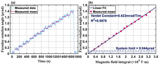
Figure 5.
(a) The measurement results of the Faraday rotation angle of ARF at 1550 nm based on a wide−spectrum light source and tunable filter (Faraday rotation angle increases with time). (b) The relationship between the measured mean value of the Faraday rotation angle of ARF and the integral of the magnetic field intensity of the solenoid. The slope of the fitted curve is the Verdet constant of ARF.
The effective Verdet constant of ARF can be expressed as [26,27]
where η is the optical power proportion transmitted in the silica part of the fiber, VSiO2 is the Verdet constant of silica, and Vair is the Verdet constant of air. Because the Verdet constant of SiO2 is 550 mrad/T/m at 1550 nm, it can be determined that the proportion of light propagating in the air core of the ARF is 99.97%, which conforms to the characteristics of this fiber (its modes overlap with the core at a rate of >99%).
In a ring fiber interferometer, assuming that the influence of the Earth’s magnetic field Bearth is integrated constructively along the whole fiber length L, the maximum non-reciprocal phase difference can be expressed as [28]
where Vfiber is the Verdet constant of the fiber under test. Since Bearth is typically 5 × 10⁻⁵ T, ΔϕFmax is about 0.04 mrad at 1550 nm based on a 1 km ARF coil, which is smaller than the 55 mrad at 1550 nm based on a 1 km single-mode fiber coil. These results show that ARF can effectively suppress the magnetic error in FOG, and has potential application advantages in strong magnetic fields.
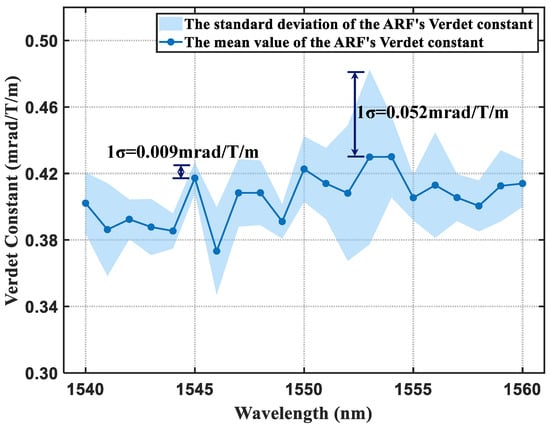
We also measured the effective Verdet constant of ARF in the 1540–1560 nm range, as shown in Figure 6. We set the bandwidth of the tunable filter to 1 nm and the power amplifier drive current to 1.70 A, continuously measuring at 1 nm intervals in the 1540–1560 nm range by changing the center wavelength of the tunable filter. The minimum value of the effective Verdet constant is 0.373 ± 0.026 mrad/T/m at 1546 nm, and the maximum value is 0.430 ± 0.024 mrad/T/m at 1554 nm. The best measurement repeatability of the Verdet constant is 0.009 mrad/T/m at 1545 nm, and the worst is 0.052 mrad/T/m at 1553 nm. The measurement repeatability variation of Verdet constants at different wavelengths results from weak fluctuation in the initial polarization balance state.
5. Conclusions
In conclusion, for the first time (to the best of our knowledge), this paper reports that the effective Verdet constant of ARF is 0.423 ± 0.005 mrad/T/m at 1550 nm. We built a Verdet constant measurement system with a sensitivity of 0.280 mrad/T/m and a repeatability of 0.013 mrad/T/m based on the balanced polarization method combined with lock-in detection technology. However, because of the intermodal interference, the measurement system cannot obtain any Faraday effect response from the ARF when using a laser as the light source. We propose using a narrow-band low-coherence light to suppress the influence of the ARF mode noise and obtain a remarkable Faraday effect response. Finally, the Verdet constants of ARF at various wavelengths were measured. The Verdet constant measurement for ARF provides a basis for analyzing the diamagnetism of ARF and the phase error caused by the Faraday effect in ARF-based fiber-optic gyroscopes.
Author Contributions
Conceptualization, Z.G. and Z.Y.; methodology, Z.Y.; software, Z.G.; validation, Z.G., Y.L. and Z.Y.; formal analysis, Z.G., H.D. and Z.Y.; investigation, H.D.; resources, Z.Y.; writing—original draft preparation, Z.G.; writing—review and editing, Y.L., Z.G. and Z.Y.; visualization, H.D.; supervision, Z.Y.; project administration, Z.Y. All authors have read and agreed to the published version of the manuscript.
Funding
This research was funded by the National Natural Science Foundation of China (62005054), the Guangdong Introducing Leading Talents of “The Pearl River Talent Recruitment Program” (2019CX01X010), and the Guangdong Introducing Innovative and Entrepreneurial Teams of “The Pearl River Talent Recruitment Program” (2019ZT08X340).
Institutional Review Board Statement
Not applicable.
Informed Consent Statement
Not applicable.
Data Availability Statement
The data underlying the results presented in this paper are not publicly available at this time but may be obtained from the authors upon reasonable request.
Conflicts of Interest
The authors declare no conflicts of interest.
References
- Ding, W.; Wang, Y.-Y.; Gao, S.-F.; Wang, M.-L.; Wang, P. Recent progress in low-loss hollow-core anti-resonant fibers and their applications. IEEE J. Sel. Top. Quantum Electron. 2020, 26, 4400312. [Google Scholar] [CrossRef]
- Ni, W.; Yang, C.; Luo, Y.; Xia, R.; Lu, P.; Hu, D.J.J.; Danto, S.; Shum, P.P.; Wei, L. Recent Advancement of Anti-Resonant Hollow-Core Fibers for Sensing Applications. Photonics 2021, 8, 128. [Google Scholar] [CrossRef]
- Liu, Q.; Sun, Y.; Sheng, Y.; Deng, H.; Gao, S.; Wang, Y.; Ding, W. Optical side leakage radiometry for distributed characterization of anti-resonant hollow-core fibers. In Proceedings of the 49th European Conference on Optical Communications (ECOC 2023), Glasgow, UK, 1–5 October 2023. [Google Scholar] [CrossRef]
- Mitu, S.A.; Ahmed, K.; Bui, F.M.; Nithya, P.; Al-Zahrani, F.A.; Mollah, M.A.; Rajan, M.M. Novel nested anti-resonant fiber based magnetic fluids sensor: Performance and bending effects inspection. J. Magn. Magn. Mater. 2021, 538, 168230. [Google Scholar] [CrossRef]
- Bradley, T.D.; Jasion, G.T.; Hayes, J.R.; Chen, Y.; Hooper, L.; Sakr, H.; Alonso, M.; Taranta, A.; Saljoghei, A.; Mulvad, H.C. Antiresonant hollow core fibre with 0.65 dB/km attenuation across the C and L telecommunication bands. In Proceedings of the 45th European Conference on Optical Communication (ECOC 2019), Dublin, Ireland, 22–26 September 2019. [Google Scholar] [CrossRef]
- Mulvad, H.C.H.; Mousavi, S.A.; Zuba, V.; Xu, L.; Sakr, H.; Bradley, T.D.; Hayes, J.R.; Jasion, G.T.; Fokoua, E.N.; Taranta, A.; et al. Kilowatt-average-power single-mode laser light transmission over kilometre-scale hollow-core fibre. Nat. Photon. 2022, 16, 448–453. [Google Scholar] [CrossRef]
- Wang, Q.; Wang, Z.; Zhang, H.; Jiang, S.; Wang, Y.; Jin, W.; Ren, W. Dual-comb photothermal spectroscopy. Nat. Commun. 2022, 13, 2181. [Google Scholar] [CrossRef] [PubMed]
- Zhao, P.; Zhao, Y.; Bao, H.; Ho, H.L.; Jin, W.; Fan, S.; Gao, S.; Wang, Y.; Wang, P. Mode-phase-difference photothermal spectroscopy for gas detection with an anti-resonant hollow-core optical fiber. Nat. Commun. 2020, 11, 847. [Google Scholar] [CrossRef] [PubMed]
- Sanders, G.A.; Taranta, A.A.; Narayanan, C.; Fokoua, E.M.; Mousavi, S.A.; Strandjord, L.K.; Smiciklas, M.; Bradley, T.D.; Hayes, J.; Jasion, G.T.; et al. Hollow-core resonator fiber optic gyroscope using nodeless anti-resonant fiber. Opt. Lett. 2021, 46, 46–49. [Google Scholar] [CrossRef] [PubMed]
- Gao, F.; Xu, X.; Song, N.; Li, W.; Zhu, Y.; Liu, J.; Liang, T. Low-Loss Isolated Anti-Resonant Core Photonic Bandgap Fiber. Chin. J. Lasers. 2022, 49, 1906002. [Google Scholar]
- Böhm, K.; Petermann, K.; Weidel, E. Sensitivity of a fiber-optic gyroscope to environmental magnetic fields. Opt. Lett. 1982, 7, 180–182. [Google Scholar] [CrossRef]
- Hotate, K.; Tabe, K. Drift of an optical fiber gyroscope caused by the Faraday effect: Influence of the earth’s magnetic field. Appl. Opt. 1986, 25, 1086–1092. [Google Scholar] [CrossRef]
- Zhang, C.; Zhang, Z.; Gao, F. Photonic Crystal Fiber Optic Gyroscope. Acta Opt. Sin. 2022, 42, 1706002. [Google Scholar]
- Smith, A.M. Polarization and magnetooptic properties of single-mode optical fiber. Appl. Opt. 1978, 17, 52–56. [Google Scholar] [CrossRef] [PubMed]
- Cruz, J.L.; Andres, M.V.; Hernandez, M.A. Faraday effect in standard optical fibers: Dispersion of the effective Verdet constant. Appl. Opt. 1996, 35, 922–927. [Google Scholar] [CrossRef] [PubMed]
- Yao, P.; Chen, X.; Hao, P.; Xiao, H.; Ding, Z.; Liu, T.; Yao, X.S. Introduction and measurement of the effective Verdet constant of spun optical fibers. Opt. Express 2021, 29, 23315–23330. [Google Scholar] [CrossRef] [PubMed]
- Huang, Y.; Chen, H.; Dong, W.; Pang, F.; Wen, J.; Chen, Z.; Wang, T. Fabrication of europium-doped silica optical fiber with high Verdet constant. Opt. Express 2016, 24, 18709–18717. [Google Scholar] [CrossRef] [PubMed]
- Wen, H.; Terrel, M.A.; Kim, H.K.; Digonnet, M.J.; Fan, S. Measurements of the Birefringence and Verdet Constant in an Air-Core Fiber. J. Light. Technol. 2009, 27, 3194–3201. [Google Scholar] [CrossRef]
- Miller, G.A.; Cranch, G.A. Reduction of intensity noise in hollow core optical fiber using angle-cleaved splices. IEEE Photonics Technol. Lett. 2015, 28, 414–417. [Google Scholar] [CrossRef]
- Zaidi, S.H.; Tatam, R.P. Faraday-effect magnetometry: Compensation for the temperature-dependent Verdet constant. Meas. Sci. Technol. 1994, 5, 1471–1479. [Google Scholar] [CrossRef]
- Huang, D.; Srinivasan, S.; Bowers, J.E. Compact Tb doped fiber optic current sensor with high sensitivity. Opt. Express. 2015, 23, 29993–29999. [Google Scholar] [CrossRef]
- Stolen, R.; Turner, E. Faraday rotation in highly birefringent optical fibers. Appl. Opt. 1980, 19, 842–845. [Google Scholar] [CrossRef]
- Ren, S.; Ding, H.; Li, M.; She, S. Magnetic shielding effectiveness for comparators. IEEE Trans. Instrum. Meas. 1995, 44, 422–424. [Google Scholar] [CrossRef]
- Phelps, G.; Abney, J.; Broering, M.; Korsch, W. A sensitive Faraday rotation setup using triple modulation. Rev. Sci. Instrum. 2015, 86, 073107. [Google Scholar] [CrossRef] [PubMed]
- Weber, M. Faraday rotator materials for laser systems. Laser Nonlinear Opt. Mater. 1987, 681, 75–90. [Google Scholar] [CrossRef]
- Kim, H.K.; Digonnet, M.J.; Kino, G.S. Air-core photonic-bandgap fiber-optic gyroscope. J. Light. Technol. 2006, 24, 3169. [Google Scholar]
- Sun, L.; Jiang, S.; Zuegel, J.; Marciante, J. Effective Verdet constant in a terbium-doped-core phosphate fiber. Opt. Lett. 2009, 34, 1699–1701. [Google Scholar] [CrossRef]
- Lefevre, H.C. The Fiber-Optic Gyroscope, 3rd ed.; Artech House: Norwood, MA, USA, 2022. [Google Scholar]
Disclaimer/Publisher’s Note: The statements, opinions and data contained in all publications are solely those of the individual author(s) and contributor(s) and not of MDPI and/or the editor(s). MDPI and/or the editor(s) disclaim responsibility for any injury to people or property resulting from any ideas, methods, instructions or products referred to in the content. |
© 2024 by the authors. Licensee MDPI, Basel, Switzerland. This article is an open access article distributed under the terms and conditions of the Creative Commons Attribution (CC BY) license (https://creativecommons.org/licenses/by/4.0/).