Article

A 930 m/180 Gbps*User Underwater Coherent Optical Code-Division Multiple-Access Network Based on Hybrid 256-Differential Pulse Position Modulation and Weighted Modified Prime Code Sequence

by
Morsy Ahmed Morsy Ismail
* and
Khalid Saleh
Electrical Engineering Department, Shaqra University, Riyadh 11911, Saudi Arabia
*
Author to whom correspondence should be addressed.
Photonics 2024, 11(4), 368; https://doi.org/10.3390/photonics11040368
Submission received: 10 February 2024 / Revised: 16 March 2024 / Accepted: 7 April 2024 / Published: 15 April 2024

Abstract

:
Currently, there are three types of optical communication networks based on the communication channel between the transmitter and receiver: the optical fiber channel, visible light channel, and optical wireless channel networks. The last type has several advantages for underwater communication, wireless sensors, and military communication networks. However, this type of optical network suffers from weather conditions in free-space communications and attenuation owing to the scattering and absorption mechanisms for underwater communication. In this study, we present a new transceiver architecture of a coherent optical code-division multiple-access (OCDMA) system based on a hybrid M-ary differential pulse position modulation scheme and a spreading code sequence called weighted modified prime code for underwater communication to minimize channel dispersion, increase the transmission rate per second, enhance the network bit error rate (BER) performance, and improve network security. Using an OCDMA system, we can simultaneously expand the network coverage area and increase the number of users sharing the network over the same channel bandwidth. The simulation results in this study proved that the proposed system can accommodate 1310 active users and a network throughput of 180 Gbps*user over a transmission distance of 930 m without any repeater at a 10−9 BER performance, compared to the 45 Gbps*user network throughput and 100 m transmission distance reported in the literature.

1. Introduction

We provide a summary that highlights the perspectives of optical wireless communication (OWC) technologies. Without the use of a simulation in this study, the main focus of this research will be designated. Wireless communication is popular in a wide range of devices worldwide. The application of wireless communication on land and underwater is of great interest to the industrial, military, and scientific communities [1,2]. Acoustic systems have enjoyed great success underwater owing to their ability to communicate over many kilometers, which has promoted research in this field, thus improving this technology. Numerous studies have been conducted to enhance the performance of acoustic communication channels [3,4,5,6,7]. Nonetheless, its performance is related to its physical nature, which limits the bandwidth, results in high potential, and produces high transmission losses, time-varying multi-path propagation, and Doppler spread [8,9,10,11,12,13]. These limitations prevent autonomous underwater vehicles from transmitting high-definition, real-time videos via acoustic communication. Therefore, complementary technology is required to achieve broadband multimedia underwater communications. Real-time video transmissions, including the teleoperation of submarines and remote monitoring of underwater stations and seaport stations, are attractive and important assets for underwater applications [14,15,16,17]. Radiofrequency (RF) waves, owing to their nature, are a more common and diffused technique used in global communications, but even they are unsuitable underwater because they are sturdily attenuated [18]. In addition, owing to the pure performance features of standard acoustic underwater communication such as its high bit error rate (BER), large and variable propagation delays, and low bandwidth, it is particularly vulnerable to malicious attacks [19]. Visible-light communication (VLC) can be used to address these problems. In VLC networks, the VL spectrum (400–700 nm) used for illumination is modulated to transmit data [20,21,22,23,24,25,26,27]. As in VLC systems, in underwater optical wireless communication (UOWC) systems, the potential light sources are LDs instead of LEDs. Both have advantages—LDs feature a higher modulation bandwidth compared to LEDs—but LEDs have a higher power efficiency, lower cost, and longer lifetime, which makes them more suitable for medium-bit-rate applications. Unfortunately, the performance of UOWC is limited to a short range [28]. Therefore, although submarine optical communication systems are becoming commercially available [29], extensive research is being conducted on methodologies and systems for the transfer of broadband optical signals at higher distances. In the future, many underwater applications will comprise the use of optical communication. However, UOWC technology cannot completely replace acoustic communication. Therefore, studies on hybrid acoustic–optic communications have been conducted [30,31,32,33]. These results are promising and should be further investigated. Figure 1 presents a generic UOWC scenario. It shows several platforms (divers, ships, submarines, submarine sensors, etc.) connected by light beams.
An OWC provides many technical benefits such as high rates of transmission and secure connections in addition to economic benefits such as low operation costs and easy installation. Moreover, as the optical band is not included in the telecommunications protocols, it does not require payment of licensing fees and tariffs [34,35,36,37,38,39,40]. The main disadvantage of the UOWC is that optical signals are highly absorbed by the medium of water; the second problem is optical scattering due to the particles present in the sea. Nevertheless, in the visible spectrum, seawater has lower absorption in the blue/green zone. By exploiting this physical feature and working with signals with wavelengths in the blue/green region of the spectrum, high-speed connections can be realized according to the type of water. The lowest attenuation is centered at 460 nm in clear waters, but this wavelength shifts to higher values in dirty waters, reaching values of approximately 540 nm, e.g., in coastal waters [41,42,43].
In this paper, we present a new design for underwater optical wireless code-division multiple-access (UOW-CDMA) networks based on the M-ary differential pulse position modulation (M-DPPM) scheme with a spreading code sequence called the weighted modified prime code (WMPC) sequence to minimize attenuation and dispersion; increase the transmission distance, network coverage area, and number of users; and improve the network BER performance. The design includes the system transceiver architecture, an underwater channel model, and a MATLAB simulation model. The results include the BER performance versus the network parameters, channel parameters, and number of active users; the throughput performance; and the error vector magnitude (EVM) for comparing the approximate simulation models with exact mathematical models.
The remainder of this paper is organized as follows. Section 2 presents a literature review of underwater research results. Section 3 presents the proposed system block diagram, underwater channel model using the gamma–gamma turbulence probability density function, and channel attenuation. Section 4 describes the characteristics of the proposed modulation and coding scheme. Section 5 presents the BER performance analysis. An EVM analysis is presented in Section 6. Section 7 presents a discussion of the simulation results, and Section 8 concludes the study and suggests future work directions.

2. Literature Review

In this section, we summarize the related literature reviews based on the results of each study or group of studies, as shown in Table 1. These results illustrate a comparison in terms of the transmission carrier frequency bands, such as optical, RF, and acoustic waves.
From the results presented in the table above, we can observe that optical communication has better performance in terms of the system capacity and throughput, BER performance, channel attenuation, and required transmuted power. However, it suffers from transmission distance challenges. In this study, the authors have focused on enhancing the transmission distance at a good BER performance and optimum number of active users.

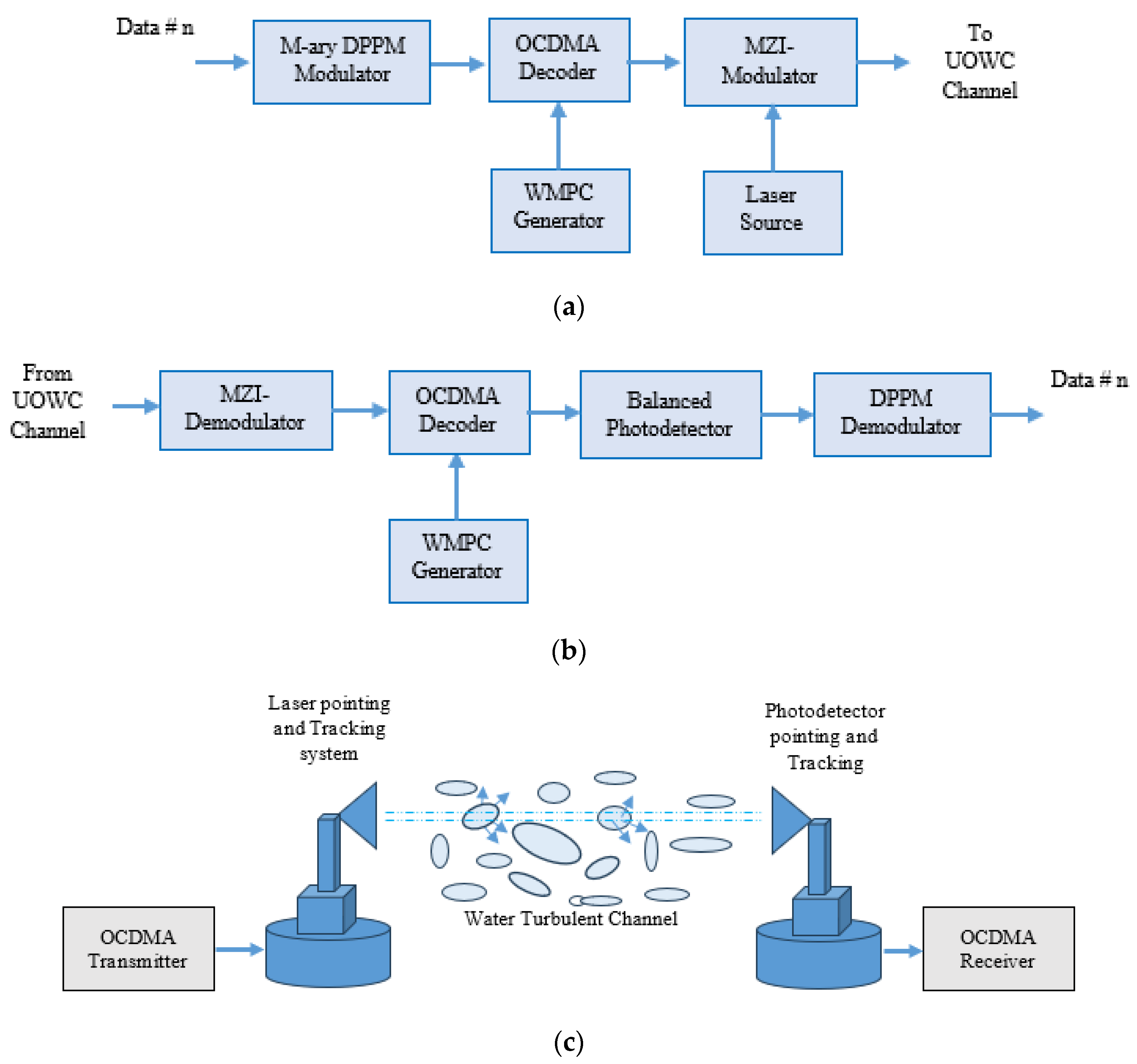
3. Proposed System Model

Figure 2 presents the proposed UOWC/CDMA system. Figure 2a shows the OCDMA transmitter, which consists of an OCDMA encoder for encoding and spreading the data using the WMPC spreading sequence. The encoded data are modulated using the M-ary DPPM to control the channel dispersion by controlling the pulse width of the DPPM signal and consequently reducing the inter-symbol interference (ISI). A Mach–Zehnder interferometer (MZI) modulator is used to modulate the laser light intensity using the encoded modulated signal. The received optical signal is first demodulated by the MZI demodulator, then DPPM demodulated and decoded using the WMPC decoder, and finally, the balanced detector is used to convert the optical data to electrical data and eliminate noise.
Furthermore, the use of DPPM gives the system an advantage in the case of multimedia applications. In this case, we can control and optimize the BER performance as in the case of [40].
The LOS-UOWC channel in Figure 2c can be modeled using the equation below, as in the case of [3,43,44,45,46]. The level of optical power received P r   depends on the optical power transmitted by the laser diode P t   ; the transmitter and receiver optical efficiencies η t and η r , respectively; the angle of the trajectory perpendicular to the transmitter–receiver planes θ ; the aperture area of photodetector A r ; and the divergence angle of the laser beam θ d [13]. α λ is the attenuation coefficient of the wireless underwater channel and is discussed in detail in Section 4.
P r = P t   η t η r   e x p α λ d cos θ A r cos θ 2 π d 2 1 cos θ d
The scintillation phenomenon is important and must be considered in the UOWC channel modeling. This phenomenon characterizes the chaotic change in the water flow velocity and pressure, and this turbulence affects the water characteristics when laser light beams propagate underwater. This results in fluctuations in the optical power and degrades the system performance owing to variations in the refractive index of water [22,46,47,48,49,50,51]. Various UOWC system models are used to represent the effect of turbulence on the system performance; however, for weak turbulence, the gamma–gamma model is suitable. The probability density function of the irradiance I r investigates the effect of turbulence on system performance, and various UOWC channel models can be expressed as in [11] as follows:
P I r = I r ψ 1   e x p I r ψ · ψ ψ Γ ψ
where ψ is a parameter function that represents the effect of the scintillation index δ p 2 as in (3), and Γ ψ is the gamma function of ψ .
ψ = 1 δ p 2
The scintillation index δ p 2 can be expressed as follows:
δ p 2 = a b + a + b
where a and b are parameters defined as
a = e x p 0.49 σ I r 2 1 + 0.18 L 2 + 0.56 σ I r 12 / 5 7 / 6 1
b = e x p 0.51 σ I r 2 1 + 0.9 L 2 + 0.62 σ I r 12 / 5 5 / 6 1 + 0.62 σ I r 12 / 5 5 / 6 1
where σ I r is the normalized intensity variance, and L = k D 2 / 4 d , where d is the transmission distance, D is the receiver photodetector aperture diameter, and k = 2 π λ is the wave number.
There are two main problems in the case of optical propagation underwater: the high absorption of the optical signal in the water medium and scattering due to the particles in the seawater. In the visible spectrum of light, especially in the 450–470 nm range blue–green region, seawater has a lower absorption and consequently lower attenuation, and the lowest value of this attenuation occurs at 460 nm in clear ocean water. Furthermore, in coastal waters, this wavelength range shifts to 530–550 nm [47,48]. In the low scattering regime, we can describe the light propagation in water using the spectral attenuation coefficient α ( λ ) , which is the sum of the scattering and absorption coefficients S ( λ ) and A ( λ ) , respectively. The involvement of water molecules, dissolved colored organic content, and particulate algal/sediment matter are the main factors that determine the absorption and scattering coefficients in m 1 [50,51,52]. In addition to the effect of wavelength on the absorption, the type of particles and level of turbidity significantly affect the absorption and scattering coefficients. Two types of particles are important in seawater: phytoplankton and organic particles, both of which affect the light properties. The first type strongly absorbs the blue and red regions of light. In turbid water, the scattering of photons results in a decrease in the received optical power, and several photons are received with delays, causing ISI.
Every type of water is characterized by a value of chlorophyll concentration C , which also affects the values of the absorption and scattering coefficients and can be expressed simply as shown in (7) and (8), respectively [29,30,31,32,33,47,52]:
A λ = A ω ( λ ) + 0.06 A C ( λ ) C 0.65 1 + 0.2 e x p 0.014 ( λ 440
S λ = 0.30 550 λ C 0.62
where A ω ( λ ) is the absorption coefficient for pure water, A C ( λ ) is a statistical dimensionless specific absorption coefficient for chlorophyll, and C is the chlorophyll concentration of 0.03, 0.1, 0.38, and 3 mg/m3 for pure seawater, clear ocean water, coastal ocean water, and turbid harbor water, respectively.
In general, the sum of (7) and (8) provides the cumulative attenuation coefficient as follows:
α ( λ ) = A ( λ ) + S λ
On substituting (7) and (8) into (9), the attenuation coefficient can be expressed as follows:
α λ = A ω ( λ ) + 0.06 A C ( λ ) C 0.65 1 + 0.2 e x p 0.014 ( λ 440 + 0.30 550 λ C 0.62
This coefficient is the main parameter affecting the transmission distance for the UOWC channel, and the propagation loss factor is written by Beer as [51,52]
L P λ ,   d = B × e x p α λ × d
where B is a constant. As the transmission distance increases, the scattering of photons increases, and the diffusion length plays a significant role for the non-LOS photons, as shown in Figure 3. In this case, Beer’s equation can be rewritten as
L P λ ,   d = B 1 × e x p α 1 λ × d + B 2 × e x p α 2 λ × d  
where the first term represents the attenuation loss length, which is less than the diffusion length; the second term represents the attenuation loss length, which is greater than the diffusion length; and B 1 and B 2 are constants equal to 0.25 and 0.006 for pure water and 0.15 and 0.198 for clear ocean water at 460 nm, respectively. The absorption, scattering, and attenuation coefficients are presented in Figure 4 as a function of the wavelength from 200–700 nm in pure seawater. The figure shows that the scattering coefficient is lower in the range of 400–600 nm around the center wavelength of 500 nm, and the absorption coefficient appears as a constant during this range and varies from 0.105 at 400 nm to 0.08 at 600 nm. Before 350 nm and after 600 nm, the scattering and attenuation are high, which reduces the transmission distance to less than 1 m.

4. WMPC Sequence Generation

The WMPC is a superior code sequence generated from the existing modified prime code (MPC) presented in [35]. The WMPC is called a weighted MPC because it has a code weight equal to twice the code weight of the MPC sequence minus one with the same code length and better correlation characteristics. Furthermore, the MPC was generated according to a prime number P , which represents the code weight (i.e., the number of logic ones “HIGH” in the code sequence) and the number of code words, where each word consists of P time chips; one of these chips is logic HIGH and the remainder ( P 1 ) chips are logic zero “LOW”, where P   3 ,   5 ,   7 ,   11 ,   13 ,   , e t c . . The code length equals P 2 , which represents the number of time chips that encode one data bit; the number of code sequences generated is P 2 P as in [35,36,37,38,39,40,41]. In the WMPC, we create an XOR between each pair of code words to generate a new code word containing two one’s logic HIGH; however, the middle code word remains the same and the resulting code weight becomes 2 P 1 . The code length also remains the same as in the case of the MPC; however, the peak value of the autocorrelation function of any WMPC sequence equals 2 P 1 instead of P in the MPC, and the number of available code sequences equals 2( P 2 P ) as in [40]. Table 2 presents the MPC and related WMPC sequences for P = 5 . Equation (13) presents the correlation coefficient C m n between the two code sequences m   a n d   n .
On assuming the chip time T C and data bit time duration as T b , we can express T b as a function of T C , as shown in (14).
R S m n = 2 P 1                                                                                                                                           i f   m = n 0             i f   m   n   a n d   t h e   t w o   s e q u e n c e s   s h a r e   t h e   s a m e   g r o u p 1           i f   m   n   a n d   t h e   t w o   s e q u e n c e s   f r o m   d i f f e r e n t   g r o u p s
T b = P 2 T C
When the M-ary DPPM is used with the WMPC, each differential pulse from the M differential pulses takes its own code sequence, and all sequences are orthogonal to prevent interference from multiple users. At this point, Equation (14) can be rewritten as
T b = M P 2 T C
This means that the M-DPPM/WMPC hybrid scheme is more power-efficient than the WMPC and more efficient than the M-DPPM. In addition, there are three parameters that control the user bit rate and consequently control the network throughput M , P , and T C , where T C depends on the type of laser diode used and the network security owing to the presence of the WMPC.
Figure 5 presents the auto-correlation coefficient of the WMPC sequence S 11 . This result shows that, at 25 T C , which equals the bit time, the auto-correlation coefficient peaks and is equal to nine, which is equivalent to 2 P 1 . Figure 6 presents the cross-correlation coefficient between the two code sequences S 10   a n d   S 41 from the two different groups, and the result shows that at 25 T C , the correlation coefficient is at a minimum and equal to one, which satisfies the correlation definition in (13).

5. Performance Analysis

Before performing the BER analysis, we illustrate and define the signal-to-noise ratio ( S N R ) parameters in Table 3. The average S N R can be calculated as shown in (16) below, and the photocurrent at the photodetector output I P = R · P r is the PIN responsivity multiplied by the optical power received. Furthermore, to investigate the effect of irradiance, the instantaneous SNR defined in (17) must be considered in the BER performance analysis.
S N R = I P 2 G 2 2 q I P + I D G 2 F G B e + 4 K B T B e / R L
S N R i = S N R   · I r
Before calculating the BER performance, we define the values of the transmission parameters, such as the optical power transmitted, transmission efficiencies, operating wavelength range, receiver aperture area, and coding parameters, as listed in Table 4. The chip time was adjusted to 2.6 ps, and the BER performance was calculated several times for prime numbers ranging from 11 to 61.
In the BER performance results, we compared different types of water as transmission media according to their chlorophyll concentration, and the OOK modulation scheme was used as a reference to compare the results with those of the proposed M-DPPM scheme. Therefore, the probability of error for both the modulation schemes is illustrated in (18) and (19), as listed below, where γ t h is the receiver threshold value that is adjusted using a decision circuit after the correlator, and M is the system multiplicity according to the M-DPPM modulation scheme [30,31,32,33,34].
1 2 e r f c S N R i 2 2
  1 M 1 2 e r f c 1 γ t h × M × S N R i 8 + M 1 2 e r f c γ t h × M × S N R i 8
When the WMPC is considered, the BER performance is the result of the probability of error of the M-DPPM scheme multiplied by the probability of error owing to the proposed WMPC. For this analysis, we must consider the effect of multiple-user interference when chips from other users interfere with the desired chip owing to multiple access. Table 5 lists the WMPC BER performance parameters used in (21) [35,36,37,38,39,40,41].
The total BER performance of the proposed M-DPPM/WMPC scheme can be written as [35,36,37,38,39,40,41].
B E R = B E R M D P P M · P E
where P E given as
P E w 1 = 2 P N u N u w 1 1 M w 1 . 1 1 M N u w 1 . w 0 = 0 min w 1 2 P ,     N u w 1 N u w 1 w 0 1 M 1 w 0 1 1 M 1 N u w 0 w 1 + 0.5 w 1 = 2 P 1 N u + 2 P 1 2 N u w 1 1 M w 1 1 1 M N u w 1 N u w 1 w 1 2 P + 1 1 ( M 1 ) w 1 2 P + 1

6. EVM Analysis

The EVM is a new metric used to measure the quality of an optical signal in terms of the BER performance and optical SNR (OSNR). To evaluate the EVM, the received error vector and ideal transmitted vector must be defined, and the root mean square of the difference between these two vectors is calculated [53,54]. For the M-ary DPPM and WMPC modulation and coding schemes, we can express EVM as
E V M = 1 1 M 0.5 l o g 2 M e r f c ( 3 2 M 1 E V M 2 )
and the percentage of the EVM can be expressed as
E V M % = B E R m a x B E R B E R 100 %

7. Results and Discussion

In this section, we focus on the BER performance versus the transmission distance and number of active users and investigate the effect of the type of water, type of modulation scheme, operating wavelength, multiplicity parameter, aperture area, and WMPC parameters. Furthermore, EVM and OSNR are compared in these results for their different coding schemes. Figure 7 presents the BER performance versus the transmission distance for the OOK-OCDMA and 2-DPPM-OCDMA systems for different types of water at receiver apertures of 400 nm and a 0.01 m2 receiver aperture. From this figure, we can observe that the 2-DPPM modulation scheme almost outperforms the OOK modulation scheme, and the system can communicate over a range of 17 m, 15 m, and 7.5 m for the type-1 pure seawater with C = 0.03, type-2 ocean clear water with C = 0.38, and type-3 unclear ocean water at C = 3, respectively, at 10−9 BER. In the case of type 3, the transmission distance was incomparable to those of the other two types owing to the large amount of attenuation that occurred. The effect of the operating wavelength is presented in Figure 8 in the transmission distance for OOK-OCDMA and 2-DPPM-OCDMA in the case of type-1 pure seawater with C = 0.03 at a 0.01 m2 receiver aperture area. In this figure, we observe that the best communication distance is 460 nm in the blue–green region, which outperforms the results at 400 nm and 600 nm. At a 10−9 BER performance, when the operating wavelength is 460 nm, the system can communicate over a range of 18 m compared to the 5.5 m transmission distance at 600 nm. The effect of the receiver aperture area is presented in Figure 9, which shows the BER performance versus transmission distance for the OOK-OCMDA and 2-DPPM-OCDMA systems at 460 nm in pure seawater. When the receiver aperture area increases, the receiver field of view increases, and more optical power can be received, which allows the system to communicate over a longer transmission distance. In Figure 9, when the receiver aperture increased to 0.05 m2, the system could communicate over 22 m compared to 18 m for a 0.01 m2 receiver aperture area at 10−9 BER performance. From the above results, we can conclude that the M-DPPM is a better modulation scheme than the OOK. In the following results regarding how we can increase the transmission distance underwater, the effect of the coding and system multiplicity must be taken into consideration. Figure 10 presents the 2-DPPM/WMPC-OCDMA system BER performance versus the transmission distance for pure seawater, with C = 0.03, at 460 nm, receiver aperture area of 0.05 m2, and different values of the WMPC prime number P. The variation in the prime number P varies the code sequence length and code weight, and the increase in P increases the code weight and consequently increases the optical power received. This also enhances the BER performance and increases the transmission distance.
As shown in Figure 10, when the prime number P increases, the transmission distance increases until a certain value is reached. Above this value, the increase in P did not change the transmission distance because the system’s multiple-access interference degrades the OSNR. In these results, P varied from 11 to 59, and the transmission distance varied from 45 m to 155 m. From P = 53 to 59, the change in the transmission distance was less at approximately 5 m, and it is clear from the figure when P increases above 43 at 53, 57, and 59. For more clearance, we can see that above 53, the increase in the transmission distance is slightly above 57, and the transmission distance is approximately the same. This is because when P increases, the multiple-user interference increases and reduces the OSNR, and there is no effort to increase the code parameter P.
Figure 11 shows the BER performance versus the received optical power for the M-DPPM/WMPC-OCDMA system for pure seawater with C = 0.03, at 460 nm, receiver aperture area of 0.05 m2, WMPC prime number P = 53, transmission distance 800 m, and different values of system multiplicity M. The results show that when the received optical power increases, the BER performance improves. Also, this figure shows the BER performance enhanced with the system multiplicity increase.
Figure 12 presents the BER performance versus the transmission distance for the M-DPPM/WMPC-OCDMA system for pure seawater with C = 0.03, at 460 nm, receiver aperture area of 0.05 m2, WMPC prime number P = 53, and different values of system multiplicity M. According to Equation (19) in Table 5, when the system multiplicity increases, the SNR increases, and the BER performance decreases, which increases the link transmission distance. However, when M increases to a certain value, the transmission distance increases at a low rate, and above this value, the transmission does not change as M increases. Figure 12 shows that when M increases from 2 to 512, the transmission distance increases from 155 m to 930 m at a BER of 10−9. Above M = 512, the transmission distance does not change owing to degradation in the OSNR.
Based on the above results, we obtained the optimum system parameters for calculating the network capacity and bit rate per user. Figure 13 illustrates the BER performance versus the number of active users N for the 256-DPPM/WMPC system, while considering all the optimum parameters achieved above at different values of the coding parameter P. The results showed that when P was increased from 23 to 59, the number of active users increased from 360 to 1310. Above P = 59, the multiple-access interference increases, and the number of active users remains the same at a BER performance of 10−9. From the results obtained without any interference, we find the code sequence chip time duration T c = 2.6 ps, and the optimal value of P = 53, and thus, the bit time duration can be calculated as
T b = P 2 T c = 2809 × 2.6   p s = 7.3   n s
Furthermore, the bit rate R b = 1 T b = 137   M b p s , and the network throughput equals 137   Mbps × 1310   user = 180   Gbps user .
The EVM% versus the system OSNR for different types of modulation schemes is presented in Figure 14. This figure illustrates that the proposed 256-DPPM/WMPC scheme outperformed the other modulation schemes for any EVM%. Moreover, when the proposed scheme was considered, the EVM% was the lowest at any OSNR. Furthermore, at 30 dB OSNR, the EVM% was 17%, 5%, and 2% for the 64-DPPM, 256-DPPM, and 265-DPPM/WMPC modulation schemes, respectively. This was due to the sufficient optical signal received at the receiver and the high efficiency of the proposed hybrid modulation/coding scheme. Table 6 compares the published and proposed techniques for underwater optical and wireless communication systems. This comparison includes the BER performance, transmission distance, number of active users, bit rate, and network throughput. From this comparison, we observe that the proposed modulation/coding scheme outperforms other published methods in terms of transmission distance and network throughput.

8. Conclusions

In this study, a coherent 265-DPPM/WMPC-OCDMA system was designed for underwater optical wireless communication. The design of the OCDMA transceiver architecture is based on hybrid M-DPPM modulation using the WMPC sequence scheme. The WMPC design methodology and its correlation characteristics were introduced. A mathematical model of the channel absorption, scattering, and attenuation was studied as a function of the operating wavelength and chlorophyll concentration coefficient. Furthermore, the effect of the concentration coefficient on the signal attenuation and transmission distance is presented. Variations in the operating wavelength and receiver aperture area were also investigated. The system multiplicity variation and coding parameters were considered in the BER analysis to enhance the transmission distance between the transmitter and receiver. Moreover, the results proved that the proposed 256-DPPM/WMPC system can accommodate 1310 users communicating over 930 m under pure seawater without repeaters at a data rate of 137 Mbps and 10−9 BER at 2% EVM%.

Author Contributions

Conceptualization, M.A.M.I.; Methodology, M.A.M.I.; Software, M.A.M.I.; Validation, K.S.; Formal analysis, M.A.M.I.; Investigation, K.S.; Resources, K.S.; Data curation, M.A.M.I.; Writing—original draft, M.A.M.I.; Visualization, M.A.M.I. and K.S.; Writing—review; M.A.M.I. and K.S. All authors have read and agreed to the published version of the manuscript.

Funding

This research received no external funding.

Data Availability Statement

The data supporting the findings of this study are available from the corresponding author upon reasonable request.

Conflicts of Interest

The authors declare no conflict of interest.

References

  1. Álvarez-Roa, C.; Álvarez-Roa, M.; Raddo, T.R.; Jurado-Navas, A.; Castillo-Vázquez, M. Cooperative Terrestrial–Underwater FSO System: Design and Performance Analysis. Photonics 2024, 11, 58. [Google Scholar] [CrossRef]
  2. Shen, C.; Guo, Y.; Oubei, H.M.; Ng, T.K.; Liu, G.; Park, K.-H.; Ho, K.-T.; Alouini, M.-S.; Ooi, B.S. 20-meter underwater wireless optical communication link with 1.5 Gbps data rate. Opt. Expr. 2016, 24, 25502–25509. [Google Scholar] [CrossRef] [PubMed]
  3. Lu, C.; Wang, J.; Li, S.; Xu, Z. 60 m/2.5 Gbps underwater optical wireless communication with NRZ-OOK modulation and digital nonlinear equalization. In Proceedings of the Conference on Lasers and Electro-Optics (CLEO), San Jose, CA, USA, 5–10 May 2019; IEEE: Piscataway, NJ, USA, 2019; pp. 1–2. [Google Scholar] [CrossRef]
  4. Du, J.; Wang, Y.; Fei, C.; Chen, R.; Zhang, G.; Hong, X.; He, S. Experimental demonstration of 50-m/5-Gbps underwater optical wireless communication with low-complexity chaotic encryption. Opt. Expr. 2021, 29, 783–796. [Google Scholar] [CrossRef] [PubMed]
  5. Hassan, W.H.W.; Sabril, M.S.; Jasman, F.; Idrus, S.M. Experimental study of light wave propagation for underwater optical wireless communication. J. Commun. 2022, 17, 23–29. [Google Scholar] [CrossRef]
  6. Baykal, Y.; Ata, Y.; Gökçe, M.C. Underwater turbulence, its effects on optical wireless communication and imaging: A review. Opt. Laser Technol. 2022, 156, 108624. [Google Scholar] [CrossRef]
  7. Kou, L.; Zhang, J.; Zhang, P.; Yang, Y.; He, F. Composite channel modeling for underwater optical wireless communication and analysis of multiple scattering characteristics. Opt. Express 2023, 31, 11320–11334. [Google Scholar] [CrossRef] [PubMed]
  8. Liu, X.; Yi, S.; Zhou, X.; Fang, Z.; Qiu, Z.-J.; Hu, L.; Cong, C.; Zheng, L.; Liu, R.; Tian, P. 345 m underwater optical wireless communication with 270 Gbps data rate based on a green laser diode with NRZ-OOK modulation. Opt. Express 2017, 25, 27937–27947. [Google Scholar] [CrossRef] [PubMed]
  9. Liu, W.; Zhang, L.; Huang, N.; Xu, Z. Wide dynamic range signal detection for underwater optical wireless communication using a PMT detector. Opt. Express 2023, 31, 25267–25279. [Google Scholar] [CrossRef]
  10. Wang, J.; Lu, C.; Li, S.; Xu, Z. 100 m/500 Mbps underwater optical wireless communication using an NRZ-OOK modulated 520 nm laser diode. Opt. Express 2019, 27, 12171–12181. [Google Scholar] [CrossRef]
  11. Mohammed Salim, O.N.; Adnan, S.A.; Mutlag, A.H. Underwater optical wireless communication system performance improvement using convolutional neural networks. AIP Adv. 2023, 13, 045302. [Google Scholar] [CrossRef]
  12. Zhang, W.; Wang, L.; Wu, X.; Fei, L.; Peng, H.; Wen, K.; Zhao, Y. Performance Evaluation of Maximum Ratio Combining Diversity Technology and Traditional System Based on Comprehensive Noise Analysis in Underwater Wireless Optical Communication. Photonics 2023, 10, 1388. [Google Scholar] [CrossRef]
  13. Hu, S.; Mi, L.; Zhou, T.; Chen, W. 3588 attenuation lengths and 332 bits/photon underwater optical wireless communication based on photon-counting receiver with 256-PPM. Opt. Express 2018, 26, 21685–21699. [Google Scholar] [CrossRef] [PubMed]
  14. Shen, T.; Guo, J.; Liang, H.; Li, Y.; Li, K.; Dai, Y.; Ai, Y. Research on a Blue–Green LED Communication System Based on an Underwater Mobile Robot. Photonics 2023, 10, 1238. [Google Scholar] [CrossRef]
  15. Chen, Y.; Kong, M.; Ali, T.; Wang, J.; Sarwar, R.; Han, J.; Guo, C.; Sun, B.; Deng, N.; Xu, J. 26 m/55 Gbps air-water optical wireless communication based on an OFDM-modulated 520-nm laser diode. Opt. Express 2017, 25, 14760–14765. [Google Scholar] [CrossRef]
  16. Chen, D.; Wang, J.; Li, S.; Xu, Z. Effects of air bubbles on underwater optical wireless communication [Invited]. Chin. Opt. Lett. 2019, 17, 100008. [Google Scholar] [CrossRef]
  17. Rong, Y.; Nordholm, S.; Duncan, A. On the capacity of underwater optical wireless communication systems. In Proceedings of the 2021 Fifth Underwater Communications and Networking Conference (UComms), Lerici, Italy, 31 August–2 September 2021; IEEE: Piscataway, NJ, USA, 2021; pp. 1–4. [Google Scholar]
  18. Geldard, C.T.; Guler, E.; Hamilton, A.; Popoola, W.O. An empirical comparison of modulation schemes in turbulent underwater optical wireless communications. J. Light. Technol. 2022, 40, 2000–2007. [Google Scholar] [CrossRef]
  19. Huang, X.; Yang, F.; Song, J. Hybrid LD and LED-based underwater optical communication: State-of-the-art, opportunities, challenges, and trends. Chin. Opt. Lett. 2019, 17, 100002. [Google Scholar] [CrossRef]
  20. Gabriel, C.; Khalighi, M.-A.; Bourennane, S.; Léon, P.; Rigaud, V. Monte-Carlo-based channel characterization for underwater optical communication systems. J. Opt. Commun. Netw. 2013, 5, 1–12. [Google Scholar] [CrossRef]
  21. Saeed, N.; Celik, A.; Al-Naffouri, T.Y.; Alouini, M.S. Underwater optical wireless communications, networking, and localization: A survey. Ad Hoc Netw. 2019, 94, 101935. [Google Scholar] [CrossRef]
  22. Han, S.; Noh, Y.; Liang, R.; Chen, R.; Cheng, Y.-J.; Gerla, M. Evaluation of underwater optical-acoustic hybrid network. China Commun. 2014, 11, 49–59. [Google Scholar] [CrossRef]
  23. Kaushal, H.; Kaddoum, G. Underwater optical wireless communication. IEEE Access 2016, 4, 1518–1547. [Google Scholar] [CrossRef]
  24. Farr, N.; Bowen, A.; Ware, J.; Pontbriand, C.; Tivey, M. An integrated, underwater optical/acoustic communications system. In Proceedings of the OCEANS’10 IEEE SYDNEY, Sydney, NSW, Australia, 24–27 May 2010; IEEE: Piscataway, NJ, USA, 2010; pp. 1–6. [Google Scholar]
  25. Willner, A.E.; Zhao, Z.; Ren, Y.; Li, L.; Xie, G.; Song, H.; Liu, C.; Zhang, R.; Bao, C.; Pang, K. Underwater optical communications using orbital angular momentum-based spatial division multiplexing. Opt. Commun. 2018, 408, 21–25. [Google Scholar] [CrossRef]
  26. Al-Zhrani, S.; Bedaiwi, N.M.; El-Ramli, I.F.; Barasheed, A.Z.; Abduldaiem, A.; Al-Hadeethi, Y.; Umar, A. Underwater optical communications: A brief overview and recent developments. Eng. Sci. 2021, 16, 146–186. [Google Scholar] [CrossRef]
  27. Lu, H.; Jiang, M.; Cheng, J. Deep learning aided robust joint channel classification, channel estimation, and signal detection for underwater optical communication. IEEE Trans. Commun. 2020, 69, 2290–2303. [Google Scholar] [CrossRef]
  28. Zhu, S.; Chen, X.; Liu, X.; Zhang, G.; Tian, P. Recent progress in and perspectives of underwater wireless optical communication. Prog. Quantum Electron. 2020, 73, 100274. [Google Scholar] [CrossRef]
  29. Zhao, Y.; Wang, A.; Zhu, L.; Lv, W.; Xu, J.; Li, S.; Wang, J. Performance evaluation of underwater optical communications using spatial modes subjected to bubbles and obstructions. Opt. Lett. 2017, 42, 4699–4702. [Google Scholar] [CrossRef] [PubMed]
  30. Zhou, H.; Zhang, M.; Wang, X.; Ren, X. Design and implementation of more than 50m real-time underwater wireless optical communication system. J. Light. Technol. 2022, 40, 3654–3668. [Google Scholar] [CrossRef]
  31. Nguyen, C.T.; Nguyen, M.T.; Mai, V.V. Underwater optical wireless communication-based IoUT networks: MAC performance analysis and improvement. Opt. Switch. Netw. 2020, 37, 100570. [Google Scholar] [CrossRef]
  32. Ismail, M.A.M.; Saleh, K. Performance analysis toward 880 m/4.255 Gbps underwater optical wireless communication CDMA network based on hybrid M-ary differential pulse position modulation and double length modified prime code. Opt. Quantum Electron. 2024, 56, 668. [Google Scholar] [CrossRef]
  33. Xu, J. Underwater wireless optical communication: Why, what, and how? Chin. Opt. Lett. 2019, 17, 100007. [Google Scholar] [CrossRef]
  34. Spagnolo, G.S.; Cozzella, L.; Leccese, F. Underwater optical wireless communications: Overview. Sensors 2020, 20, 2261. [Google Scholar] [CrossRef] [PubMed]
  35. Morsy, M.A.; Alsayyar, A.S. Performance analysis of OCDMA wireless communication system based on double length modified prime code for security improvement. IET Commun. 2020, 14, 1139–1146. [Google Scholar] [CrossRef]
  36. Morsy, M.A.; Alsayyari, A.S. Performance analysis of coherent BPSK-OCDMA wireless communication system. Wirel. Netw. 2020, 26, 4491–4505. [Google Scholar] [CrossRef]
  37. Morsy, M.A. Analysis and design of weighted MPC in incoherent synchronous OCDMA network. Opt. Quantum Electron. 2018, 50, 387. [Google Scholar] [CrossRef]
  38. Morsy, M.A.; Alsayyari, A.S. Multi-rate OCDMA system BER performance evaluations for different ML-code sequences. Opt. Quantum Electron. 2019, 51, 198. [Google Scholar] [CrossRef]
  39. Morsy, M.A.; Alsayyari, A.S. Performance analysis of incoherent PPM-OCDMA networks based on optimised modified prime code for multimedia applications. IET Commun. 2020, 14, 4014–4021. [Google Scholar] [CrossRef]
  40. Morsy, M.A. Coherent OCDMA network based on a new BER performance equalization technique for multimedia applications. Opt. Quantum Electron. 2023, 55, 167. [Google Scholar] [CrossRef]
  41. Ismail, M.A.M.; Alsayyari, A.; Galal, O.H. Performance analysis of optical code division multiple access networks for multimedia applications using multilength weighted modified prime codes. Opt. Eng. 2019, 58, 035101. [Google Scholar] [CrossRef]
  42. Chen, L.-K.; Shao, Y.; Di, Y. Underwater and water-air optical wireless communication. J. Light. Technol. 2021, 40, 1440–1452. [Google Scholar] [CrossRef]
  43. Adnan, S.A.; Hassan, H.A.; Alchalaby, A.; Kadhim, A.C. Experimental study of underwater wireless optical communication from clean water to turbid harbor under various conditions. Int. J. Des. Nat. Ecodynamics 2021, 16, 219–226. [Google Scholar] [CrossRef]
  44. Kumari, M. Performance analysis of high speed hybrid PON-VLC for long-reach land-to-underwater applications. Wirel. Netw. 2023, 29, 1721–1735. [Google Scholar] [CrossRef]
  45. Sabhapathy, U.; Wilson, L.A. Implementation of underground water for wireless optical communication system using CDMA. Int. Innov. Res. J. Eng. Technol. 2021, 6, 10–20. [Google Scholar] [CrossRef]
  46. Joseph, D.; Karthikeyan, A.; Kuppusamy, P.G.; Prabhu, V. Investigations on hybrid wavelength-mode-orthogonal frequency-division multiplexing scheme based free space optical transmission system under varying atmospheric conditions. Opt. Quantum Electron. 2022, 54, 64. [Google Scholar] [CrossRef]
  47. Sabbagh, A.G.; Miandehi, F.Z. Performance analysis of unequal-mark-power optical CDMA systems. IEEE Trans. Commun. 2020, 68, 3696–3705. [Google Scholar] [CrossRef]
  48. Zedini, E.; Kammoun, A.; Soury, H.; Hamdi, M.; Alouini, M.-S. Performance analysis of dual-hop underwater wireless optical communication systems over mixture exponential-generalized gamma turbulence channels. IEEE Trans. Commun. 2020, 68, 5718–5731. [Google Scholar] [CrossRef]
  49. Al Hammadi, M.M.; Islam, M.J. Performance evaluation of underwater wireless optical CDMA system for different water types. Photonic Netw. Commun. 2020, 39, 246–254. [Google Scholar] [CrossRef]
  50. Kandouci, C. Investigation of Jervol water types properties effects on underwater optical wireless OCDMA system performances for different modulation techniques. Opt. Quantum Electron. 2022, 54, 3. [Google Scholar] [CrossRef]
  51. Kandouci, C. Performances enhancement of underwater wireless optical communications (UWOC) using pulse position modulation. J. Opt. Commun. 2022, 43, 289–294. [Google Scholar] [CrossRef]
  52. Shiu, D.S.; Kahn, J.M. Differential pulse-position modulation for power-efficient optical communication. IEEE Trans. Commun. 1999, 47, 1201–1210. [Google Scholar] [CrossRef]
  53. Morsy, M.A.; Aly, M.H. A new hybrid prime code for OCDMA network multimedia applications. Electronics 2021, 10, 2705. [Google Scholar] [CrossRef]
  54. Morsy, M.A.; Hadeel, S.A.R.; Al-Obaidan, H.M. Performance of Passive OCDMA Networks for Different Encoder/Decoder Delay Lines. Int. J. Opt. Appl. 2013, 3, 19–26. [Google Scholar]
Figure 1. Ship–submarine communication underwater [34].
Photonics 11 00368 g001
Figure 2. Proposed OCDMA system for user #n out of N active users: (a) Transmitter, (b) Receiver, and (c) LOS-UOWC channel model.
Photonics 11 00368 g002
Figure 3. Diffuse LOS and point-to-point LOS configurations of light underwater between two submarines [34].
Photonics 11 00368 g003
Figure 4. Attenuation, absorption, and scattering coefficients for pure water versus wavelength when C = 0.03 .
Photonics 11 00368 g004
Figure 5. Auto-correlation coefficient of the WMPC sequence S 11 .
Photonics 11 00368 g005
Figure 6. Cross-correlation coefficient between the WMPC sequences S 10   a n d   S 41 .
Photonics 11 00368 g006
Figure 7. BER performance versus the transmission distance of OOK-OCDMA and 2-DPPM-OCDMA systems for different types of water at 400 nm and receiver aperture of 0.01 m2.
Photonics 11 00368 g007
Figure 8. BER performance versus the transmission distance for OOK-OCDMA and 2-DPPM-OCDMA systems for pure seawater, with C = 0.03 at a receiver aperture of 0.01 m2 and different wavelengths.
Photonics 11 00368 g008
Figure 9. BER performance versus the transmission distance of OOK-OCDMA and 2-DPPM-OCDMA systems for pure seawater, with C = 0.03, at 460 nm and different receiver aperture areas.
Photonics 11 00368 g009
Figure 10. BER performance versus the transmission distance of 2-DPPM/WMPC-OCDMA system for pure seawater with C = 0.03, at 460 nm, receiver aperture area of 0.05 m2, and different values of the WMPC prime number P.
Photonics 11 00368 g010
Figure 11. BER performance versus the received power of the M-DPPM/WMPC-OCDMA system for pure seawater, with C = 0.03, at 460 nm, receiver aperture area of 0.05 m2, WMPC prime number P = 53, d = 800   m , and different values of system multiplicity M.
Photonics 11 00368 g011
Figure 12. BER performance versus the transmission distance of the M-DPPM/WMPC-OCDMA system for pure seawater, with C = 0.03, at 460 nm, receiver aperture area of 0.05 m2, WMPC prime number P = 53, and different values of system multiplicity M.
Photonics 11 00368 g012
Figure 13. BER performance versus the number of active users N for the 256-DPPM/WMPC-OCDMA system for pure seawater, with C = 0.03, at 460 nm, receiver aperture area of 0.05 m2, and different values of the WMPC prime number P.
Photonics 11 00368 g013
Figure 14. EVM% versus OSNR of underwater OCDMA system for different modulation schemes.
Photonics 11 00368 g014
Table 1. Literature review comparison of results for developed underwater wireless channels.
Ref.ParametersOpticalRF WavesAcoustic Waves
[14]Attenuation0.39 dB/m (ocean)–11 dB/m (turbid)--
Speed (m/s)2.26 × 108
Data rate~Gbps
LatencyLow
Distance10–100 m
[13]Attenuation-Frequency band and conductivity dependent
(3.5–5) dB/m
-
Speed (m/s)2.26 × 108
Data rate~Mbps
LatencyModerate
DistanceUp to 10 m
[12]Attenuation Distance- and frequency-dependent
(0.1–4) dB/km
Speed (m/s) 1500
Data rate ~Kbps
Latency High
Distance Up to Kms
[8]Bandwidth10–150 MHzAbout MHzDistance dependent
1000 km and 1 kHz
1–10 km and 10 kHz
Less than 100 m and 100 kHz
Frequency band1012–1015 Hz30–300 Hz for direct underwater communication system or MHz for buoyant communication system10–15 kHz
Transmission powerFew WattsFew mW to hundreds of WattsTens of Watts
Antenna size0.1 m0.5 m0.1 m
Efficiency30,000 bits/J-100 bits/J
Performance parametersAbsorption and organic matterConductivity and permittivityTemperature and pressure
[29,30,31]Code length121–289 Chip121–289 Chip121–289 Chip
BER performanceLess than 10−20Less than 10−15Less than 10−10
Number of users110–18090–10030–50
Throughput performance1 Tbps*user10 Gbps*userLess than Mbps*user
[43,44,45]Number of orthogonal frequenciesLess than 32Less than 16-
Number of users20–321–16
BER performanceLess than 10−12Less than 10−9
Throughput performanceApproximately 100 Gbps*userApproximately 1 Gbps*user
Table 2. WMPC sequence generation for P = 5 .
Group
x
i
0 1 2 3 4
SequenceMPC PartWMPC Part
10 1 2 3 4S1,010000–01000–00100–00010–0000110010–01001–00100–00101–01010 A
01001–10010–00100–01010–00101 B
4 0 1 2 3S1,100001–10000–01000–00100–0001000101–10010–01000–01010–10100 A
10010–00101–01000–10100–01010 B
3 4 0 1 2S1,200010–00001–10000–01000–0010001010–00101–10000–10100–01001 A
00101–01010–10000–01001–10100 B
2 3 4 0 1S1,300100–00010–00001–10000–0100010100–01010–00001–01001–10010 A
01010–10100–00001–10010–01001 B
1 2 3 4 0S1,401000–00100–00010–00001–1000001001–10100–00010–10010–00101 A
10100–01001–00010–00101–10010 B
.
.
.
.
.
.
.
.
.
.
40 4 3 2 1S4,010000–00001–00010–00100–0100010100–01001–00010–01010–00101 A
01001–10100–00010–00101–01010 B
1 0 4 3 2S4,101000–10000–00001–00010–0010001010–10100–00001–00101–10010 A
10100–01010–00001–10010–00101 B
2 1 0 4 3S4,200100–01000–10000–00001–0001000101–01010–10000–10010–01001 A
01010–00101–10000–01001–10010 B
3 2 1 0 4S4,300010–00100–01000–10000–0000110010–00101–01000–01001–10100 A
00101–10010–01000–10100–01001 B
4 3 2 1 0S4,400001–00010–00100–01000–1000001001–10010–00100–10100–01010 A
10010–01001–00100–01010–10100 B
Table 3. Optical receiver parameters used for S N R calculation.
ParameterDefinitionValue
I P Received photocurrent depends on the PIN photodetector responsivity and optical power receivedA
R PIN photo-detector responsivity 0.8 A/W
F G Receiver noise figure1.2
G Gain of preamplifier receiver5
I D PIN dark current10 nA
B e Receiver electrical bandwidth3.2 GHz
K B Boltzmann constant1.38 × 10−23 J/K
T Receiver temperature298 K
R L Receiver load resistance70 KΩ
S N R i Instantaneous SNRRatio
Table 4. The values of the transmission and coding parameters used for the BER calculations.
No.NameSymbolValue
1Laser peak transmitted power P t   20 dBmW
4Receiver aperture area A r 0.01 m2 and 0.05 m2
5Transmitter efficiency η t 0.9
6Receiver efficiency η r 0.9
8Divergence angle of laser beam θ d 60°
9Angle between perpendicular of transmitter–receiver planes θ
10Operating wavelengthλ400–600 nm
11Prime number of WMPCP11, 23, 31, 47, 53, 61
12Chip time duration T C 2.6 ps
Table 5. BER performance parameters when the WMPC sequence is used.
ParameterDescription
N Maximal number of users out of 2 P 2 2 P , where P is the WMPC prime number
α n Random variable representing active user # n , where n   1 ,   2 ,   ,   P 2 ,   α n = 1 ,               i f   u s e r   # n   i s   a c t i v e     0 ,           i f   u s e r   # n   i s   i n a c t i v e
and n = 1 2 P ( P 1 ) α n = N
U Random variable representing the number of active users in the first group, U = n = 1 P α n
u Realization variable of U
P U u Probability distribution function of the active users in all groups, P U u = 2 P P 1 N u 2 P 2 u 1 2 P P 1 1 N 1
l Random vector defining the amount of interference, l = l 0 ,   l 1 ,   , l M 1 U , l i is a random variable representing the number of chips that interfere with time slot i.
wVector realizing l , w = (w0, w1, , wM−1)U
P l U Probability of the random vector l, P l U w 0 ,   w 1 ,   , w M 1 u = 1 M N u ( N u ) ! w 0 ! w 1 ! w M 1 !
Table 6. Comparison of the proposed 256-DPPM/WMPC-OCDMA system and the published results.
Ref.Modulation SchemeTransmission
Distance (m)
Throughput (Gbps*User)Single/Multi-User
[1]4-PAM1301Single user
[2]IM201.5Single user
[3]NRZ-OOK602.5Single user
[4]DFT-S DMT505Single user
[10]NRZ-OOK1005Single user
[12]IM1010Single user
[13]NRZ-OOK3527Single user
[14]256-PPM363.32Single user
[15]OFDM265.5Multi-user
This work256-DPPM/WMPC930180Multi-user
Disclaimer/Publisher’s Note: The statements, opinions and data contained in all publications are solely those of the individual author(s) and contributor(s) and not of MDPI and/or the editor(s). MDPI and/or the editor(s) disclaim responsibility for any injury to people or property resulting from any ideas, methods, instructions or products referred to in the content.

