Article

Tunable Near-Infrared Transparent Bands Based on Cascaded Fabry–Perot Cavities Containing Phase Change Materials

1
School of Optoelectronic Engineering, Guangdong Polytechnic Normal University, Guangzhou 510665, China
2
School of Information Engineering, Nanchang University, Nanchang 330031, China
3
Institute for Advanced Study, Nanchang University, Nanchang 330031, China
4
Department of Physics, Shanghai Normal University, Shanghai 200234, China
*
Author to whom correspondence should be addressed.
Photonics 2024, 11(6), 497; https://doi.org/10.3390/photonics11060497
Submission received: 17 April 2024 / Revised: 21 May 2024 / Accepted: 22 May 2024 / Published: 24 May 2024
(This article belongs to the Special Issue Photonic Crystals: Physics and Devices)

Abstract

:
In this paper, we construct a near-infrared Fabry–Perot cavity composed of two sodium (Na) layers and an antimony trisulfide (Sb2S3) layer. By cascading two Fabry–Perot cavities, the transmittance peak splits into two transmittance peaks due to the coupling between two Fabry–Perot modes. We utilize a coupled oscillator model to describe the mode coupling and obtain a Rabi splitting of 60.0 meV. By cascading four Fabry–Perot cavities, the transmittance peak splits into four transmittance peaks, leading to a near-infrared transparent band. The near-infrared transparent band can be flexibly tuned by the crystalline fraction of the Sb2S3 layers. In addition, the effects of the layer thickness and incident angle on the near-infrared transparent band and the mode coupling are investigated. As the thickness of the Na layer increases, the coupling strength between the Fabry–Perot modes becomes weaker, leading to a narrower transparent band. As the thickness of the Sb2S3 layer increases, the round-trip propagating of the Sb2S3 layer increases, leading to the redshift of the transparent band. As the incident angle increases, the round-trip propagating of the Sb2S3 layer decreases, leading to the blueshift of the transparent band. This work not only provides a viable route to achieving tunable near-infrared transparent bands, but also possesses potential applications in high-performance display, filtering, and sensing.

1. Introduction

Optical cavities play a fundamental role in photonics due to their superior ability to confine light in small spatial regions [1,2,3]. As a category of optical cavities, Fabry–Perot cavities have been widely utilized in interferometers [4,5,6], filters [7,8,9,10,11], absorbers [12,13], and polarization manipulation [14,15]. It is known that sandwich structures composed of two metal layers and a dielectric layer can be treated as Fabry–Perot cavities since two metal layers act as two optical mirrors [16,17,18,19,20,21,22,23,24,25,26,27,28]. These sandwich structures support Fabry–Perot resonances, which induce discrete transmittance peaks in transmittance spectra [13,14,15,16]. In 1998, M. Scalora et al. [29] and M. J. Bloemer et al. [30] achieved transparent bands at visible wavelengths by cascading Fabry–Perot cavities. These cascaded Fabry–Perot cavities are also called one-dimensional metal-dielectric photonic crystals [29,30]. To date, transparent bands at visible wavelengths have been confirmed by various cascaded Fabry–Perot cavities [29,30,31,32,33,34]. In Refs. [29,30,31,32,33,34], researchers did not discuss the formation of the transparent bands from the perspective of the mode coupling. The transparent bands originate from the coupling between the Fabry–Perot modes. In addition, the maximum transmittances of the transparent bands in Refs. [29,30,31,32,33,34] are lower than 0.8. Owing to the coupling between the Fabry–Perot modes, a transmittance peak will split into several transmittance peaks, giving rise to a transparent band. In 2023, V. Belyaev et al. systemically discussed transparent bands in one-dimensional photonic crystals composed of weak conductive material layers and dielectric layers [35].
The near-infrared band is an important wavelength band in photonics due to its extensive applications in absorption [36,37,38,39,40], sensing [41,42,43], and polarization manipulation [44,45,46]. To the best of our knowledge, no work has reported near-infrared transparent bands based on cascaded Fabry–Perot cavities until now. In this paper, we construct a near-infrared Fabry–Perot cavity composed of two sodium (Na) layers and an antimony trisulfide (Sb2S3) layer. The reason we selected Na is because Na possesses ultra-low optical loss at near-infrared wavelengths [47,48]. The reason we selected Sb2S3 is because Sb2S3 is a kind of lossless phase-change material at near-infrared wavelengths [49]. Its refractive index can be flexibly tuned by the crystalline fraction [50,51]. By cascading two Fabry–Perot cavities, the transmittance peak splits into two transmittance peaks due to the coupling between two Fabry–Perot modes. We utilize a coupled oscillator model to describe the coupling between two Fabry–Perot modes and obtain a Rabi splitting of 60.0 meV. By cascading four Fabry–Perot cavities, the transmittance peak splits into four transmittance peaks, giving rise to a near-infrared transparent band. By changing the crystalline fraction of the Sb2S3 layers, the near-infrared transparent band can be flexibly tuned. The maximum transmittance of the near-infrared transparent band reaches 0.843. In addition, we investigate the effects of the layer thickness and incident angle on the near-infrared transparent band and the mode coupling. This work not only provides a viable route to achieving tunable near-infrared transparent bands but also possesses potential applications in high-performance display, filtering, and sensing.
The rest of this paper is organized as follows. In Section 2, we construct a near-infrared Fabry–Perot cavity composed of two Na layers and a Sb2S3 layer. Then, we achieve two near-infrared transmittance peaks by cascading two Fabry–Perot cavities. A coupled oscillator model is utilized to describe the coupling between two Fabry–Perot modes. Next, we achieve a near-infrared transparent band by cascading four Fabry–Perot cavities. The near-infrared transparent band can be flexibly tuned by the crystalline fraction of the Sb2S3 layers. In Section 3, we investigate the effects of the layer thickness and incident angle on the near-infrared transparent band and the mode coupling. Eventually, the conclusions are given in Section 4.

2. Tunable Near-Infrared Transparent Bands Based on Cascaded Fabry–Perot Cavities

In this section, we achieve a near-infrared transparent band by cascading Fabry–Perot cavities. It is known that Na possesses ultra-low optical loss at near-infrared wavelengths [47,48]. Recently, researchers fabricated stable Na films using the spin-coating technique [47]. Hence, we choose Na to construct the Fabry–Perot cavities. Before investigating the Fabry–Perot cavities, we demonstrate the near-infrared reflection property of Na. At near-infrared wavelengths, the relative permittivity of Na can be well described by the Drude-Lorentz model [47]:
ε M = ε i n f ω p 2 ω 2 + i ω γ p + C 1 ω 1 2 ω 1 2 ω 2 i ω γ 1
where ε i n f , ω p , ω , γ p , C 1 , ω 1 , and γ 1 denote the high-frequency permittivity, the plasma angular frequency, the angular frequency, the damping angular frequency, the amplitude of the inter-band transition, the resonant angular frequency of the inter-band transition, and the inter-band damping rate, respectively. By fitting the measured reflectance spectrum [47], the values of the parameters of the relative permittivity of Na can be obtained, i.e., ε i n f = 0.5 , ω p = 5.414   e V , γ p = 0.010   e V , C 1 = 0.28 , ω 1 = 2.945   e V , and γ 1 = 2.706   e V . Figure 1a gives the real part of the relative permittivity of Na as a function of the wavelength. Obviously, the real part of the relative permittivity of Na remains negative in the wavelength range from 1200 to 1500 nm, which indicates that Na can be treated as a plasmonic material at near-infrared wavelengths. Specifically, as the wavelength increases from 1200 to 1500 nm, the real part of the relative permittivity of Na decreases from 26.56 to 41.94 . Figure 1b gives the imaginary part of the relative permittivity of Na as a function of the wavelength. Obviously, the imaginary part of the relative permittivity of Na remains at a low level in the wavelength range from 1200 to 1500 nm, which indicates that Na possesses ultra-low optical loss at near-infrared wavelengths. Specifically, as the wavelength increases from 1200 to 1500 nm, the imaginary part of the relative permittivity of Na increases from 0.37 to 0.59. According to the transfer matrix approach [52], we calculate the reflectance spectrum of a Na layer with a thickness of 25 nm at normal incidence, as shown in Figure 1c. The incident and exit media are both airs. As demonstrated, the reflectance of the Na layer remains at a high level in the wavelength range from 1200 to 1500 nm. Specifically, as the wavelength increases from 1200 to 1500 nm, the reflectance of the Na layer increases from 0.782 to 0.846. In other words, the Na layer can be treated as an optical mirror at near-infrared wavelengths.
It is known that Sb2S3 is a kind of lossless phase-change material at near-infrared wavelengths [49]. The refractive index of Sb2S3 can be flexibly tuned by its crystalline fraction [50,51]. By controlling the power density of a continuous-wave laser, the crystalline fraction can be changed from 0% to 100% [50]. According to the experimental data in Ref. [49], the permittivities of Sb2S3 under amorphous and crystalline phases in the wavelength range of interest are ε a m p = 2.75 2 = 7.5625 and ε c r y = 3.35 2 = 11.2225 , respectively. In the intermediate phase, Sb2S3 can be regarded as a mixture of amorphous and crystalline molecules with different proportions. Hence, the relative permittivity of Sb2S3 under intermediate phase ε i n t can be calculated by the effective medium approach, i.e., [50,51]:
ε i n t 1 ε i n t + 2 = m ε c r y 1 ε c r y + 2 + ( 1 m ) ε a m p 1 ε a m p + 2
where m denotes the crystalline fraction of Sb2S3. Figure 2 gives the relative permittivity of Sb2S3 as a function of the crystalline fraction. As the crystalline fraction increases from 0% to 100%, the relative permittivity of Sb2S3 can be flexibly tuned from 7.5625 to 11.2225. The tunability of the relative permittivity of Sb2S3 allows us to achieve a tunable near-infrared transparent band.
Then, we constructed a metal–dielectric–metal (MDM) cavity composed of two Na layers and an Sb2S3 layer, as schematically shown in Figure 3a. The MDM cavity can be treated as a near-infrared Fabry–Perot cavity. The thicknesses of the Na and Sb2S3 layers are selected to be d M = 25   n m and d D = 890   n m , respectively. Initially, the crystalline fraction of Sb2S3 is set to be m = 0 % . Figure 3b demonstrates the transmittance spectrum of the Fabry–Perot cavity MDM at normal incidence. A transmittance peak occurs at the wavelength of 1364.8 nm. The transmittance of the transmittance peak reaches 0.883. The quality (Q) factor of the transmittance peak can be calculated as Q = ω P e a k / ω = 1381.05   T H z / 42.66   T H z = 32.4 , where ω P e a k denotes the angular frequency of the transmittance peak and ω denotes the full width at half-maximum. This transmittance peak originates from the Fabry–Perot resonance. The Fabry–Perot resonant condition can be expressed as:
φ T o t a l = φ M , L e f t + 2 φ D + φ M , R i g h t = 2 p π   p = 0 ,   1 ,   2 ,  
where φ T o t a l denotes the total phase, φ M , L e f t ( φ M , R i g h t ) denotes the reflection phase from the Sb2S3 layer to the left (right) Na layer, and 2 φ D represents the round-trip propagating phase of the Sb2S3 layer. Under normal incidence, the round-trip propagating phase of the Sb2S3 layer 2 φ D can be given by:
2 φ D = 2 n D k 0 d D
where k 0 = 2 π / λ denotes the wave vector in vacuum. Figure 3c demonstrates the total phase as a function of the wavelength. Specifically, as the wavelength increases from 1200 to 1500 nm, the total phase decreases from 7.06π to 5.30π. At the wavelength of 1364.9 nm, the total phase equals 6π. In other words, the Fabry–Perot resonant condition is satisfied at the wavelength of 1364.9 nm, which slightly deviates from the wavelength of the transmittance peak. Hence, we can confirm that the transmittance peak originates from the Fabry–Perot resonance.
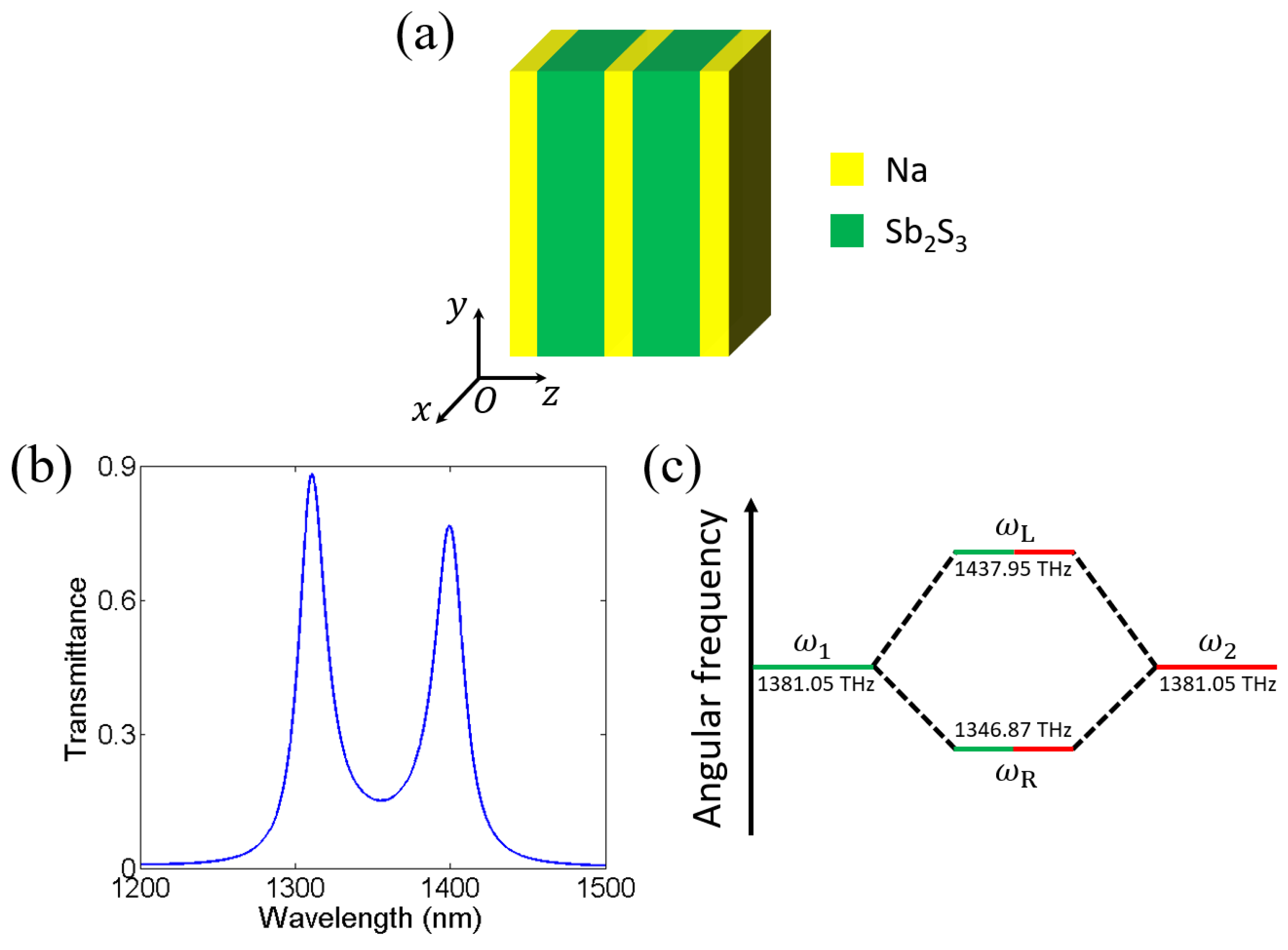
Next, we cascaded two Fabry–Perot cavities together to construct a multilayer MDMDM, i.e., (MD)2M, as schematically shown in Figure 4a. The thicknesses of the Na and Sb2S3 layers remain unchanged. Figure 4b demonstrates the transmittance spectrum of the cascaded Fabry–Perot cavities (MD)2M at normal incidence. In this case, two transmittance peaks occur. The left transmittance peak occurs at wavelength   λ L = 1310.9   n m and the right one occurs at wavelength λ R = 1399.5   n m . The transmittances of two transmittance peaks are 0.884 and 0.769, respectively. The Q factor of the left transmittance peak can be calculated as Q L = ω L / ω L = 1437.95   T H z / 23.80   T H z = 60.4 . The Q factor of the right transmittance peak can be calculated as Q R = ω R / ω R = 1346.87   T H z / 23.12   T H z = 58.3 . Owing to the mode coupling, the Q factors of the two transmittance peaks in the cascaded Fabry–Perot cavities (MD)2M are higher than the Q factor of the transmittance peak in the single Fabry–Perot cavity MDM.
Now, we explain the formation of two transmittance peaks from the perspective of the mode coupling, as schematically shown in Figure 4c. The resonant angular frequencies of two single Fabry–Perot cavities are denoted by ω 1 and ω 2 . In our design, two single Fabry–Perot cavities are identical, i.e., ω 1 =   ω 2 = 1381.05   T H z . The cascaded Fabry–Perot cavities (MD)2M can be treated as a system composed of two coupled oscillators. According to the coupled oscillator model [53,54,55,56,57,58,59,60], the Hamiltonian of the system can be determined by:
H = ω 1 + i Γ 1 Ω C Ω C ω 2 + i Γ 2
where ω 1 and ω 2 denote the resonant angular frequencies of two single Fabry–Perot cavities, Γ 1 and Γ 2 denote the half widths at half-maximum of two single Fabry–Perot cavities, and Ω C denotes the coupling strength between two Fabry–Perot modes. In our design, ω 1 = ω 2 = ω 0 = 1381.05   T H z and Γ 1 = Γ 2 = Γ 0 = 21.33   T H z . Therefore, Equation (5) reduces to:
H = ω 1 + i Γ 1 Ω C Ω C ω 2 + i Γ 2
Two eigen-angular frequencies can be given by:
ω L = ω 0 + Ω C + i Γ 0
ω R = ω 0 Ω C + i Γ 0
Hence, the Rabi splitting can be calculated by [53,54,55,56,57,58,59,60]:
Ω R a b i = ω L ω R = 2 Ω C
According to Equations (7) and (8), the angular frequency of the Fabry–Perot mode splits into two angular frequencies owing to the mode coupling. Hence, the transmittance peak splits into two transmittance peaks. Substituting ω L = 1437.95   T H z and ω R = 1346.87   T H z into Equation (9), the Rabi splitting can be obtained as Ω R a b i = 60.0   m e V . According to Equation (9), the two angular frequencies of two hybrid modes are symmetrical with respect to the angular frequency of the single Fabry–Perot mode. However, from Figure 3c, the two angular frequencies of two hybrid modes exhibit a weak asymmetry with respect to the angular frequency of the single Fabry–Perot mode. The underlying reason is that the Q factor of the single Fabry–Perot mode Q = 32.4 is not very high due to the optical loss of the Na layers. Hence, the resonant strength of the Fabry–Perot mode is not too strong, giving rise to a weak inaccuracy of the coupled oscillator model.
To achieve a near-infrared transparent band, we cascaded four Fabry–Perot cavities together to construct a multilayer (MD)4M, as schematically shown in Figure 5a. Figure 5b demonstrates the transmittance spectrum of the cascaded Fabry–Perot cavities (MD)4M at normal incidence. Now, four transmittance peaks occur owing to the coupling between five Fabry–Perot modes. Specifically, four transmittance peaks occur at the wavelengths of 1277.6, 1324.8, 1378.1, and 1420.8 nm. The bandwidth of the near-infrared transparent band is 143.2 nm. The average wavelength difference between the four transmittance peaks is 47.8 nm. The transmittances of the four transmittance peaks are 0.843, 0.812, 0.740, and 0.503. By cascading four Fabry–Perot cavities, we achieve a near-infrared transparent band. Compared with the reported transparent bands based on cascaded Fabry–Perot cavities [29,30,31,32,33,34], the transmittance of the transparent band in this work is higher.
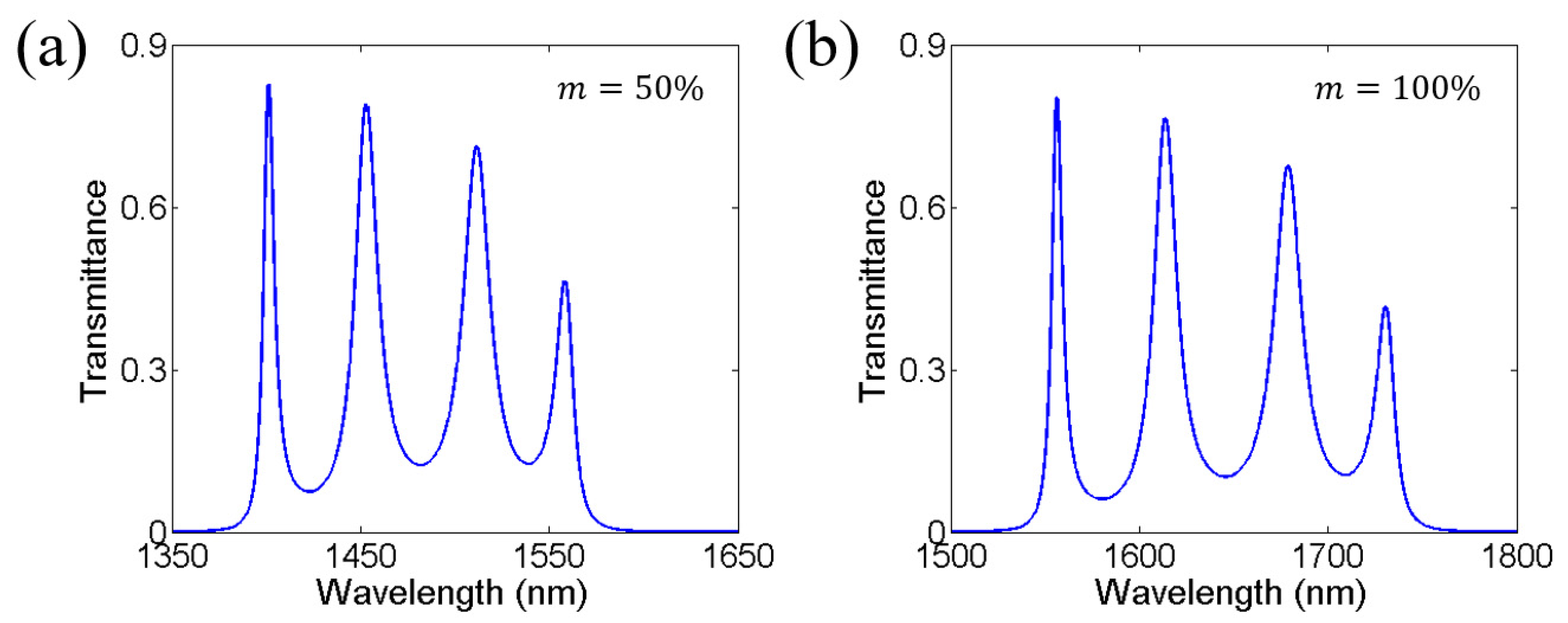
Next, we changed the crystalline fraction of the Sb2S3 layers to investigate the tunability of the near-infrared transparent band. Figure 6a gives the transmittance spectrum of the cascaded Fabry–Perot cavities (MD)4M at normal incidence for m = 50 % . Four transmittance peaks occur at the wavelengths of 1401.3, 1453.2, 1511.6, and 1559.3 nm. The bandwidth of the near-infrared transparent band is 157.0 nm. The average wavelength difference between the four transmittance peaks is 52.3 nm. The transmittances of the four transmittance peaks are 0.828, 0.794, 0.714, and 0.466. Figure 6b gives the transmittance spectrum of the cascaded Fabry–Perot cavities (MD)4M at normal incidence for m = 100 % . Four transmittance peaks occur at the wavelengths of 1556.3, 1613.7, 1678.8, and 1730.5 nm. The bandwidth of the near-infrared transparent band is 174.2 nm. The average wavelength difference between the four transmittance peaks is 58.1 nm. The transmittances of the four transmittance peaks are 0.805, 0.766, 0.679, and 0.418. The near-infrared transparent band can be flexibly tuned by the crystalline fraction of the Sb2S3 layers. As the crystalline fraction of the Sb2S3 layers changes from 0% to 100%, the short-wavelength edge of the near-infrared transparent band can be tuned from 1277.6 to 1556.3 nm and the long-wavelength edge of the near-infrared transparent band can be tuned from 1420.8 to 1730.5 nm.
Finally, we discuss the fabrication scheme of the proposed cascaded Fabry–Perot cavities. The proposed cascaded Fabry–Perot cavities are multilayers composed of Na and Sb2S3 films. It is known that both Na films [47] and Sb2S3 films [61] can be fabricated by the spin-coating technique. In addition, the crystalline fraction of Sb2S3 film can be flexibly controlled by the power density of a continuous-wave laser [50]. Therefore, the tunable near-infrared transparent band would be achieved using the spin-coating and continuous-wave lasing techniques.

3. Effects of Layer Thickness and Incident Angle on Near-Infrared Transparent Bands and Mode Coupling

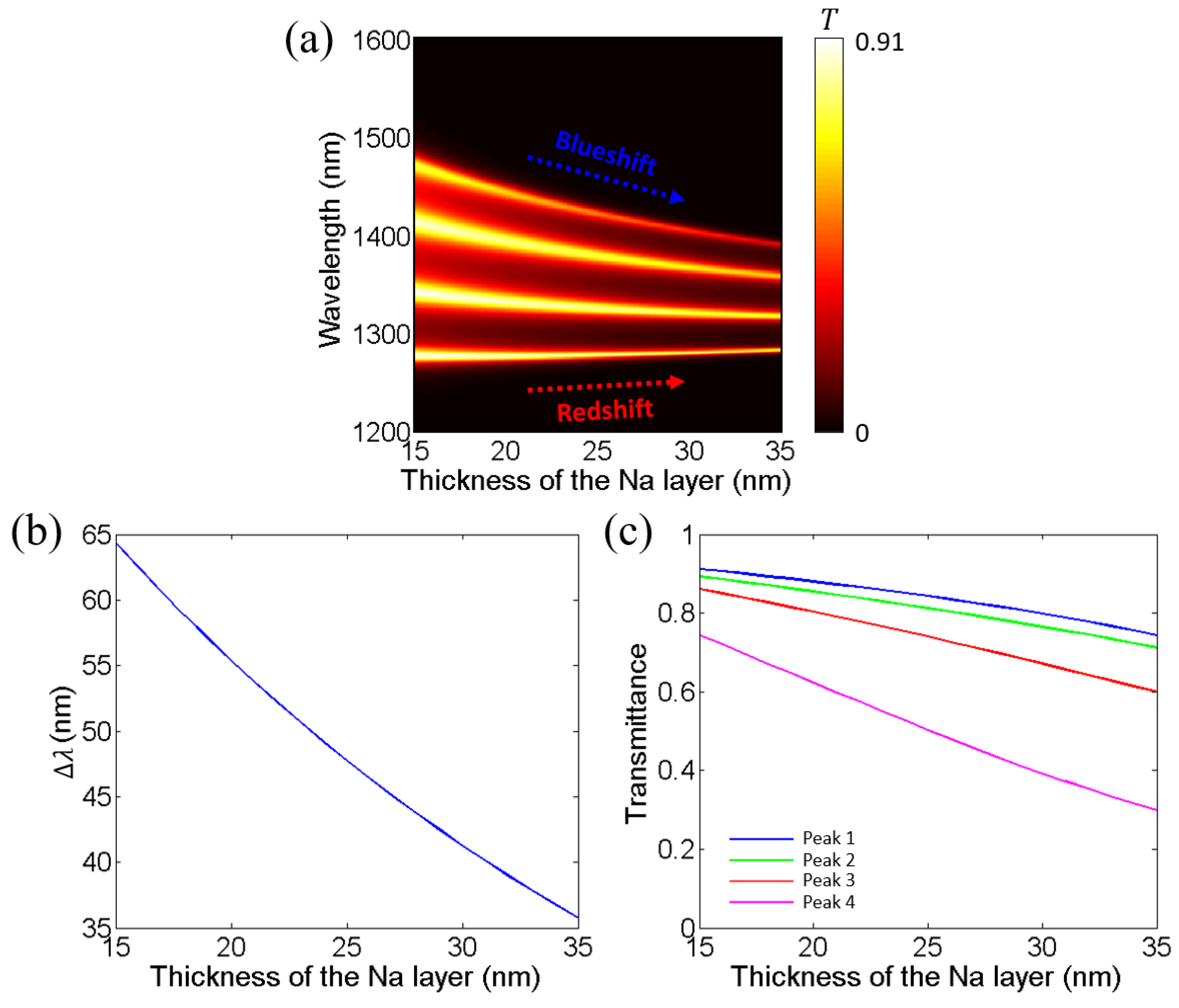
According to the Fabry–Perot resonant condition (Equation (3)) and the coupled oscillators model, both the layer thickness and incident angle will affect the near-infrared transparent band and the mode coupling. In this section, the crystalline fraction of the Sb2S3 layers is kept as m = 0 % . Now, we investigate the effect of the thickness of the Na layer on the near-infrared transparent band and the mode coupling in Figure 7. Figure 7a gives the dependence of the transmittance spectrum of the cascaded Fabry–Perot cavities (MD)4M at normal incidence on the thickness of the Na layer. The thickness of the Na layer is changed from 15 to 35 nm while the thickness of the Sb2S3 layer and the incident angle are the same as those in Section 2. As the thickness of the Na layer increases, the four transmittance peaks become closer. In other words, the bandwidth of the transparent band becomes smaller. Specifically, when the thickness of the Na layer is 15 nm, the transparent band ranges from 1276.9 to 1470.0 nm. The bandwidth of the transparent band is 193.1 nm. When the thickness of the Na layer increases to 35 nm, the transparent band ranges from 1282.4 to 1389.5 nm. The bandwidth of the transparent band is 107.1 nm. Figure 7b gives the dependence of the average wavelength difference between the four transmittance peaks λ on the thickness of the Na layer. As the thickness of the Na layer increases from 15 to 35 nm, the average wavelength difference between the four transmittance peaks decreases from 64.3 to 35.7 nm. The underlying reason can be explained as follows. As the thickness of the Na layer increases, the reflectance of the Na layer increases. Consequently, the electric field of the Fabry–Perot cavity becomes more localized, leading to a smaller coupling strength between different Fabry–Perot modes. According to Equation (9), the Rabi splitting becomes smaller. In addition, we give the dependences of the transmittances of the four transmittance peaks on the thickness of the Na layer, as shown in Figure 7c. As the thickness of the Na layer increases from 15 to 35 nm, the transmittances of the four transmittance peaks decrease. Specifically, the transmittance of transmittance peak 1 decreases from 0.912 to 0.743. The transmittance of transmittance peak 2 decreases from 0.893 to 0.712. The transmittance of transmittance peak 3 decreases from 0.861 to 0.600. The transmittance of transmittance peak 4 decreases from 0.743 to 0.298.
Then, we investigated the effect of the thickness of the Sb2S3 layer on the near-infrared transparent band and mode coupling, as shown in Figure 8. Figure 8a gives the dependence of the transmittance spectrum of the cascaded Fabry–Perot cavities (MD)4M at normal incidence on the thickness of the Sb2S3 layer. The thickness of the Sb2S3 layer is changed from 850 to 950 nm while the thickness of the Na layer and the incident angle are the same as those in Section 2. As the thickness of the Sb2S3 layer increases, five transmittance peaks shift towards longer wavelengths (i.e., redshift). Specifically, when the thickness of the Sb2S3 layer is 850 nm, the transparent band ranges from 1222.2 to 1362.0 nm. The bandwidth of the transparent band is 139.8 nm. When the thickness of the Sb2S3 layer is 950 nm, the transparent band ranges from 1360.6 to 1508.6 nm. The bandwidth of the transparent band is 148.0 nm. The underlying reason can be explained as follows. As the thickness of the Sb2S3 layer increases, the round-trip propagating phase of the Sb2S3 layer for a fixed wavelength increases. As a result, the wavelength satisfying the Fabry–Perot resonant condition (Equation (3)) becomes larger, giving rise to the redshift of the transparent band. Figure 8b gives the dependence of the average wavelength difference between four transmittance peaks λ on the thickness of the Sb2S3 layer. As the thickness of the Sb2S3 layer increases from 850 to 950 nm, the average wavelength difference between the four transmittance peaks increases from 46.6 to 49.4 nm. In addition, we give the dependences of the transmittances of the four transmittance peaks on the thickness of the Sb2S3 layer, as shown in Figure 8c. As the thickness of the Sb2S3 layer increases from 850 to 950 nm, the transmittances of the four transmittance peaks slightly decrease. Specifically, the transmittance of transmittance peak 1 decreases from 0.848 to 0.834. The transmittance of transmittance peak 2 decreases from 0.820 to 0.799. The transmittance of transmittance peak 3 decreases from 0.753 to 0.718. The transmittance of transmittance peak 4 decreases from 0.527 to 0.466.
Finally, we investigated the effect of the incident angle on the near-infrared transparent band and the coupling. The thicknesses of the Na and Sb2S3 layers are the same as those in Section 2. At normal incidence, the transmittance spectra of the cascaded Fabry–Perot cavities (MD)4M under transverse magnetic (TM) and transverse electric (TE) polarizations are identical due to the axial symmetry. Nevertheless, under oblique incidence, the transmittance spectra of the cascaded Fabry–Perot cavities (MD)4M under TM and TE polarizations are different since the axial symmetry is broken. Hence, we should discuss TM and TE polarizations separately. Figure 9a gives the dependence of the transmittance spectrum of the cascaded Fabry–Perot cavities (MD)4M on the incident angle under TM polarization. As the incident angle increases, four transmittance peaks shift towards shorter wavelengths (i.e., blueshift) under TM polarization. Specifically, when the incident angle is 0°, the transparent band ranges from 1277.6 to 1420.8 nm. The bandwidth of the transparent band is 143.2 nm. When the incident angle increases to ~90°, the transparent band under TM polarization ranges from 1182.9 to 1326.1 nm. The bandwidth of the transparent band is 143.2 nm. The underlying reason can be explained as follows. As the incident angle increases, the round-trip propagating phase of the Sb2S3 layer for a fixed wavelength decreases. As a result, the wavelength satisfying the Fabry–Perot resonant condition (Equation (3)) becomes smaller, giving rise to the blueshift of the transparent band. Figure 9b gives the dependence of the average wavelength difference between four transmittance peaks λ on the incident angle under TM polarization. As the incident angle increases from 0° to ~90°, the average wavelength difference between the four transmittance peaks first decreases from 47.7 to 45.5 nm and then increases to 47.8 nm. In addition, we give the dependences of the transmittances of the four transmittance peaks on the incident angle under TM polarization, as shown in Figure 9c. As the incident angle increases from 0° to ~90°, the transmittances of the four transmittance peaks first increase and then decrease. Specifically, the transmittance of transmittance peak 1 first increases from 0.843 to 0.962, and then decreases to 0. The transmittance of transmittance peak 2 first increases from 0.812 to 0.936, and then decreases to 0. The transmittance of transmittance peak 3 first increases from 0.740 to 0.887, and then decreases to 0. The transmittance of transmittance peak 4 first increases from 0.503 to 0.734, and then decreases to 0.
Figure 10a gives the dependence of the transmittance spectrum of the cascaded Fabry–Perot cavities (MD)4M on the incident angle under TE polarization. As the incident angle increases, four transmittance peaks shift towards shorter wavelengths (i.e., blueshift) under TE polarization. Specifically, when the incident angle is 0°, the transparent band ranges from 1277.6 to 1420.8 nm. The bandwidth of the transparent band is 143.2 nm. When the incident angle increases to ~90°, the transparent band under TE polarization ranges from 1189.8 to 1322.5 nm. The bandwidth of the transparent band is 132.7 nm. The underlying reason can be explained as follows. As the incident angle increases, the round-trip propagating phase of the Sb2S3 layer for a fixed wavelength decreases. As a result, the wavelength satisfying the Fabry–Perot resonant condition (Equation (3)) becomes smaller, giving rise to the blueshift of the transparent band. Figure 10b gives the dependence of the average wavelength difference between four transmittance peaks λ on the incident angle under TE polarization. As the incident angle increases from 0° to ~90°, the average wavelength difference between the four transmittance peaks decreases from 47.7 to 44.2 nm. In addition, we give the dependences of the transmittances of four transmittance peaks on the incident angle under TE polarization, as shown in Figure 10c. As the incident angle increases from 0° to ~90°, the transmittances of the four transmittance peaks gradually decrease. Specifically, the transmittance of transmittance peak 1 decreases from 0.843 to 0. The transmittance of transmittance peak 2 decreases from 0.812 to 0. The transmittance of transmittance peak 3 decreases from 0.740 to 0. The transmittance of transmittance peak 4 decreases from 0.503 to 0.

4. Conclusions

In summary, we realized a near-infrared transparent band by cascading four Na/Sb2S3/Na Fabry–Perot cavities. The near-infrared transparent band originates from the mode coupling between four Fabry–Perot modes. By changing the crystalline fraction of the Sb2S3 layers, the near-infrared transparent band can be flexibly tuned. As the crystalline fraction of the Sb2S3 layers changes from 0% to 100%, the short-wavelength edge of the near-infrared transparent band can be tuned from 1277.6 to 1556.3 nm and the long-wavelength edge of the near-infrared transparent band can be tuned from 1420.8 to 1730.5 nm. In addition, we studied the effects of layer thickness and incident angle on the near-infrared transparent band and mode coupling. As the thickness of the Na layer increases, the bandwidth of the near-infrared transparent band becomes smaller. As the thickness of the Sb2S3 layer increases, the near-infrared transparent band shifts towards longer wavelengths. As the incident angle increases, the near-infrared transparent band shifts towards shorter wavelengths. These results not only provide a viable route to achieving tunable near-infrared transparent bands but also possess potential applications in high-performance display, filtering, and sensing.

Author Contributions

Conceptualization, F.W.; methodology, Y.S., S.X. and F.W.; software, Y.S., K.Z. and F.W.; validation, Y.S. and F.W.; formal analysis, Y.S. and F.W.; investigation, Y.S. and F.W.; resources, F.W.; writing—original draft preparation, Y.S. and F.W.; writing—review and editing, Y.S., K.Z., M.T., S.X., Z.C., Y.A., D.L. and F.W.; visualization, Y.S. and F.W.; supervision, F.W.; project administration, F.W.; funding acquisition, S.X., Z.C., Y.A., D.L. and F.W. All authors have read and agreed to the published version of the manuscript.

Funding

This research was funded by the National Natural Science Foundation of China (12104105, 12264028, 12304420, 62205211, 62004047), the Guangdong Basic and Applied Basic Research Foundation (2023A1515011024), the Natural Science Foundation of Jiangxi Province (20232BAB201040), the Special Projects in Key Fields of Artificial Intelligence in Colleges and Universities of Guangdong Province (2019KZDZX1042), and the Start-up Funding of Guangdong Polytechnic Normal University (2021SDKYA033).

Institutional Review Board Statement

Not applicable.

Informed Consent Statement

Not applicable.

Data Availability Statement

The original contributions presented in this study are included in the article, further inquiries can be directed to the corresponding author.

Conflicts of Interest

The authors declare no conflicts of interest.

References

  1. Miroshnichenko, A.E.; Flach, S.; Kivshar, K.S. Fano resonances in nanoscale structures. Rev. Mod. Phys. 2010, 82, 2257–2298. [Google Scholar] [CrossRef]
  2. Zangeneh-Nejad, F.; Fleury, R. Topological Fano resonances. Phys. Rev. Lett. 2019, 122, 014301. [Google Scholar] [CrossRef] [PubMed]
  3. Wu, F.; Qi, X.; Qin, M.; Luo, M.; Long, Y.; Wu, J.; Sun, Y.; Jiang, H.; Liu, T.; Xiao, S.; et al. Momentum mismatch driven bound states in the continuum and ellipsometric phase singularities. Phys. Rev. B 2024, 109, 085436. [Google Scholar] [CrossRef]
  4. Marburger, J.H.; Felber, F.S. Theory of a lossless nonlinear Fabry–Perot interferometer. Phys. Rev. A 1978, 17, 335–342. [Google Scholar] [CrossRef]
  5. Stadt, H.; Muller, J.M. Multimirror fabry–perot interferometers. J. Opt. Soc. Am. A 1985, 2, 1363–1370. [Google Scholar] [CrossRef]
  6. Zuo, C.; Wu, K.; Shi, J.; Guang, D.; Wu, X.; Yu, B. Ultrasensitive temperature sensor based on cascading a polarization mode interferometer with a Fabry–Perot interferometer. Opt. Laser Technol. 2024, 168, 109910. [Google Scholar] [CrossRef]
  7. Zhang, H.-Y.; Gao, Y.; Zhang, Y.-P.; Wang, S.-F. Independently tunable multichannel terahertz filters. Chin. Phys. B 2011, 20, 094101. [Google Scholar] [CrossRef]
  8. Moiseev, S.G.; Glukhov, I.A.; Dadoenkova, Y.S.; Bentivegna, F.F. Polarization-selective defect mode amplification in a photonic crystal with intracavity 2D arrays of metallic nanoparticles. J. Opt. Soc. Am. B 2019, 36, 1645–1652. [Google Scholar] [CrossRef]
  9. Zhang, T.; Zhang, D.; Zhang, H.-F. Realization of double Fano resonances with a InSb-doped Fabry–Perot cavity. Results Phys. 2022, 35, 105417. [Google Scholar] [CrossRef]
  10. Gryga, M.; Ciprian, D.; Gembalova, L.; Hlubina, P. One-dimensional photonic crystal with a defect layer utilized as an optical filter in narrow linewidth LED-based sources. Crystals 2023, 13, 93. [Google Scholar] [CrossRef]
  11. Li, S.; Feng, G.; Liu, Y.; Wu, M.; Zhao, X.; Sun, F.; Gan, Z.; Chen, Z.; Yang, Y. Omnidirectional near-infrared narrowband filters based on defective mirror-symmetry one-dimensional photonic crystals containing hyperbolic metamaterials. Opt. Laser Eng. 2024, 176, 108107. [Google Scholar] [CrossRef]
  12. Wu, J.; Zeng, R.; Liang, J.; Huang, D.; Dai, X.; Xiang, Y. Spin-dependent and tunable perfect absorption in a Fabry–Perot cavity containing a multi-Weyl semimetal. Opt. Express 2023, 31, 30079–30091. [Google Scholar] [CrossRef] [PubMed]
  13. Zhang, Y.G.; Liu, W.; Yao, H.Y.; Liang, L.J.; Yan, X.; Zong, M.J.; Gao, S.; Huang, C.C.; Qiu, F.; Feng, Z.W.; et al. Broad/narrowband switchable terahertz absorber based on Dirac semimetal and strontium titanate for temperature sensing. Appl. Opt. 2024, 63, 1306–1312. [Google Scholar] [CrossRef] [PubMed]
  14. Uphoff, M.; Brekenfeld, M.; Rempe, G.; Ritter, S. Frequency splitting of polarization eigenmodes in microscopic Fabry–Perot cavities. New J. Phys. 2017, 17, 013053. [Google Scholar] [CrossRef]
  15. Wu, F.; Chen, M.; Xiao, S. Wide-angle polarization selectivity based on anomalous defect mode in photonic crystal containing hyperbolic metamaterials. Opt. Lett. 2022, 47, 2153–2156. [Google Scholar] [CrossRef] [PubMed]
  16. Villa, F.; Lopez-Rios, T.; Regalado, L.E. Electromagnetic modes in metal-insulator-metal structures. Phys. Rev. B 2001, 63, 165103. [Google Scholar] [CrossRef]
  17. Li, Z.; Butun, S.; Aydin, K. Large-area, lithography-free super absorbers and color filters at visi1ble frequencies using ultrathin metallic films. ACS Photonics 2015, 2, 183–188. [Google Scholar] [CrossRef]
  18. Lv, J.; Chen, D.; Du, Y.; Wang, T.; Zhang, X.; Li, Y.; Zhang, L.; Wang, Y.; Jordan, R.; Fu, Y. Visual detection of thiocyanate based on Fabry–Perot etalons with a responsive polymer brush as the transducer. ACS Sens. 2020, 5, 303–307. [Google Scholar] [CrossRef] [PubMed]
  19. Taal, A.J.; Lee, C.; Choi, J.; Hellenkamp, B.; Shepard, K.L. Toward implantable devices for angle-sensitive, lens-less, multifluorescent, single-photon lifetime imaging in the brain using Fabry–Perot and absorptive color filters. Light Sci. Appl. 2022, 11, 24. [Google Scholar] [CrossRef] [PubMed]
  20. Shu, S.; Li, Z.; Li, Y.Y. Triple-layer Fabry–Perot absorber with near-perfect absorption in visible and near-infrared regime. Opt. Express 2013, 21, 25307–25315. [Google Scholar] [CrossRef]
  21. Zhao, D.; Meng, L.; Gong, H.; Chen, X.; Chen, Y.; Yan, M.; Li, Q.; Qiu, M. Ultra-narrow-band light dissipation by a stack of lamellar silver and alumina. Appl. Phys. Lett. 2014, 104, 221107. [Google Scholar] [CrossRef]
  22. Kocer, H.; Butun, S.; Li, Z.; Aydin, K. Reduced near-infrared absorption using ultra-thin lossy metals in Fabry–Perot cavities. Sci. Rep. 2015, 5, 8157. [Google Scholar] [CrossRef]
  23. Li, Z.; Palacios, E.; Butun, S.; Kocer, H.; Aydin, K. Omnidirectional, broadband light absorption using large-area, ultrathin lossy metallic film coatings. Sci. Rep. 2015, 5, 15137. [Google Scholar] [CrossRef] [PubMed]
  24. Mirshafieyan, S.S.; Luk, T.S.; Guo, J. Zeroth order Fabry–Perot resonance enabled ultra-thin perfect light absorber using percolation aluminum and silicon nanofilms. Opt. Mater. Express 2016, 6, 1032–1042. [Google Scholar] [CrossRef]
  25. Sreekanth, K.V.; Ouyang, Q.; Han, S.; Yong, K.T.; Singh, R. Giant enhancement in Goos-Hänchen shift at the singular phase of a nanophotonic cavity. Appl. Phys. Lett. 2018, 112, 161109. [Google Scholar] [CrossRef]
  26. Liu, F.; Shi, H.; Zhu, X.; Dai, P.; Lin, Z.; Long, Y.; Xie, Z.; Zhou, Y.; Duan, H. Tunable reflective color filters based on asymmetric Fabry–Perot cavities employing ultrathin Ge2Sb2Te5 as a broadband absorber. Appl. Opt. 2018, 57, 9040–9045. [Google Scholar] [CrossRef]
  27. Chen, W.; Liu, J.; Ma, W.Z.; Yu, G.X.; Chen, J.Q.; Cai, H.Y.; Yang, C.F. Numerical study of multilayer planar film structures for ideal absorption in the entire solar spectrum. Appl. Sci. 2020, 10, 3276. [Google Scholar] [CrossRef]
  28. Liu, C.; Wang, G.; Zhang, L.; Fan, F.; Zhang, X.; Fu, Y.; Wang, T. Dynamic color display with viewing-angle tolerance based on the responsive asymmetric Fabry–Perot cavity. ACS Appl. Mater. Interfaces 2022, 14, 7200–7207. [Google Scholar] [CrossRef] [PubMed]
  29. Scalora, M.; Bloemer, M.J.; Pethel, A.S.; Dowling, J.P.; Bowden, C.M.; Manka, A.S. Transparent, metallo-dielectric, one-dimensional, photonic band-gap structures. J. Appl. Phys. 1998, 83, 2377–2383. [Google Scholar] [CrossRef]
  30. Bloemer, M.J.; Scalora, M. Transmissive properties of Ag/MgF2 photonic band gaps. Appl. Phys. Lett. 1998, 72, 1676–1678. [Google Scholar] [CrossRef]
  31. Kee, C.-S.; Kim, K.; Lim, H. Optical resonant transmission in metal-dielectric multilayers. J. Opt. A Pure Appl. Opt. 2004, 6, 22–25. [Google Scholar] [CrossRef]
  32. Zhang, J.-L.; Jiang, H.-T.; Shen, W.-D.; Liu, X.; Li, Y.-Y.; Gu, P.-F. Omnidirectional transmission bands of one-dimensional metal-dielectric periodic structures. J. Opt. Soc. Am. B 2008, 25, 1474–1478. [Google Scholar] [CrossRef]
  33. Zhang, M.C.; Allen, T.W.; Drobot, B.; McFarlane, S.; Meldrum, A.; DeCorby, R.G. Transparency and stability of Ag-based metal-dielectric multilayers. Appl. Opt. 2013, 52, 7479–7485. [Google Scholar] [CrossRef]
  34. Briones, E.; Sanchez, S.; Vergara, C.; Briones, J. Reflective color filters based on SiO2/Cu multilayer stacks. J. Appl. Phys. 2023, 134, 083101. [Google Scholar] [CrossRef]
  35. Belyaev, V.; Zverev, N.; Abduev, A.; Zotov, A. E-wave interaction with the one-dimensional photonic crystal with weak conductive and transparent materials. Coatings 2023, 13, 712. [Google Scholar] [CrossRef]
  36. Bikbaev, R.G.; Maksimov, D.N.; Pankin, P.S.; Chen, K.P.; Timofeev, I.V. Critical coupling vortex with grating-induced high Q-factor optical Tamm states. Opt. Express 2021, 29, 4672–4680. [Google Scholar] [CrossRef]
  37. Wu, F.; Wu, X.; Xiao, S.; Liu, G.; Li, H. Broadband wide-angle multilayer absorber based on a broadband omnidirectional optical Tamm state. Opt. Express 2021, 29, 23976–23987. [Google Scholar] [CrossRef] [PubMed]
  38. Li, H.; Zheng, G. Excitation of Hybrid Waveguide-Bloch surface states with Bi2Se3 plasmonic material in the near-infrared range. Micromachines 2022, 13, 1020. [Google Scholar] [CrossRef]
  39. Wu, F.; Li, X.; Fan, X.; Lin, L.; Taya, S.A.; Panda, A. Wide-angle absorption based on angle-insensitive light slowing effect in photonic crystal containing hyperbolic metamaterials. Photonics 2022, 9, 181. [Google Scholar] [CrossRef]
  40. Huang, C.H.; Wu, C.H.; Bikbaev, R.G.; Ye, M.J.; Chen, C.W.; Wang, T.J.; Timofeev, I.V.; Lee, W.; Chen, K.P. Wavelength-and angle-selective photodetectors enabled by graphene hot electrons with Tamm plasmon polaritons. Nanomaterials 2023, 13, 693. [Google Scholar] [CrossRef]
  41. Barone, P.W.; Baik, S.; Heller, D.A.; Strano, M.S. Near-infrared optical sensors based on single-walled carbon nanotubes. Nat. Mater. 2015, 4, 86–92. [Google Scholar] [CrossRef] [PubMed]
  42. Hakkel, K.D.; Petruzzella, M.; Ou, F.; Klinken, A.; Pagliano, F.; Liu, T.; Veldhoven, R.P.J.; Fiore, A. Integrated near-infrared spectral sensing. Nat. Commun. 2022, 13, 103. [Google Scholar] [CrossRef] [PubMed]
  43. Liu, X.; Zhang, C.; Hu, J.; Han, H. Dual-band refractive index sensor with cascaded asymmetric resonant compound grating based on bound states in the continuum. Opt. Express 2023, 31, 13959–13969. [Google Scholar] [CrossRef] [PubMed]
  44. Wu, F.; Liu, T.; Xiao, S. Polarization-sensitive photonic bandgaps in hybrid one-dimensional photonic crystals composed of all-dielectric elliptical metamaterials and isotropic dielectrics. Appl. Opt. 2023, 62, 706–713. [Google Scholar] [CrossRef] [PubMed]
  45. Wang, E.W.; Yu, S.-J.; Phan, T.; Dhuey, S.; Fan, J.A. Arbitrary achromatic polarization control with reconfigurable metasurface systems. Laser Photonics Rev. 2023, 17, 2200926. [Google Scholar] [CrossRef]
  46. She, Y.; Liu, D.; Li, J.; Yao, M.; Zheng, Y.; Wu, F. Tunable wide-angle high-efficiency polarization selectivity based on a one-dimensional photonic crystal containing elliptical metamaterials. Phys. Lett. A 2024, 494, 129299. [Google Scholar] [CrossRef]
  47. Wang, Y.; Yu, J.; Mao, Y.-F.; Chen, J.; Wang, S.; Chen, H.-Z.; Zhang, Y.; Wang, S.-Y.; Chen, X.; Li, T.; et al. Stable, high-performance sodium-based plasmonic devices in the near infrared. Nature 2020, 581, 401–405. [Google Scholar] [CrossRef] [PubMed]
  48. Rawashdeh, A.; Lupa, S.; Welch, W.; Yang, A. Sodium surface lattice plasmons. J. Phys. Chem. C 2021, 125, 25148–25154. [Google Scholar] [CrossRef]
  49. Delaney, M.; Zeimpekis, I.; Lawson, D.; Hewak, D.W.; Muskens, O.L. A new family of ultralow loss reversible phase-change materials for photonic integrated circuits: Sb2S3 and Sb2Se3. Adv. Funct. Mater. 2020, 30, 2002447. [Google Scholar] [CrossRef]
  50. Jana, S.; Sreekanth, K.V.; Abdelraouf, O.A.M.; Lin, R.; Liu, H.; Teng, J.; Singh, R. Aperiodic Bragg reflectors for tunable high-purity structural color based on phase change material. Nano Lett. 2024, 24, 3922–3929. [Google Scholar] [CrossRef]
  51. Liu, T.; Zhang, D.; Liu, W.; Yu, T.; Wu, F.; Xiao, S.; Huang, L.; Miroshnichenko, A.E. Phase-change nonlocal metasurfaces for dynamic wave-front manipulation. Phys. Rev. Appl. 2024, 21, 044004. [Google Scholar] [CrossRef]
  52. Yeh, P. Optical Waves in Layered Media; Wiley: Hoboken, NJ, USA, 1988. [Google Scholar]
  53. Hu, J.; Liu, W.; Xie, W.; Zhang, W.; Yao, E.; Zhang, Y.; Zhan, Q. Strong coupling of optical interface modes in a 1D topological photonic crystal heterostructure/Ag hybrid system. Opt. Lett. 2019, 44, 5642–5645. [Google Scholar] [CrossRef] [PubMed]
  54. Hu, J.; Yao, E.; Xie, W.; Liu, W.; Li, D.; Lu, Y.; Zhan, Q. Strong longitudinal coupling of Tamm plasmon polaritons in graphene/DBR/Ag hybrid structure. Opt. Express 2019, 27, 18642–18652. [Google Scholar] [CrossRef] [PubMed]
  55. Gao, H.; Li, P.; Yang, S. Tunable multichannel optical absorber based on coupling effects of optical Tamm states in metal-photonic crystal heterostructure-metal structure. Opt. Commun. 2020, 457, 124688. [Google Scholar] [CrossRef]
  56. Pankin, P.S.; Sutormin, V.S.; Gunyakov, V.A.; Zelenov, F.V.; Tambasov, I.A.; Masyugin, A.N.; Volochaev, M.N.; Baron, F.A.; Chen, K.P.; Zyryanov, V.Y.; et al. Experimental implementation of tunable hybrid Tamm-microcavity modes. Appl. Phys. Lett. 2021, 119, 161107. [Google Scholar] [CrossRef]
  57. Jena, S.; Tokas, R.B.; Thakur, S.; Udupa, D.V. Rabi-like splitting and refractive index sensing with hybrid Tamm plasmon-cavity modes. J. Phys. D Appl. Phys. 2022, 55, 175104. [Google Scholar] [CrossRef]
  58. Xu, W.-H.; Chou, Y.-H.; Yang, Z.-Y.; Liu, Y.-Y.; Yu, M.-W.; Huang, C.-H.; Chang, C.-T.; Huang, C.-Y.; Lu, T.-C.; Lin, T.-R.; et al. Tamm plasmon-polariton ultraviolet lasers. Adv. Photonics Res. 2022, 3, 2100120. [Google Scholar] [CrossRef]
  59. Liu, Q.; Zhao, X.; Li, C.; Zhou, X.; Chen, Y.; Wang, S.; Lu, W. Coupled Tamm plasmon polaritons induced narrow bandpass filter with ultra-wide stopband. Nano Res. 2022, 15, 4563–4568. [Google Scholar] [CrossRef]
  60. Qin, K.; Deng, X.-H.; Zhang, P.; Guo, F.; Song, Y.; Tao, L.; Yuan, J. Tunable multiband THz perfect absorber due to the strong coupling of distributed Bragg reflector cavity mode and Tamm plasma polaritons modes based on MoS2 and graphene. Opt. Commun. 2024, 550, 129947. [Google Scholar] [CrossRef]
  61. Kaienburg, P.; Klingebiel, B.; Kirchartz, T. Spin-coated planar Sb2S3 hybrid solar cells approaching 5% efficiency. Beilstein J. Nanotechnol. 2018, 9, 2114–2124. [Google Scholar] [CrossRef]
Figure 1. (a) Real part and (b) imaginary part of the relative permittivity of Na as functions of the wavelength. (c) Reflectance spectrum of a Na layer with a thickness of 25 nm at normal incidence.
Photonics 11 00497 g001
Figure 2. Relative permittivity of Sb2S3 as a function of the crystalline fraction.
Photonics 11 00497 g002
Figure 3. (a) Schematic of the Fabry–Perot cavity MDM. (b) Transmittance spectrum of the Fabry–Perot cavity MDM at normal incidence. (c) Total phase as a function of the wavelength.
Photonics 11 00497 g003
Figure 4. (a) Schematic of the cascaded Fabry–Perot cavities (MD)2M. (b) Transmittance spectrum of the cascaded Fabry–Perot cavities (MD)2M at normal incidence. (c) Schematic of the coupling between two Fabry–Perot modes.
Photonics 11 00497 g004
Figure 5. (a) Schematic of the cascaded Fabry–Perot cavities (MD)4M. (b) Transmittance spectrum of the cascaded Fabry–Perot cavities (MD)4M at normal incidence for m = 0 % .
Photonics 11 00497 g005
Figure 6. Transmittance spectra of the cascaded Fabry–Perot cavities (MD)4M at normal incidence for (a) m = 50 % and (b) m = 100 % .
Photonics 11 00497 g006
Figure 7. (a) Dependence of the transmittance spectrum of the cascaded Fabry–Perot cavities (MD)4M at normal incidence on the thickness of the Na layer. (b) Dependence of the average wavelength difference between four transmittance peaks λ on the thickness of the Na layer. (c) Dependences of the transmittances of four transmittance peaks on the thickness of the Na layer.
Photonics 11 00497 g007
Figure 8. (a) Dependence of the transmittance spectrum of the cascaded Fabry–Perot cavities (MD)4M at normal incidence on the thickness of the Sb2S3 layer. (b) Dependence of the average wavelength difference between four transmittance peaks λ on the thickness of the Sb2S3 layer. (c) Dependences of the transmittances of four transmittance peaks on the thickness of the Sb2S3 layer.
Photonics 11 00497 g008
Figure 9. (a) Dependence of the transmittance spectrum of the cascaded Fabry–Perot cavities (MD)4M on the incident angle under TM polarization. (b) Dependence of the average wavelength difference between four transmittance peaks λ on the incident angle under TM polarization. (c) Dependences of the transmittances of four transmittance peaks on the incident angle under TM polarization.
Photonics 11 00497 g009
Figure 10. (a) Dependence of the transmittance spectrum of the cascaded Fabry–Perot cavities (MD)4M on the incident angle under TE polarization. (b) Dependence of the average wavelength difference between four transmittance peaks λ on the incident angle under TE polarization. (c) Dependences of the transmittances of four transmittance peaks on the incident angle under TE polarization.
Photonics 11 00497 g010
Disclaimer/Publisher’s Note: The statements, opinions and data contained in all publications are solely those of the individual author(s) and contributor(s) and not of MDPI and/or the editor(s). MDPI and/or the editor(s) disclaim responsibility for any injury to people or property resulting from any ideas, methods, instructions or products referred to in the content.