Abstract
This study reports new types of passive mode-locked Er-doped fiber laser (EDFL) based on a segment of doped fiber saturable absorber (DFSA) with Tm/Ho-doped fiber (THDF), Yb-doped fiber (YDF), and Er-doped fiber (EDF). By employing THDF-SA, a bright pulse sequence with a fundamental repetition rate of 17.86 MHz was obtained. In addition, various mode-locked output states, including dark pulses, dark–bright pulse pairs, bright–dark pulse pairs, and second-harmonic pulses, were obtained through polarization modulation and gain modulation, and the orthogonality of dark–bright pulses in both polarization directions was verified. Furthermore, using EDF-SA and YDF-SA, dark pulses and dark–bright pulses were obtained. A comparison of the three experiments revealed that THDF-SA effectively reduces the mode-locked threshold and improves the average output power. Compared with bright pulses, dark pulses offer several advantages such as resisting noise, increasing propagation speed, and suppressing nonlinear scattering (such as pulse-intrinsic Raman scattering); thus, the EDFL can find broad application in long-distance transmission, precision measurement, and other fields.
1. Introduction
Ultrafast fiber lasers find wide application in various fields, such as optical sensing [1], nonlinear optics [2], biomedical sciences [3], and material processing [4]. The 1.5 μm band lies in the third window of optical fiber communication, characterized by low transmission loss for long-distance transmission, and is often used in the field of optical fiber communication. Moreover, this band lies in the low-loss window of the atmosphere and the eye-safe band, providing considerable application prospects in areas such as satellite remote sensing [5] and lidar [6]. In addition, bright pulses, dark pulses, bright–dark pulse pairs, and dark–bright pulse pairs represent different output modes of mode-locked fiber lasers. Bright pulses suddenly rise from the background of continuous waves, whereas dark pulses suddenly decrease significantly from the background of continuous waves. Compared with bright pulses, dark pulses offer several advantages such as resisting noise, increasing propagation speed, and suppressing nonlinear scattering (such as pulse-intrinsic Raman scattering); thus, they can be widely used in long-distance transmission, precision measurement, and other fields. They significantly contribute to the advancement of advanced laser technologies and applications [7].
Research has shown that the abovementioned bright pulse, dark pulse, and pulse pairs are all steady-state solutions of the nonlinear Schrödinger equation (NLSE) in fiber optic systems [8]. Furthermore, they are also regarded as solutions of the complex Ginzburg–Landau equation (CGLE) [9,10]. There are three mechanisms for the formation of dark pulses: domain-wall (DW) dark pulses [11,12], NLSE dark pulses [13,14], and cubic-quintic nonlinear Schrödinger equation (CQNLSE) dark pulses [11]. DW dark pulses are generated when two or more lasers of different wavelengths oscillate, thereby causing topological defects in the temporal domain. They can occur in fiber cavities with normal and anomalous dispersion. NLSE-type dark pulses can exist only in cavities with normal dispersion and rely on the change in linear refractive index coefficient within the cavity. However, when a high nonlinear medium is introduced into a cavity with anomalous dispersion, CQNLSE-type dark pulses may occur. Compared with the other two types of dark pulses, the implementation of DW-type dark pulses can be more compact because they do not require any nonlinear medium.
Currently, ultrashort pulses are typically achieved using either Q-switched or mode-locked techniques. Due to the response speed limitations of modulators, Q-switched techniques can only achieve pulse widths on the nanosecond scale, whereas mode-locked techniques can produce pulses on the picosecond or femtosecond scale. Mode-locked techniques can be divided into active and passive mode-locked techniques. Active mode-locked techniques require the introduction of external modulation devices, while passive mode-locked techniques mainly utilize the nonlinear optical effects of saturable absorbers (SAs) within the cavity to generate ultrashort pulses [15]. Since passive mode-locking does not require the addition of external active modulation devices, it has a simpler structure, better stability, and is easier to implement in an all-fiber configuration. Additionally, the pulse width achieved with passive mode-locking is narrower than that obtained with active mode-locking. Material-based natural SAs, such as semiconductor saturable absorber mirrors (SESAM) [16], carbon nanotubes (CNT) [17], and graphene [18], are important devices for studying soliton nonlinear dynamics. However, owing to their complexity and high cost of production, their practicality is relatively low. Fiber saturable absorbers (FSAs), such as nonlinear multimode interference (NL-MMI) [19,20] and nonlinear polarization rotation (NPR) [21], provide more compact structures and have the advantages of low cost and long lifetime. Owing to differences in working mechanisms and designs, FSAs can be divided into two types: artificial fiber saturable absorbers (AFSAs), which include NALM, NPE, and NL-MMI; and doped fiber saturable absorbers (DFSAs). AFSAs significantly overcome the low damage threshold of natural SAs; however, they are sensitive to disturbances in the fiber cavity, which can affect the stability and controllability of fiber lasers. By contrast, common DFSAs include YDF working in the 1 μm wavelength range, EDF working in the 1.5 μm wavelength range, and THDF working in the 2 μm wavelength range (note that these are all single-mode fibers doped with metal ions). Overall, DFSAs hold significant research importance compared to other types of SAs due to advantages such as their high damage threshold, broadband operation, ease of integration, stability, and reliability. However, research on fiber lasers based on DFSAs has focused predominantly on the Q-switched laser rather than the mode-locked laser [22,23]. In 2013, Tao [24] et al. first reported an EDFL based on a DFSA in a ring cavity; the DFSA was composed of a 40 cm long THDF. By controlling polarization owing to the unadjusted dispersion and strong interaction between Tm and Ho ions, the pulse duration was reduced from 548 to 27.9 ns. Latiff [25] et al. observed self-starting dual-wavelength mode-locking in an EDFL using a 19 cm long THDF-SA. Zhang [26] et al. generated three-wavelength vector dark solitons in a all fiber ring cavity Er-doped fiber laser using a Bi-doped fiber SA. The authors of ref. [27] achieved ultrashort pulses in an EDFL using a 12 cm long TDF as an SA. In 2024, Zhang [28] et al. obtained the output of bright–dark pulse pairs in a TDF-SA-based EDFL. Currently, reports on bright–dark pulse mode-locked fiber lasers based on THDF-SA, YDF-SA, or EDF-SA in the 1.5 μm wavelength band are lacking.
This study investigated THDF-SA-, YDF-SA-, and EDF-SA-based EDFLs, where multiple output states, including bright pulses, dark pulses, bright–dark pulse pairs, dark–bright pulse pairs, second-order harmonic dark–bright pulses, and second-order harmonic bright–dark pulses, were obtained through polarization modulation and gain modulation mechanisms in three experiments. The orthogonal polarization characteristics of pulse pairs were verified. To the best of our knowledge, this is the first attempt utilizing THDF-SA, YDF-SA, and EDF-SA in bright–dark pulse mode-locked EDFLs. The remainder of this paper is organized as follows: Section 2 introduces the experimental setup used in this study; Section 3 describes the main findings, divided into two parts depending on the SA; and Section 4 is the summary of the study.
2. Experimental Setup
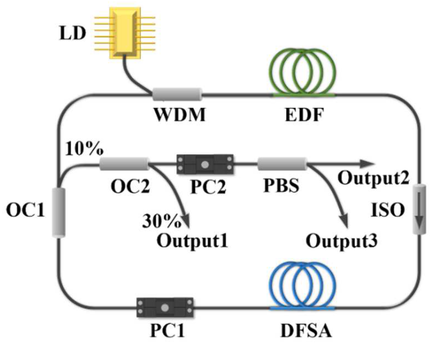
The structure diagram of a ring cavity mode-locked laser based on the DFSA is shown in Figure 1. The resonant cavity uses a 976 nm laser diode (LD) as the pump source, and the pump light is injected into the ring laser cavity through a 976/1550 nm wavelength division multiplexer (WDM). The gain medium is a 3 m Er-doped fiber (Coherent|Nufern, Santa Clara, CA, USA, SM-ESF 7/125). The PI-ISO ensures that the laser propagates in a single path within the cavity. DFSA is 0.9 m THDF (Coractive, Quebec City, QC, Canada, TH512, 8/125 μm), which is used as the SA in the cavity. In the gain fiber, when the light intensity is low, the dopant ions are in the ground state; thus, they can absorb a certain amount of light power and transform it into an excited state. However, when the light intensity increases, all the excited states of the dopant ions are filled, the absorption capacity of the gain fiber becomes saturated, and the light intensity cannot continue increasing; this is equivalent to the phenomenon of saturable absorption. PC1 is used to adjust the polarization state and birefringence inside the cavity. Subsequently, the output in the cavity is conducted via the OC1 (90:10). OC2, PC2, and PBS are used to study the polarization properties of output pulses. OC2 30% is used to output the initial pulse of the built laser, and the remaining 70% of the pulse is separated in two polarization directions using PBS. Thus, Output1, Output2, and Output3 can simultaneously detect the initial pulse and two orthogonal polarization components. The additional PC2 outside the cavity is used to balance the linear polarization state changes caused by the use of lead fibers outside the cavity. The total cavity length of the mode-locked laser is approximately 11 m. The cavity mainly consisted of a ~3 m EDF, a 0.9 m THDF, and a ~7.1 m SMF, whose group velocity dispersions are 58.94 ps2km−1, −55 ps2km−1, and −22 ps2km−1, which corresponds to an estimated net dispersion of 0.029 ps2. The laser performance is observed using an optical spectrum analyzer (Yokogawa, Sugar Land, TX, USA, AQ6370D) with a 0.02 nm resolution and a 12.5 GHz digital oscilloscope (Tektronix, Beaverton, OR, USA, DPO71254C) together with a 5 GHz photon detector (Thorlabs, Newton, NJ, USA, DET08CFC/M).

Figure 1.
Schematic of the EDFL. LD: laser diode; WDM: wavelength division multiplexer; EDF: Erbium-doped fiber; ISO: isolator; PC: polarization controller; OC: optical coupler; PBS: polarization beam splitter.
3. Experimental Results and Discussion
3.1. EDFL Based on THDF-SA
In the homemade ring-cavity fiber laser, a self-starting mode-locked state was easily achieved by adjusting the pump power, and the mode-locked threshold pump power was 165 mW. Figure 2a shows the bright mode-locked pulse sequence with a pulse spacing of 56 ns, corresponding to a repetition rate of 17.86 MHz and a cavity length of 11 m, thus indicating that the laser operates in a CW mode-locked state. The inset shows the unfolding of a mode-locked pulse train with a pulse width of about 120 ps. The pulse width, limited by the rise/fall time of photodetector, could not be accurately measured. RF spectrum is a key parameter that can confirm and characterize the stability of the pulse operation. Figure 2b shows the RF spectrum trace of the bright pulse; evidently, the signal-to-noise ratio (SNR) was 47 dB, thus indicating the relative stability of the mode-locked operation. The output spectrum is shown in Figure 2c, with a central wavelength of 1598.5 nm, and the 3-dB bandwidth is 0.24 nm. When the pump power continued to increase and the polarization controller was adjusted, a dark pulse appeared. Figure 2d shows the dark pulse sequence at a pump power of 550 mW, with a pulse interval of 56 ns, corresponding to a repetition rate of 17.86 MHz, the same as that of bright pulses. The SNR and repetition rate of the dark pulses were 52 dB and 17.86 MHz, respectively, as shown in Figure 2e. Notably, the SNR of the dark pulse was slightly higher than that of the bright pulse, which is consistent with the more stable transmission characteristics of the dark pulses in the laser. The corresponding spectrum is shown in Figure 2f, which exhibits a multipeak distribution within a certain range, a typical feature of DW-type dark pulses, where pulses of multiple wavelengths oscillate simultaneously in the cavity, thereby causing temporal topological defects [29]. Furthermore, to confirm that the mode-locked pulse is caused by the THDF-SA, extensive adjustments of the polarization state and pump power were performed in a cavity without the DFSA. No mode-locked pulse was observed, excluding the possibility of self-mode-locked and NPR mode-locked pulses.
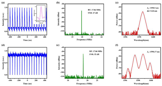
Figure 2.
(a) Bright pulse sequence (inset: pulse sequence expansion); (b) bright pulse RF spectrum trace; (c) bright pulse output spectrum; (d) dark pulse sequence; (e) dark pulse RF spectrum trace; (f) dark pulse output spectrum.
To further evaluate the stability of the bright pulse and dark pulse laser output, the lasing spectrum was scanned at 10-min intervals over a one-hour period, as depicted in Figure 3a,b. These results indicate that the mode-locked lasing output exhibited a high level of stability.
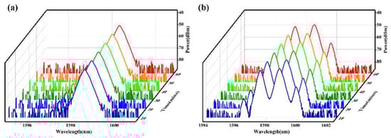
Figure 3.
(a,b) Stability test of the bright pulse and dark pulse.
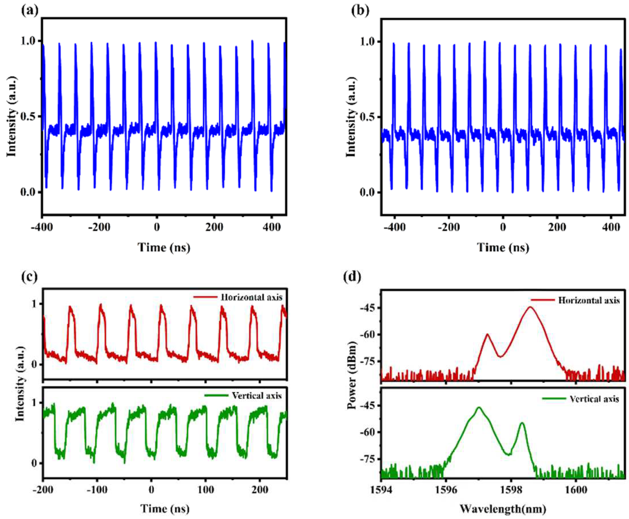
After careful adjustment of the polarization state inside the cavity, bright–dark pulse pairs and dark–bright pulse pairs were obtained, as shown in Figure 4a,b, with a pulse interval of 56 ns corresponding to a fundamental repetition rate of 17.86 MHz. This indicates that the obtained bright–dark and dark–bright pulse pairs were operating in the mode-locked state. In 1989, Afanasyeve [30] et al. demonstrated that strong repulsive interactions may exist between dark and bright pulses and proposed that cross-phase modulation has an important influence on the formation and interaction of pulses. Meanwhile, the bright and dark pulses were predicted to coexist. Research has shown that the generation of dark–bright pulse pairs is caused by cross-phase modulation and polarization effects inside the cavity. To investigate the polarization characteristics of the dark–bright pulse pairs, herein, a PBS was externally connected after OC1 to separate the pulse pairs sequence into two polarization directions [31]. In the experiment, two output pulses in perpendicular polarization directions were successfully detected on the oscilloscope, as shown in Figure 4c, thus proving that the bright and dark pulses exist in two different polarization directions and are orthogonal to each other. Figure 4d shows the corresponding spectrum, with the peak center wavelengths of the strong peaks being 1597.02 nm and 1598.6 nm, respectively. Evidently, the two spectra exhibited distinct differences in wavelength and distribution, thus indicating that the two polarization components are noncoherently coupled. As our filter was unsuitable, we could not filter accurately on the wavelength; however, based on the change in spectral intensity, we can speculate that the long and short wavelengths correspond to the bright and dark pulses, respectively. Additionally, DW-type dark pulses are formed by the oscillation of two or more wavelengths of pulses within the cavity, typically characterized by a spectrum with multiple peaks. Due to the gain competition effect among pulses of different wavelengths and intensities oscillating simultaneously within the cavity, the fiber laser ultimately operates in a dual-wavelength vector mode-locked state.

Figure 4.
(a) Bright–dark pulse pairs; (b) dark–bright pulse pairs; (c) pulse sequence after PBS; (d) output spectrum after PBS.
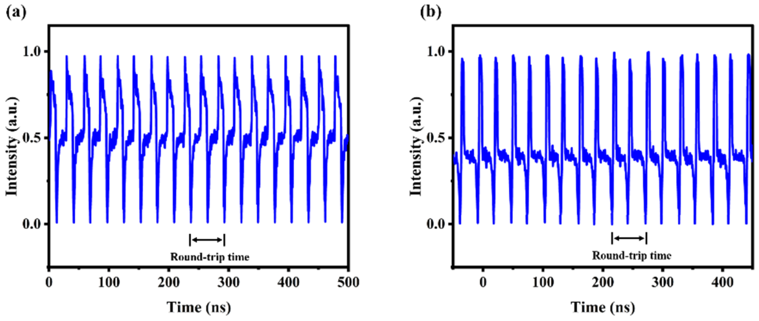
Subsequently, appropriate polarization modulation and gain modulation were performed, and some phenomena were observed in the experiment at a pump power of 550 mW. Figure 5a,b shows a sequence of second-order harmonic bright–dark pulse pairs and second-order harmonic dark–bright pulse pairs, where two pulses can be observed simultaneously within the 56 ns round-trip time of the cavity. The corresponding repetition rate at this time is 35.71 MHz. In this process, the formation of harmonic pulses was due to the increase in pump power and the inherent instability pulse caused by cross-phase modulation splitting. The new pulses slowly moved toward the other pulses in the cavity, eventually forming a harmonic.

Figure 5.
Harmonic mode-locked state: (a) second-order harmonic dark–bright pulse sequence; (b) second-order harmonic bright–dark pulse sequence.
3.2. EDFL Based on YDF-SA and EDF-SA
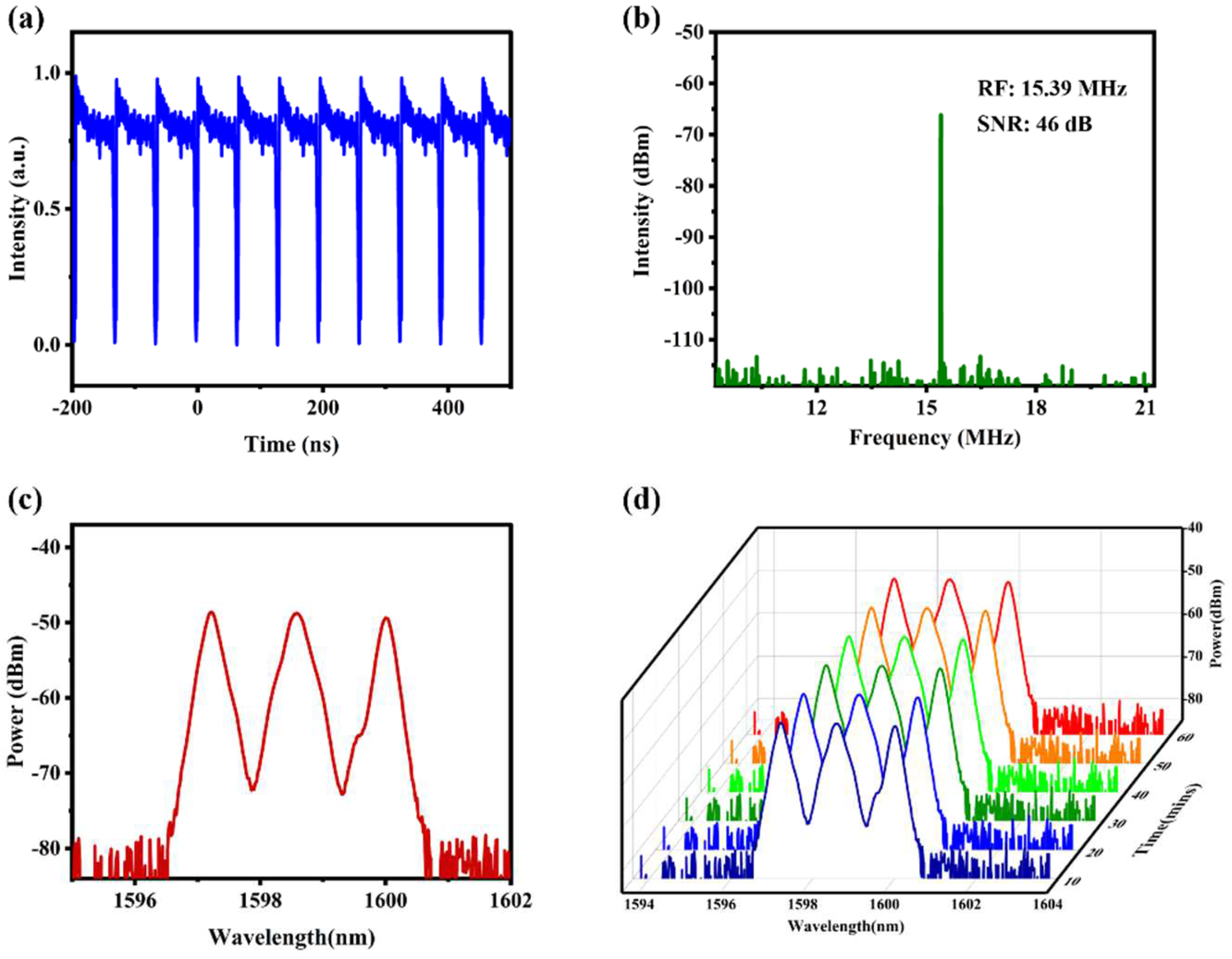
We successfully demonstrated the excellent performance of THDF as a saturable absorber in fiber lasers. Additionally, we attempted to use other doped fibers as the SA in an EDFL by replacing the 0.9 m THDF with 1.4 m YDF (Nufern, SM-YSF-HI-HP, 6/125 μm) and 1.4 m EDF (Nufern, SM-ESF-7/125, 7/125 μm), respectively, while keeping the other parameters the same. Furthermore, we successfully achieved the self-starting of the fiber laser through polarization and gain modulation. The appearance of dark pulses was observed in the EDFL based on EDF-SA, and the pulse sequences are shown in Figure 6a, exhibiting a pulse interval of 64.9 ns, corresponding to a fundamental repetition rate of 15.39 MHz, thus indicating that the laser was operating in a mode-locked state. The RF spectrum of the mode-locked pulse was also measured, as shown in Figure 6b, with SNRs of 46 dB, thus demonstrating the stability of the output mode-locked pulse. The output spectrum of dark pulses with a central wavelength of 1597.22, 1598.58, and 1600.00 nm is shown in Figure 6c, which is consistent with the typical distribution of multiple peaks in the frequency domain for DW-type dark pulses. The stability of the dual-wavelength lasing output was evaluated by periodically scanning the lasing spectrum with a 10-min interval in a one-hour period at room temperature. The findings are displayed in Figure 6d. We observed that the number of wavelengths of the dark pulses differs from the result based on THDF-SA. This discrepancy is likely related to the gain spectrum characteristics of THDF and EDF. The THDF has a broader gain bandwidth, covering a range from approximately 1.45 µm to 1.65 µm, whereas EDF’s gain bandwidth is relatively narrower, primarily centered around 1.5 µm. Therefore, the THDF-SA system may support pulse oscillations with a larger range of central wavelengths, leading to multiple-central-wavelengths lasing output. In the THDF-SA system, due to the broad gain spectrum and strong nonlinear effects, pulses at different wavelengths can interact through nonlinear processes such as four-wave mixing (FWM) and cross-phase modulation (XPM), further enhancing the stability of multi-wavelength dark pulses. In contrast, the narrower gain spectrum and weaker nonlinear effects in the EDF-SA system limit such interactions. Additionally, during the experiment, we observed that only the segment of EDF near the WDM exhibited the fluorescence effect, while the segment connected into the cavity as the SA showed no such phenomena. Therefore, we can rule out the possibility that the new segment of doped fiber functioned as a gain fiber within the cavity.
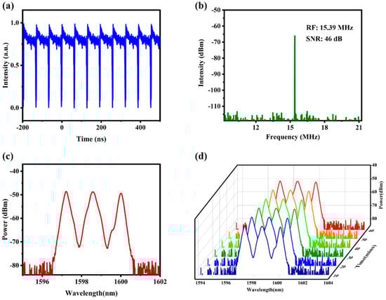
Figure 6.
Characteristics of the EDFL based on EDF-SA; (a) dark pulse sequence; (b) RF spectrum trace; (c) dark pulse spectrum; (d) stability test of the dark pulse lasing outputs.
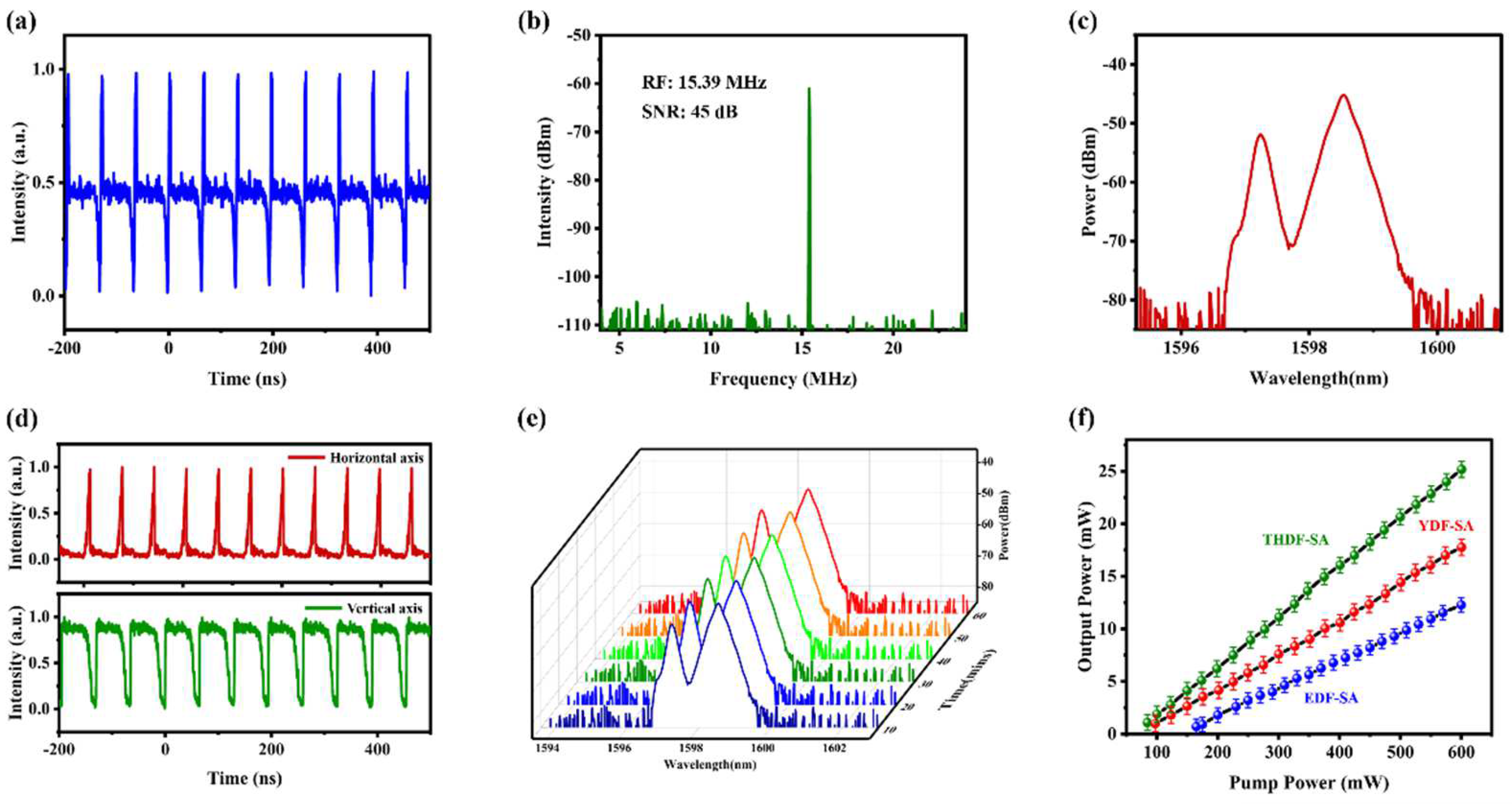
By using YDF-SA, dark pulse and dark–bright pulse outputs were obtained which were similar to the above results, and in Figure 7a, the pulse sequence of the dark–bright pulse outputs is demonstrated with a pulse interval of ~65 ns, corresponding to a repetition rate of 15.39 MHz and a cavity length of 13 m, thus indicating that the laser operates in a mode-locked state. Figure 7b,c shows the corresponding RF spectrum trace and pulse output spectrum, respectively. At a repetition rate of 15.39 MHz, the signal-to-noise ratio is 45 dB. It is noteworthy that the center wavelength of all the mode-locked pulses we obtained is around 1600 nm, whereas the emission peak of EDF is typically around 1550 nm. Franco et al. [32] used numerical simulations to propose that the wavelength of the laser emission is related to the cavity loss or the length of the gain fiber and the dopant ion concentration. Their study indicates that when certain laser parameter changes cause the gain in the 1.6 μm region to exceed that in the 1.5 μm region, the central wavelength of the laser output pulse shifts towards 1.6 μm. In addition, we verified the polarization properties of the dark–bright pulse sequence, as shown in Figure 7d, and found them to be similar to the output results of the THDF-SA-based laser, with dark and bright pulses existing in two orthogonal polarization directions. The stability test is shown in Figure 7e. Studies have shown [33,34] that when the output pulses are filtered using corresponding wavelength filters, the long wavelengths in the frequency domain correspond to bright pulses in the time domain, while short wavelengths correspond to dark pulses. Unfortunately, due to experimental limitations, we currently do not have the appropriate wavelength filters to verify this phenomenon.

Figure 7.
Characteristics of the EDFL based on YDF-SA: (a) dark–bright pulse sequence; (b) RF spectrum trace; (c) pulse output spectrum; (d) pulse sequence of the resolved beams along the two orthogonal polarization directions; (e) stability test of the dual-wavelength lasing outputs; (f) laser output power as a function of the pump power.
Evidently, the output power increases linearly with the pump power, as shown in Figure 7f. In particular, the output power of the THDF-based EDFL is higher than that of the EDF-based EDFL and YDF-based EDFL. This is because the absorption efficiency of EDF is higher than that of THDF and YDF near the 1550 nm band, which we speculate may result in a smaller variety of output pulse types obtained by the EDF-based EDFL, possibly owing to its higher losses. The possibility of obtaining a higher output power was limited by the maximum pump power of 600 mW in this study.
4. Conclusions
We demonstrated a passive mode-locked EDFL based on a DFSA with three experiments using THDF, YDF, and EDF. This represents the first application of these three types of gain fibers in a bright–dark pulse mode-locked EDFL. In the experiment based on THDF-SA, four output states were observed, including bright pulse, dark pulse, bright–dark pulse pairs, and dark–bright pulse pairs, all with a pulse interval of 56 ns. At the fundamental repetition rate of 17.86 MHz, all SNRs exceeded 45 dB, demonstrating good stability. The orthogonal characteristics of the dark–bright pulse pairs were verified by connecting a PBS outside the cavity. In the experiment based on EDF-SA and YDF-SA, dark pulses and dark–bright pulse sequences were observed, respectively, with a pulse interval and repetition rate of 64.9 ns and 15.39 MHz, respectively, and all the SNRs exceeded 45 dB. We confirmed that the dark–bright pulse sequence had the same orthogonal characteristics. Additionally, the output powers of the three experiments were compared, and the output power of the EDFL based on THDF-SA was slightly higher than the others, whereas the mode-locked threshold was lower. Passive mode-locked Er-doped fiber lasers based on DFSA have the advantages of simple structure and ease of preparation and debugging, and they offer broad application prospects in ultrashort pulse lasers.
Author Contributions
Conceptualization, Y.Q. and Q.Y.; methodology, Q.Y.; software, Y.G.; validation, Y.Z.; formal analysis, Z.B. and J.D.; resources, B.Y.; writing—review and editing, Y.W.; supervision, D.Y.; project administration, Z.L.; funding acquisition, W.S. All authors have read and agreed to the published version of the manuscript.
Funding
This work was supported by the National key research and development program (2021YFB2900700), the Key projects of Jiangsu Province’s key research and development program (BE2022055), the National Natural Science Foundation of China (62375075), the Natural Science Foundation of Hebei Province (F2022202036), and the China Postdoctoral Science Foundation under Grant (2022M712485).
Institutional Review Board Statement
Not applicable.
Informed Consent Statement
Not applicable.
Data Availability Statement
Data is unavailable due to privacy or ethical restrictions.
Conflicts of Interest
The authors declare no conflicts of interest.
References
- Oe, R.; Taue, S.; Minamikawa, T.; Nagai, K.; Shibuya, K.; Mizuno, T.; Yamagiwa, M.; Mizutani, Y.; Yamamoto, H.; Iwata, T.; et al. Refractive-index-sensing optical comb based on photonic radio-frequency conversion with intracavity multi-mode interference fiber sensor. Opt. Express 2018, 26, 19694–19706. [Google Scholar] [CrossRef] [PubMed]
- Li, L.; Lv, R.; Liu, S.; Yan, P.; Wang, Y.; Ren, W.; Wang, J.; Chen, Z. Nonlinear optical response and application of WS2 saturable absorber. Laser Phys. Lett. 2018, 15, 115102. [Google Scholar] [CrossRef]
- Gabel, C.V. Femtosecond lasers in biology: Nanoscale surgery with ultrafast optics. Contemp. Phys. 2008, 49, 391–411. [Google Scholar] [CrossRef]
- Sugioka, K.; Cheng, Y.; Midorikawa, K. Three-dimensional micromachining of glass using femtosecond laser for lab-on-a-chip device manufacture. Appl. Phys. A 2005, 81, 1–10. [Google Scholar] [CrossRef]
- Kehayas, E.; Stampoulidis, L.; Henderson, P.; Robertson, A.; Van Dijk, F.; Achouche, M.; Le Kernec, A.; Sotom, M.; Schuberts, F.; Brabant, T. The European project HIPPO high-power photonics for satellite laser communications and on-board optical pro-cessing. In Proceedings of the International Conference on Space Optics—ICSO 2014, Tenerife, Spain, 6–10 October 2014; SPIE: Bellingham, WA, USA, 2017; pp. 1527–1532. [Google Scholar]
- Dolfi-Bouteyre, A.; Canat, G.; Valla, M.; Augere, B.; Besson, C.; Goular, D.; Lombard, L.; Cariou, J.; Durecu, A.; Fleury, D. Pulsed 1.5 μm LIDAR for axial aircraft wake vortex detection based on high-brightness large-core fiber amplifier. IEEE J. Sel. Top. Quantum Electron. 2009, 15, 441–450. [Google Scholar] [CrossRef]
- Yang, S.; Zhang, Q.-Y.; Zhu, Z.-W.; Qi, Y.-Y.; Yin, P.; Ge, Y.-Q.; Li, L.; Jin, L.; Zhang, L.; Zhang, H. Recent advances and challenges on dark solitons in fiber lasers. Opt. Laser Technol. 2022, 152, 108116. [Google Scholar] [CrossRef]
- Zakharov, V.; Shabat, A. Interaction between solitons in a stable medium. Sov. Phys. JETP 1973, 37, 823–828. [Google Scholar]
- Saarloos, W.; Hohenberg, P. Fronts, pulses, sources and sinks in generalized complex Ginzburg-Landau equations. Phys. D Nonlinear Phenom. 1992, 56, 303–367. [Google Scholar] [CrossRef]
- Bekki, N.; Nozaki, K. Formations of spatial patterns and holes in the generalized Ginzburg-Landau equation. Phys. Lett. A 1985, 110, 133–135. [Google Scholar] [CrossRef]
- Tiu, Z.C.; Suthaskumar, M.; Zarei, A.; Tan, S.J.; Ahmad, H.; Harun, S.W. Generation of switchable domain wall and cubic–quintic nonlinear Schrödinger equation dark pulse. Opt. Laser Technol. 2015, 73, 127–129. [Google Scholar] [CrossRef]
- Zhang, H.; Tang, D.Y.; Zhao, L.M.; Knize, R.J. Vector dark domain wall solitons in a fiber ring laser. Opt. Express 2010, 18, 4428–4433. [Google Scholar] [CrossRef] [PubMed]
- Zian, C.T.; Arman, Z.; Sin, J.T.; Harith, A.; Sulaiman, W.H. Harmonic dark pulse emission in erbium-doped fiber laser. Chin. Phys. Lett. 2015, 32, 034203. [Google Scholar] [CrossRef]
- Tang, D.Y.; Li, L.; Song, Y.F.; Zhao, L.M.; Zhang, H.; Shen, D.Y. Evidence of dark solitons in all-normal-dispersion-fiber lasers. Phys. Rev. A 2013, 88, 013849. [Google Scholar] [CrossRef]
- Fermann, M.E.; Hartl, I. Ultrafast Fiber Laser Technology. IEEE J. Sel. Top. Quantum Electron. 2009, 15, 191–206. [Google Scholar] [CrossRef]
- Qi, Y.; Yang, S.; Wang, J.; Li, L.; Bai, Z.; Wang, Y.; Lv, Z. Recent advance of emerging low-dimensional materials for vector soliton generation in fiber lasers. Mater. Today Phys. 2022, 23, 100622. [Google Scholar] [CrossRef]
- Wang, M.; Huang, Y.; Song, Z.; Wei, J.; Pei, J.; Ruan, S. Two-micron all-fiberized passively mode-locked fiber lasers with high-energy nanosecond pulse. High Power Laser Sci. Eng. 2020, 8, e14. [Google Scholar] [CrossRef]
- Gene, J.; Yeom, D.-I.; Kim, S.K.; Lim, S.D. Long-cavity mode-locked thulium-doped fiber laser for high pulse energy. Opt. Laser Technol. 2020, 136, 106739. [Google Scholar] [CrossRef]
- Yu, Q.; Qi, Y.; Bai, Z.; Ding, J.; Yan, B.; Wang, Y.; Lu, Z.; Yan, D. L-band of ~1.6 μm tunable multi-wavelength mode-locked Er-doped fiber laser with an MMF- FMF based structure. Opt. Fiber Technol. 2024, 84, 103762. [Google Scholar] [CrossRef]
- Yu, Q.; Liu, M.; Qi, Y.; Luan, N.; Bai, Z.; Ding, J.; Yan, B.; Wang, Y.; Lu, Z. Tunable Single and Multi-Wavelength Er-Doped Mode-Locked Fiber Laser Based on GIMF-PCF-GIMF. IEEE Photon-Technol. Lett. 2023, 35, 1043–1046. [Google Scholar] [CrossRef]
- Shang, J.; Feng, J.; Li, T.; Feng, T.; Liu, Y.; Zhao, S.; Zhao, Y.; Song, Y. A Watt-level noise-like Tm-doped fiber oscillator by nonlinear polarization rotation. Appl. Phys. Express 2021, 14, 052001. [Google Scholar] [CrossRef]
- Lu, Y.; Gu, X. All-fiber passively Q-switched fiber laser with a Sm-doped fiber saturable absorber. Opt. Express 2013, 21, 1997–2002. [Google Scholar] [CrossRef] [PubMed]
- Lu, Y.; Gu, X. Kilowatt peak power pulses from a passively Q-switched Yb-doped fiber laser with a smaller-core Yb-doped fiber as a saturable absorber. IEEE Photon-J. 2014, 6, 1–7. [Google Scholar] [CrossRef]
- Tao, M.; Wu, J.; Peng, J.; Wu, Y.; Yang, P.; Ye, X. Experimental demonstration of an Er-doped fiber ring laser mode-locked with a Tm–Ho co-doped fiber saturable absorber. Laser Phys. 2013, 23, 085102. [Google Scholar] [CrossRef]
- Latiff, A.; Kadir, N.; Ismail, E.; Shamsuddin, H.; Ahmad, H.; Harun, S. All-fiber dual-wavelength Q-switched and mode-locked EDFL by SMF-THDF-SMF structure as a saturable absorber. Opt. Commun. 2017, 389, 29–34. [Google Scholar] [CrossRef]
- Zhang, P.; Nizamani, B.; Najm, M.M.; Dimyati, K.; Yasin, M.; Harun, S.W. Self-starting triple-wavelength vector dark soliton with a bismuth-doped fiber saturable absorber. Opt. Lett. 2021, 46, 3336–3339. [Google Scholar] [CrossRef] [PubMed]
- Zhang, P.; Dimyati, K.; Nizamani, B.; Najm, M.M.; Yasin, M.; Harun, S.W. Ultrashort pulse generation in All-fiber Er-bium-doped fiber cavity with thulium doped fiber saturable absorber. Opt. Laser Technol. 2022, 149, 107888. [Google Scholar] [CrossRef]
- Zhang, W.; Zheng, L.; Jiang, H.; Liu, N.; Yang, K.; Xian, T.; Zhan, L. Bright-Dark Pulse Pair in a Passively Mode-Locked Fiber Laser Based on Thulium-Doped Fiber. IEEE Photonics Technol. Lett. 2024, 36, 429–432. [Google Scholar] [CrossRef]
- Yang, S.; Zhang, Q.-Y.; Li, L.; Jin, L.; Chen, S.-C. Generation of dark solitons in a self-mode-locked Tm-Ho doped fiber laser. Infrared Phys. Technol. 2022, 121, 104043. [Google Scholar] [CrossRef]
- Afanasyev, V.V.; Kivshar, Y.S.; Konotop, V.V.; Serkin, V.N. Dynamics of coupled dark and bright optical solitons. Opt. Lett. 1989, 14, 805–807. [Google Scholar] [CrossRef]
- Zhu, Z.; Yang, S.; He, C.; Lin, X. Vector pure-quartic soliton molecule fiber laser. Chaos Solitons Fractals 2023, 175, 113978. [Google Scholar] [CrossRef]
- Franco, P.; Midrio, M.; Tozzato, A.; Romagnoli, M.; Fontana, F. Characterization and optimization criteria for filterless erbium-doped fiber lasers. J. Opt. Soc. Am. B 1994, 11, 1090–1097. [Google Scholar] [CrossRef]
- Wu, Q.; Wu, Z.; Yao, Y.; Xu, X.; Chen, L.; Zhao, Y.; Xu, K. Three-component bright–dark–bright vector pulse fiber laser basedonMoS2 saturable absorber. Opt. Commun. 2021, 498, 127231. [Google Scholar] [CrossRef]
- Nady, A.; Semaan, G.; Kemel, M.; Salhi, M.; Sanchez, F. Polarization-color domain walls in fiber ring lasers. J. Light. Technol. 2020, 38, 6905–6910. [Google Scholar] [CrossRef]


Disclaimer/Publisher’s Note: The statements, opinions and data contained in all publications are solely those of the individual author(s) and contributor(s) and not of MDPI and/or the editor(s). MDPI and/or the editor(s) disclaim responsibility for any injury to people or property resulting from any ideas, methods, instructions or products referred to in the content. |
© 2024 by the authors. Licensee MDPI, Basel, Switzerland. This article is an open access article distributed under the terms and conditions of the Creative Commons Attribution (CC BY) license (https://creativecommons.org/licenses/by/4.0/).