1. Introduction
As the scarcity of spectrum resources in traditional radio frequency (RF) communication methods approaches critical levels [
1], researchers and engineers are increasingly turning their attention to optical wireless communication (OWC) technologies. Among the various categories of OWC, visible light communication (VLC) stands out due to its advantages, such as no spectrum license being required, minimal interference, high security, low system complexity, low cost, high data transmission rates, and a wide range of potential applications [
2]. Additionally, VLC can simultaneously perform illumination and data transmission, making it a promising complement to traditional wireless local area network WLAN technology [
3]. Within the various applications derived from VLC, visible light positioning (VLP) technology shows considerable potential for development. Compared with traditional RF-based positioning technologies, VLP provides several advantages, including higher spatial resolution due to the excellent directionality of visible light, which allows for centimeter-level accuracy in confined spaces [
4]. Additionally, VLP’s compatibility with existing LED lighting infrastructure and power line communication (PLC) technologies simplifies its deployment [
5]. As Internet of Things (IoT) technologies and the sixth generation of wireless communication networks (6G) continue to evolve, standalone VLC and VLP systems struggle to meet the fundamental requirements for the simultaneous communication and positioning functions of emerging IoT devices such as robotic vacuum cleaners, smart streetlights, wireless underwater exploration equipment, etc. Therefore, developing systems that integrate both VLC and VLP capabilities, i.e., visible light communication and positioning (VLCP), is crucial for advancing the development of 6G IoT.
Previous studies have proposed various design strategies for VLCP systems tailored to different application scenarios. For example, in terms of channel reuse, Yu‘s group proposed a multi-user simultaneous indoor VLCP system scheme and solutions based on channel optimization and frame structure design [
6,
7]; in terms of underwater applications, Fu’s group proposed a full-duplex VLCP solution for underwater wireless sensor networks [
8]; Shao et al. relied on backscatter communication in the RF field to propose a retroreflective-VLCP scheme in the optical domain [
9]; and Yang et al. proposed a VLCP system design for modulation technology optimization based on filter bank multicarrier [
10]. In all of these VLCP systems, photodiodes (PDs) serve as receivers to capture the light signals and convert them into a photocurrent proportional to the received light power. Nevertheless, a major drawback of using PDs as receivers is their need for external power to support the conversion from photocurrent to voltage and to maintain the PDs at their ideal operating point, which limits the independent operation ability and the miniaturization of the receivers. This limitation is disadvantageous for the deployment of devices in various IoT applications, such as smart homes and smart factories, and restricts their use in energy-constrained environments like underwater and storage tanks.
To address the above issue, research into integrating photovoltaic (PV) technology into indoor VLCP could be highly beneficial. Several studies have verified the feasibility of using solar cells (SCs) to replace photodiodes (PDs) in VLC systems for simultaneous data and energy reception [
11,
12,
13], introducing the concept of simultaneous lightwave information and power transfer (SLIPT) [
14]. A vital advantage of this concept is that solar cells, as passive devices, do not require external power to achieve photovoltaic conversion, thereby enabling self-powered operation [
15]. Additionally, compared with PDs, which typically have a few square millimeters of effective receiving area, solar cells generally feature a much larger effective receiving area, ranging from several tens to hundreds of square centimeters. This larger area not only provides a broader receiving angle but also helps mitigate issues like partial fading. However, most research into SLIPT in the VLC domain primarily focuses on enhancing transmission rates [
16,
17], often using laser light sources [
18,
19]. As for the field of indoor VLP, studies integrating it with PV technology remain scarce. To date, only Hsu et al. have proposed a positioning system using PV as the receiver, which accomplishes positioning relative to three LED sources through identity positioning and radio frequency carrier allocation, without discussing the system’s communication capabilities [
20]. This does not address the challenges faced by VLCP system receivers in environments with limited light sources and energy supplies, such as underwater, unmanned storage, and unmanned factories, where synchronous communication and positioning are required. In this context, studies of indoor VLCP systems and algorithms based on PV receivers represent a promising and largely unexplored research direction within the VLCP field.
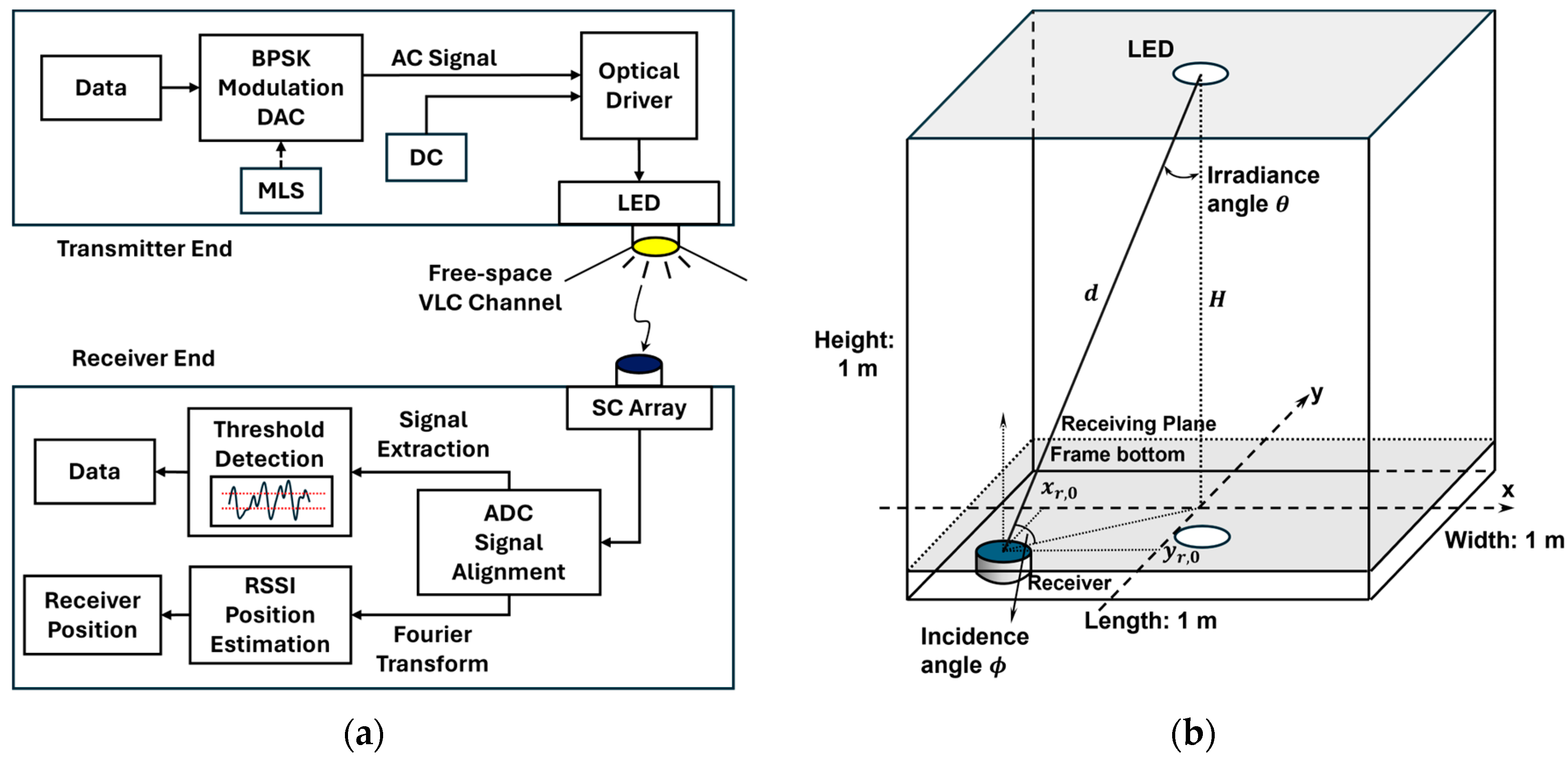
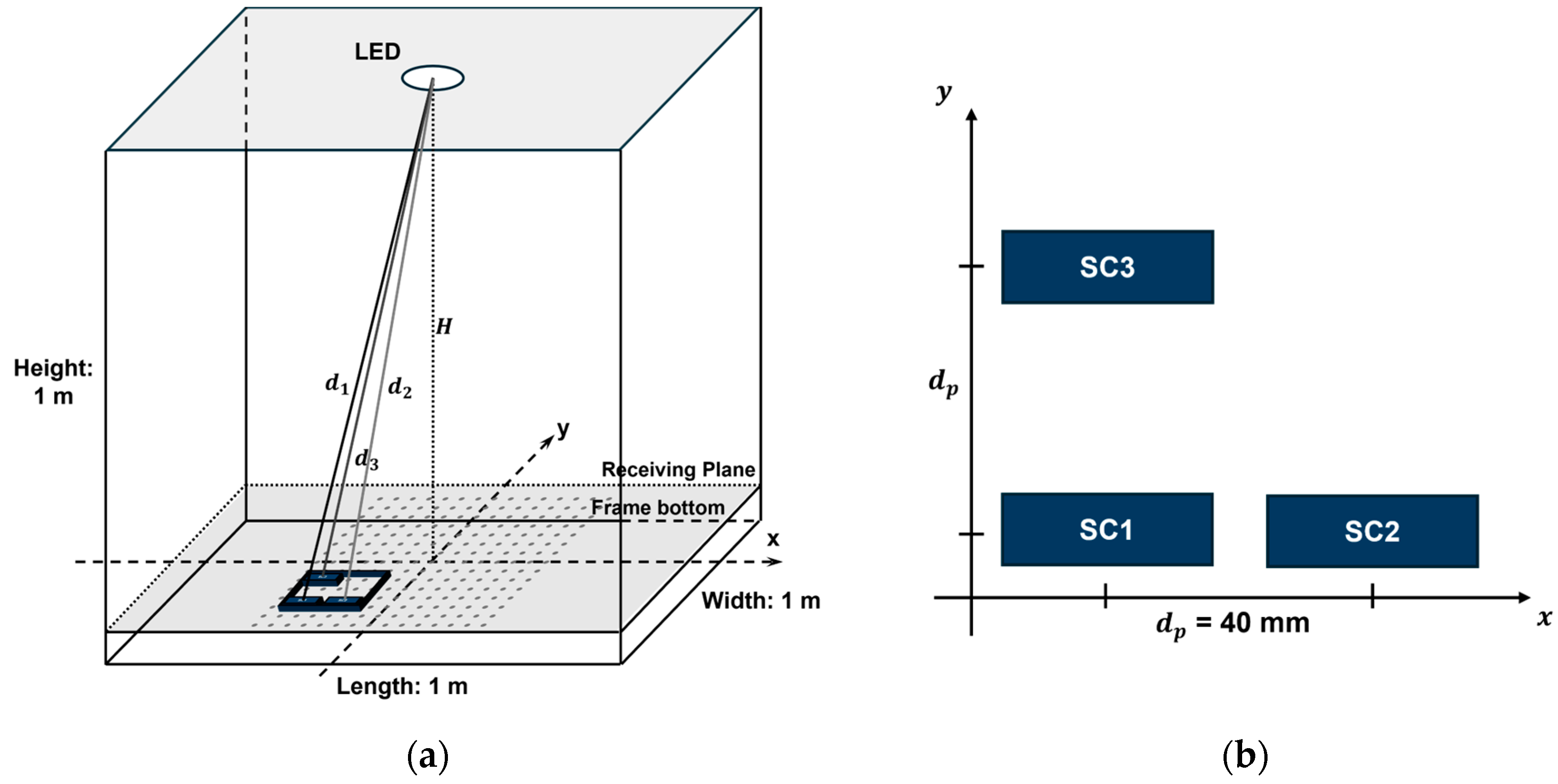
In this paper, we propose an indoor VLCP system utilizing one LED transmitter and an array of multiple SC receivers, alongside a right-angled tetrahedron trilateration VLP (RATT-VLP) algorithm. The system achieves VLC through the modulation and demodulation of BPSK signals. Concurrently, using the received signal’s strength (RSS) extracted from the demodulation process as an indicator, the signal transmission distances between the LED and the receivers can be determined, given the known coordinates of the LED and the relative positions of the SC receivers. Then, the position of the devices is ascertained through the RATT-VLP algorithm based on the LED’s coordinate, the configuration of the receivers, and signal transmission distances, thereby facilitating VLP. By only employing one transmitter, our system offers deployment flexibility under limited light source conditions. Our experimental results demonstrate that this system can simultaneously perform signal transmission and receiver positioning, showcasing the feasibility of applying SCs to indoor VLCP systems and the potential for implementing SLIPT in such systems.
3. Results and Discussion
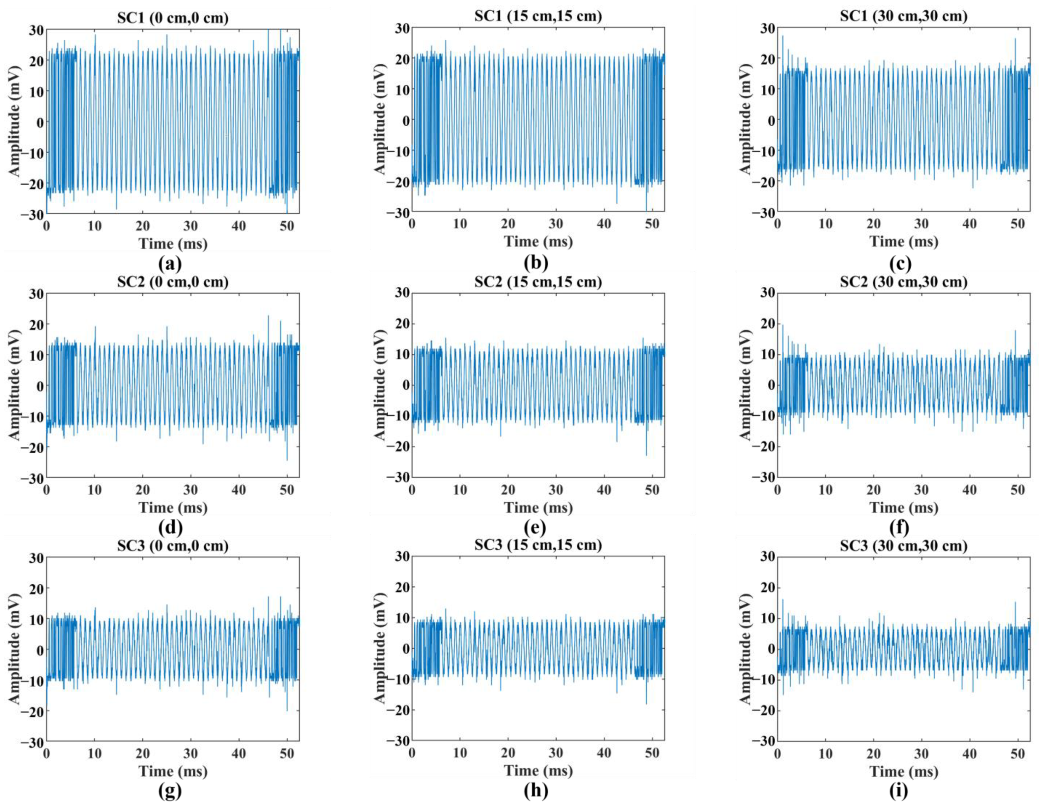
Figure 4 shows the downsampled sinusoidal waveforms received by SC1, SC2, and SC3 at three selected points on the diagonal of the receiving plane: point A (0 cm, 0 cm), point B (15 cm, 15 cm), and point C (25 cm, 25 cm). The received sine signals are downsampled according to the ratio of the sampling rates of the oscilloscope (OSC) and the arbitrary waveform generator (AWG), and their AC components are extracted. The waveforms at each point, as illustrated in the figure, contain noise and exhibit amplitude variations across different points. These will be processed later to ascertain specific signal strengths. Furthermore,
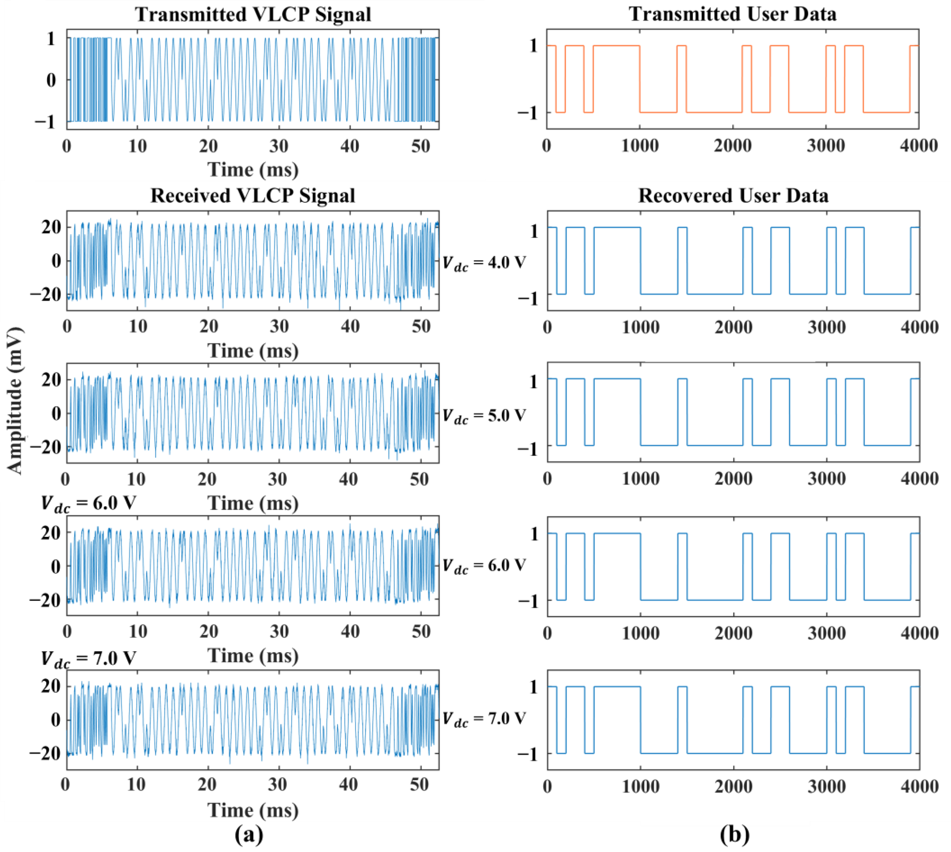
Figure 5 showcases the waveforms of the BPSK signals received at point A under varying LED DC drive voltages, alongside the results of their demodulation and a comparison with the original data. All waveforms were successfully demodulated without errors, achieving a maximum data rate of 1.21 kbps. This data rate demonstrates that this SC-based VLCP system possesses adequate capabilities for supporting common low-speed VLC schemes, which may include applications where high-data-rate transmission is not critical, such as in sensor networks, smart lighting systems, or basic indoor positioning systems with lower polling rates.
By performing a Fourier transform on the extracted signals collected from various points on the receiving surface, the corresponding signal strength was calculated. This method facilitated the estimation of the RSS distributions across the receiving plane for the three SCs, as illustrated in
Figure 6. The RSS distributions for all three SCs exhibited a clear pattern, with lower values around the periphery than at the center. Additionally, the maximum RSS values for SC2 and SC3 were observed to shift toward the negative x-axis and negative y-axis, respectively. These shifts can be attributed to the L-shaped arrangement of the SCs, with SC2 positioned along the positive x-axis and SC3 along the positive y-axis. The experimental results were consistent with expectations and correctly reflected the spatial orientation of the SCs within the receiver.
After estimating the RSS for each SC channel, we applied a fitting method to derive a set of fitting functions based on Equation (9). The regression curves, representing the transmission distances between the LED and each corresponding SC, exhibited clear exponential decay. The derived fitting functions for estimating the transmission distance,
from the
-th SC’s RSS,
are as follows:
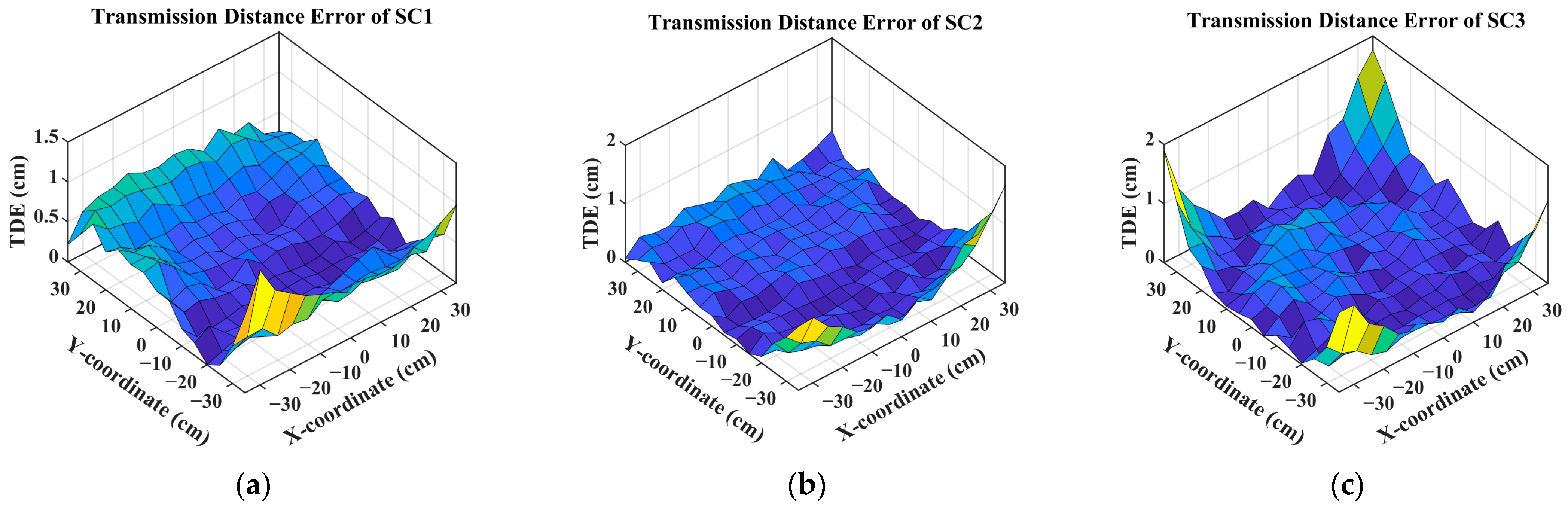
To accurately quantify the precision of the transmission distance estimates within our system, we utilized the transmission distance error (TDE) metric, which measures the absolute difference between the estimated and theoretical transmission distances. The distributions of TDE are shown in
Figure 7, illustrating a clear trend: the TDE increases as the distance from the center increases. This observed pattern indicates that the accuracy of the VLP system diminishes as the distance increases, likely due to factors such as signal attenuation and environmental interference.
By using Equation (11), we calculated the estimated positions of the test points, and the positioning results are displayed in
Figure 8a. To enhance clarity in the diagram, only the central 11 × 11 points are retained, as more significant deviations were observed at the periphery points. In the figure, blue dots represent the theoretical positions of the test points, while red stars indicate the estimated positions. Lines connecting these points help visually illustrate the degree of positioning deviation.
From the figure, it is evident that within the central 7 × 7 points, covering a 30 cm × 30 cm area, the deviation between the estimated positions and the theoretical positions is relatively small. We conducted a statistical analysis of the positioning errors for the central 7 × 7 points, the central 11 × 11 points, and all 15 × 15 points, with the results shown in
Figure 8b. For the 7 × 7 points, the positioning errors are well concentrated within 5 cm, with an average error of 3.40 cm. For the larger area of 11 × 11 points, most positioning errors are less than 10 cm. However, for all test points, the average error is 10.49 cm. The box plot shows that the median lines of the three groups of statistical data are all lower than the mean values. Additionally, as more peripheral points are included, this skewness gradually increases. This indicates that the positioning errors of the peripheral points significantly raise the overall positioning error, while the errors of the central points remain low.
Figure 8c shows the cumulative number of points that are less than the corresponding positioning error; out of the total 225 test points in the experiment, 82 points had positioning errors of less than 5 cm, and over 140 points had errors of less than 10 cm. As the positioning error increases, the increment in the number of points gradually decreases, supporting the above observations. Overall, the VLCP system demonstrated good positioning accuracy.
As the positioning area increases, the discrepancy between the theoretical and estimated positions begins to increase significantly. Given the comprehensive consideration of previous results, this could be attributed to several factors. Firstly, the SCs used may have a poor low-light response, making it challenging to distinguish RSS accurately at the periphery, where the light intensity is relatively lower than the central area. Secondly, the undefined far-field light intensity distribution of the LED used in the experiments might contribute to the errors, especially if the LED has a narrow viewing half-angle, leading to a rapid decline in RSS measurements beyond the 50 cm × 50 cm area. Additionally, noise introduced by the receiver’s peripheral circuitry could also be a contributing factor to these errors.
Lastly, we compared the results of this work with previous PD/SC-based VLC/VLP methods, as shown in
Table 1. As the first single-source SC-VLCP, our work is unique in simultaneously achieving visible light communication and positioning using a solar cell. The VLC system in [
12] is based on an α-Si SC panel, achieving a rate of 11.84 Mbps by applying OFDM, but it does not have VLP capability. This work can provide a reference for us to apply more advanced modulation techniques in the future. Refs. [
10,
24] present common multi-source VLP systems based on PD and APD, respectively. Compared with these, our work still lags slightly behind in overall positioning accuracy compared with PD-based methods, though it achieves comparable accuracy in narrow-range positioning. This also provides data for future optimization efforts.
4. Future Work
Throughout this study, the feasibility of using SC as a VLCP receiver has been validated, achieving an initiative simultaneous SC-VLCP system with vast potential for applications in light-source-limited scenarios. Based on our work, it is believed that various derivative directions merit further investigation, including but not limited to channel model investigation; hardware optimization of SC receivers; and the integration of visible light communication, positioning, and energy harvesting within the SLIPT framework.
For channel model investigation, future research could include the further simulation of channel models that include NLoS components, particularly in SC-based VLCP systems. Advanced simulation techniques could be employed to model channel behavior under various reflection conditions, and practical experiments could be conducted that include complex indoor environmental factors [
25]. This will help evaluate and quantify the overall impact of NLoS propagation on system communication performance and positioning accuracy. These steps are crucial for optimizing system design, enhancing the robustness of positioning algorithms, and advancing the application of SC-VLCP technology in real-world complex environments.
For hardware optimization, a well-designed receiver circuit could help obtain high-quality VLCP signals. Future work could involve optimizing the circuit design of the SC array receiving module to reduce the impact of circuit noise on the received signal, including implementing stricter power supply noise shielding and applying advanced filtering circuits. Applying nonlinear compensation circuits for SC under low illumination may also help improve the overall performance of the system [
26].
For energy harvesting, the efficiency of solar cells and optimization strategies within the SLIPT framework could be key focus areas for future research. The next steps of this work could involve discussing and verifying methods to improve the energy harvesting efficiency of SC receivers and achieve self-powered receivers, enabling the simultaneous implementation of visible light communication, positioning, and energy harvesting. Emerging solar cells with novel structures and materials could be applied to achieve significant improvements in rate and power conversion efficiency [
27]. Signal modulation and demodulation techniques could also be optimized, and efficient resource allocation strategies are worth studying to enhance the applicability of SC-VLCP systems. These advancements will help fully optimize and extend the application of SLIPT in VLCP systems.
5. Conclusions
This paper proposed a solar-cell-array-based indoor VLCP system with a single LED transmitter, coupled with the RATT-VLP algorithm based on multiple SC receivers. The LED emits VLCP signals that pass through the VLC channel and are captured by the SC array, serving dual purposes for communication and positioning. The alignment of the received BPSK signals is achieved through autocorrelation with an MLS, and the data are demodulated using threshold judgment. The RSS calculations employ the Fourier transform method, and the receiver position is determined using RATT-VLP. Experimental validation confirmed the feasibility of the proposed VLCP system and the RATT-VLP algorithm. For BPSK-modulated signals, the highest measured VLC communication data rate for this VLCP system was 1.21 kbps, demonstrating its ability to support low-speed VLC applications. Furthermore, the RATT-VLP algorithm applied within this VLCP system achieved an average positioning accuracy of 3.40 cm within a 30 cm × 30 cm area, with an overall average accuracy of 10.49 cm. The results showcase the SC array-based indoor VLCP system’s potential for implementing communication and positioning functions simultaneously. Finally, future research directions based on this work are provided, including but not limited to channel model investigation, SC receiver hardware and circuitry optimization, and energy harvesting efficiency improvement for achieving SC-VLCP systems under the SLIPT concept.


