Article

Single-Source VLCP System Based on Solar Cell Array Receiver and Right-Angled Tetrahedron Trilateration VLP (RATT-VLP) Algorithm

1
Department of Electrical and Electronic Engineering, The Hong Kong Polytechnic University, Kowloon, Hong Kong 999077, China
2
Shenzhen Research Institute, The Hong Kong Polytechnic University, Shenzhen 518000, China
*
Author to whom correspondence should be addressed.
Photonics 2024, 11(6), 536; https://doi.org/10.3390/photonics11060536
Submission received: 1 May 2024 / Revised: 31 May 2024 / Accepted: 2 June 2024 / Published: 4 June 2024
(This article belongs to the Special Issue Advanced Technologies in Optical Wireless Communications)

Abstract

:
A significant deployment limitation for visible light communication and positioning (VLCP) systems in energy- and light-source-restricted scenarios is the reliance of photodetectors (PDs) on external power supplies, compromising sustainability and complicating receiver charging. Solar cells (SCs), capable of harvesting and converting environmental light into electrical energy, offer a promising alternative. Consequently, we first propose an indoor VLCP system that utilizes an SC array as the receiver, alongside a right-angled tetrahedron trilateration visible light positioning (RATT-VLP) algorithm based on a single light source and multiple receivers. The proposed system uses an SC array in place of PDs, utilizing binary phase shift keying (BPSK) signals for simultaneous communication and positioning. In experiments, we verified the system’s error-free communication rate of 1.21 kbps and average positioning error of 3.40 cm in a 30 cm × 30 cm area, indicating that the system can simultaneously satisfy low-speed communication and accurate positioning applications. This provides a viable foundation for further research on SC-based VLCP systems, facilitating potential applications in environments like underwater wireless communication, positioning, and storage tank inspection.

1. Introduction

As the scarcity of spectrum resources in traditional radio frequency (RF) communication methods approaches critical levels [1], researchers and engineers are increasingly turning their attention to optical wireless communication (OWC) technologies. Among the various categories of OWC, visible light communication (VLC) stands out due to its advantages, such as no spectrum license being required, minimal interference, high security, low system complexity, low cost, high data transmission rates, and a wide range of potential applications [2]. Additionally, VLC can simultaneously perform illumination and data transmission, making it a promising complement to traditional wireless local area network WLAN technology [3]. Within the various applications derived from VLC, visible light positioning (VLP) technology shows considerable potential for development. Compared with traditional RF-based positioning technologies, VLP provides several advantages, including higher spatial resolution due to the excellent directionality of visible light, which allows for centimeter-level accuracy in confined spaces [4]. Additionally, VLP’s compatibility with existing LED lighting infrastructure and power line communication (PLC) technologies simplifies its deployment [5]. As Internet of Things (IoT) technologies and the sixth generation of wireless communication networks (6G) continue to evolve, standalone VLC and VLP systems struggle to meet the fundamental requirements for the simultaneous communication and positioning functions of emerging IoT devices such as robotic vacuum cleaners, smart streetlights, wireless underwater exploration equipment, etc. Therefore, developing systems that integrate both VLC and VLP capabilities, i.e., visible light communication and positioning (VLCP), is crucial for advancing the development of 6G IoT.
Previous studies have proposed various design strategies for VLCP systems tailored to different application scenarios. For example, in terms of channel reuse, Yu‘s group proposed a multi-user simultaneous indoor VLCP system scheme and solutions based on channel optimization and frame structure design [6,7]; in terms of underwater applications, Fu’s group proposed a full-duplex VLCP solution for underwater wireless sensor networks [8]; Shao et al. relied on backscatter communication in the RF field to propose a retroreflective-VLCP scheme in the optical domain [9]; and Yang et al. proposed a VLCP system design for modulation technology optimization based on filter bank multicarrier [10]. In all of these VLCP systems, photodiodes (PDs) serve as receivers to capture the light signals and convert them into a photocurrent proportional to the received light power. Nevertheless, a major drawback of using PDs as receivers is their need for external power to support the conversion from photocurrent to voltage and to maintain the PDs at their ideal operating point, which limits the independent operation ability and the miniaturization of the receivers. This limitation is disadvantageous for the deployment of devices in various IoT applications, such as smart homes and smart factories, and restricts their use in energy-constrained environments like underwater and storage tanks.
To address the above issue, research into integrating photovoltaic (PV) technology into indoor VLCP could be highly beneficial. Several studies have verified the feasibility of using solar cells (SCs) to replace photodiodes (PDs) in VLC systems for simultaneous data and energy reception [11,12,13], introducing the concept of simultaneous lightwave information and power transfer (SLIPT) [14]. A vital advantage of this concept is that solar cells, as passive devices, do not require external power to achieve photovoltaic conversion, thereby enabling self-powered operation [15]. Additionally, compared with PDs, which typically have a few square millimeters of effective receiving area, solar cells generally feature a much larger effective receiving area, ranging from several tens to hundreds of square centimeters. This larger area not only provides a broader receiving angle but also helps mitigate issues like partial fading. However, most research into SLIPT in the VLC domain primarily focuses on enhancing transmission rates [16,17], often using laser light sources [18,19]. As for the field of indoor VLP, studies integrating it with PV technology remain scarce. To date, only Hsu et al. have proposed a positioning system using PV as the receiver, which accomplishes positioning relative to three LED sources through identity positioning and radio frequency carrier allocation, without discussing the system’s communication capabilities [20]. This does not address the challenges faced by VLCP system receivers in environments with limited light sources and energy supplies, such as underwater, unmanned storage, and unmanned factories, where synchronous communication and positioning are required. In this context, studies of indoor VLCP systems and algorithms based on PV receivers represent a promising and largely unexplored research direction within the VLCP field.
In this paper, we propose an indoor VLCP system utilizing one LED transmitter and an array of multiple SC receivers, alongside a right-angled tetrahedron trilateration VLP (RATT-VLP) algorithm. The system achieves VLC through the modulation and demodulation of BPSK signals. Concurrently, using the received signal’s strength (RSS) extracted from the demodulation process as an indicator, the signal transmission distances between the LED and the receivers can be determined, given the known coordinates of the LED and the relative positions of the SC receivers. Then, the position of the devices is ascertained through the RATT-VLP algorithm based on the LED’s coordinate, the configuration of the receivers, and signal transmission distances, thereby facilitating VLP. By only employing one transmitter, our system offers deployment flexibility under limited light source conditions. Our experimental results demonstrate that this system can simultaneously perform signal transmission and receiver positioning, showcasing the feasibility of applying SCs to indoor VLCP systems and the potential for implementing SLIPT in such systems.

2. System Mechanism and Setup

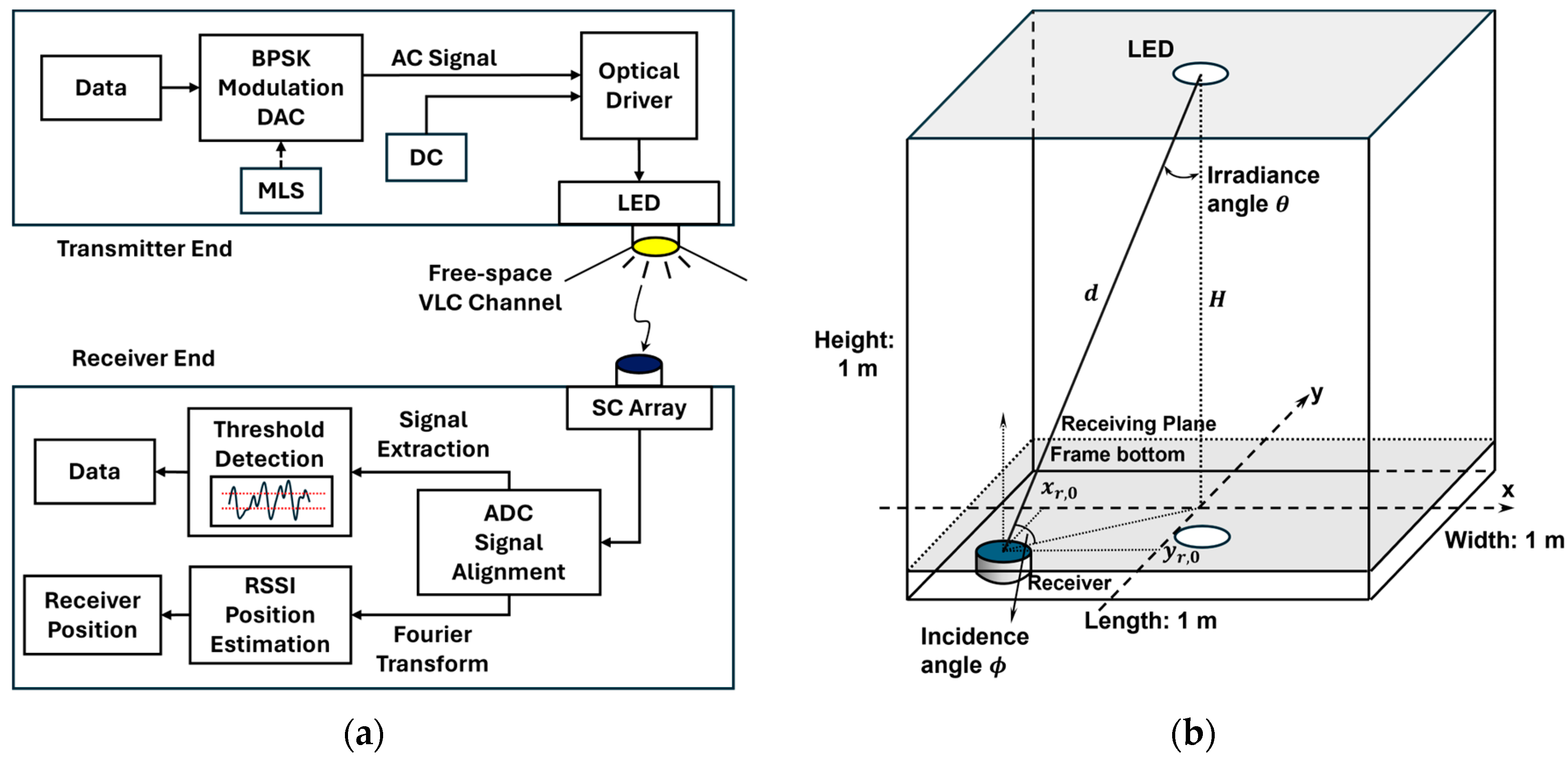
2.1. VLCP System Mechanism

The indoor VLCP system based on one LED and an array of multiple SC receivers proposed in this paper is depicted in Figure 1a and structurally divided into three sections: the transmitter, the free-space VLC channel, and the receiver. For the user data to be transmitted, the maximum length sequence (MLS or m-sequence) is initially attached to its head and tail for signal synchronization and extraction. Then, the combined data, modulated by binary phase shift keying (BPSK), are converted into an alternating current (AC) analog signal by a digital-to-analog converter (DAC). Subsequently, an optical driver supplies both direct current (DC) and AC signals to the LED, achieving the required drive voltage to convert electrical energy into light. The optical signal carrying the VLCP information exits the transmitter and propagates through the free space VLC channel, ultimately arriving at the effective detection surface of the SC array, where it undergoes photovoltaic conversion. The received electrical signal is then reconverted into a digital signal by an analog-to-digital converter (ADC). After utilizing the MLS for signal alignment and extraction, on the one hand, the data are demodulated through threshold judgment for VLC; on the other hand, the RSS is calculated using the Fourier transform method, thereby calculating the signal transmission distances to determine the receiver’s location via the RATT-VLP algorithm for VLP. Thus, the system is capable of simultaneous signal transmission and receiver-positioning functions. We will elaborate on the principles of implementing VLCP in the following sections.
Firstly, we consider the user data b[n]∈{−1, 1}; thus, the n-th symbol is expressed as
s t = b n ,      n T s t < n + 1 T s ,
where T s is the symbol period. The BPSK-modulated signal can be expressed as
S t = s t · cos 2 π f c t ,
where f c denotes the carrier frequency. Now, the transmitted VLCP signal can be written as
T t = P t α S t + 1 ,
where P t is the DC transmit power of LED, and α is defined as the ratio of the maximum current variation of the modulated signal to the LED bias current [21,22].
Then, the VLCP signal propagates through the VLC channel, as depicted in Figure 1b. The intensity of the system’s LED transmitter is assumed to follow the Lambertian emission model, expressed as I θ = I 0 cos m θ , where θ is the angle of emission. Given that existing research indicates that the Non-Line-of-Sight (NLoS) component of VLC channels is significantly smaller than the Line-of-Sight (LoS) component [23] and considering the integrative effect, which mitigates multipath interference [5], this paper disregards the channel’s NLoS components. It is assumed that the LED is parallel to the receiving plane, and its vertical distance from the receiving plane is H . Under these assumptions, the DC gain of the channel in this VLCP model can be determined by the following equation:
G 0 = m + 1 A H m + 1 2 π d m + 3 G F ϕ g c ϕ             0 ϕ Φ c 0                                                                                                     ϕ > Φ c           ,
where m is the Lambertian emission order related to the semi-angle at half-power (or the viewing half angle) of the LED. ϕ is the angle of incidence; A is the effective detection area of the detector; d is the distance between the LED and the detector; G F ϕ is the gain of the optical filter; and g c ϕ is the gain of the optical concentrator, which is related to the refractive index of the detector ,   n ,   and the width of the field of view,   Φ c ,   at the receiver, expressed as
g c ϕ = n 2 sin 2 Φ c               0 ϕ Φ c 0                                         0 Φ c         .
Therefore, the received VLCP signal with the DC component removed can be expressed as
R t = G 0 · P t α S t = m + 1 A H m + 1 2 π d m + 3 G F ϕ g c ϕ · P t α S t + N .
where N denotes the noise during the signal transmission process.
For VLC, through the method of threshold judgment accomplished by comparing the received signal value with the threshold, ξ , the received signal can be demodulated to obtain the user data. The recovered n -th symbol, r n , of user data can be described as
r t = 1 ,         R t ξ 1 ,             R t < ξ .
For VLP, we define the maximum power spectral density (PSD) of a received signal as the RSS, which is calculated by performing a Fourier transform on the signal and then taking the square of the magnitude of the resulting frequency components. Given that the incident angle, ϕ , is less than or equal to the field of view, Φ c , the RSS at the i-th SC receiver, P r , i , can be represented as follows:
P r , i = max F R i t 2 = m + 1 A i H m + 1 2 π d i m + 3 G F , i ϕ g c , i ϕ · P t + N ,
With the fixed parameters associated with specific SC receivers and structures defined as χ i = m + 1 A i G F , i ϕ g c , i ϕ H m + 1 P t / 2 π , the signal transmission distance between the i-th SC receiver and the LED can be derived from the following equation:
d i = χ 1 m + 3 · P r i N 1 m + 3 ,
After obtaining the signal transmission distances between the LED and all SC receivers, we use the RATT-VLP algorithm to locate the receiver. Figure 2 depicts the spatial positioning and distribution of the array of SC receivers in the proposed VLCP system. The array consists of three solar cells, SC1, SC2, and SC3, arranged in an L-shaped configuration with SC1 at the vertex and separated from SC2 and SC3 by distance,   d p . With SC1’s coordinates at ( x 0 , y 0 ) , SC2 is located at ( x 0 + d p , y 0 ) , and SC3 at ( x 0 , y 0 + d p ) . The distances from the LED to SC1, SC2, and SC3 can be calculated as follows:
d 1 2 = x 0 2 + y 0 2 + H 2 d 2 2 = x 0 + d p 2 + y 0 2 + H 2 = x 0 2 + y 0 2 + H 2 + d p 2 + 2 x 0 d p d 3 2 = x 0 2 + y 0 + d p 2 + H 2 = x 0 2 + y 0 2 + H 2 + d p 2 + 2 y 0 d p ,
The coordinate of SC1 can be derived as
x 0 = d 2 2 d 1 2 d p 2 2 d p y 0 = d 3 2 d 1 2 d p 2 2 d p ,
Thus, the location of the receiver that we define as the coordinate of SC1 can be determined.

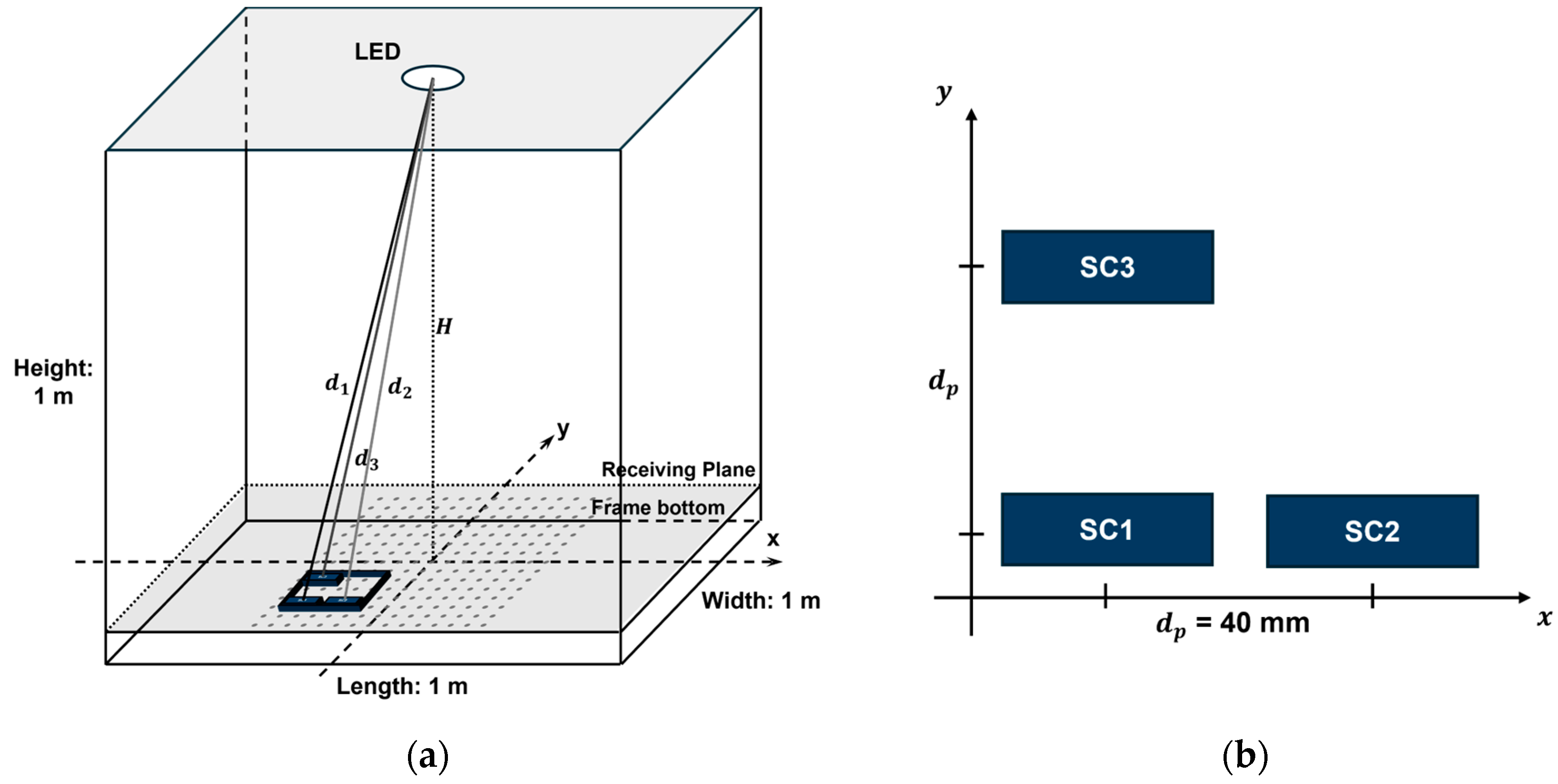
2.2. Experimental Setup

The experimental setup is shown in Figure 3a, featuring a frame measuring 1 m × 1 m × 1 m. Centrally mounted on the top of the frame is a commercial LED with an output power of 3W, while a homemade SC receiver is positioned on the bottom receiving plane. The vertical separation between the LED and the receiving plane is 92 cm. The L-shaped SC array is composed of three commercially available ANYSOLAR KXOB25-14X1F rectangular monocrystalline silicon solar cells, each boasting a typical power conversion efficiency (PCE) of 25%. These solar cells each have an effective reception area of 21.5 mm × 6.59 mm and are spaced 40 mm apart from each other.
Figure 3b is the schematic block diagram of the process for transmitting and receiving signals. Initially, a random BPSK data sequence is generated, and m-sequences are appended to its head and tail to facilitate data alignment at the receiver. The m-sequence exhibits excellent autocorrelation properties, which aids in extracting the data sequences through autocorrelation calculations in signal processing. Subsequently, the transmission signal is modulated using a RIGOL DG2102 arbitrary waveform generator (AWG), and a DC power supply is provided to the LED by setting a bias voltage. The peak-to-peak voltage ( V p p ) of the signal is set at 2 V, the bias voltage ( V d c ) is 6 V, and the sampling rate is 50 kSa/s. Next, the SC array receiver is employed to capture the transmitted signal using a RIGOL MSO5354 oscilloscope (OSC) with a sampling rate of 5 MSa/s. A photograph of the homemade SC array receiver is also presented in the lower right corner of Figure 3a. To enhance the electrical signals output by the three SCs, a low-noise JFET quad operational amplifier, STMicroelectronics TL074CDT, is employed within the SC array receiver. The amplified signals are subsequently transmitted to an oscilloscope through a 50-ohm RF adapter for signal acquisition. The captured signals are then transferred to a computer for further processing.
To evaluate the system’s communication performance, the bias voltage of the LED is adjusted, and the sampling rate of the AWG is tuned under stable conditions to achieve the highest possible rate. At the receiving end, the received signals are autocorrelated with the original m-sequence according to its autocorrelation property. Signal alignment is then performed based on the position of the peak in the autocorrelation coefficient, followed by the demodulation of the signals using the threshold judgment method.
To assess the positioning ability of the system, the SC array receiver moves parallel across the receiving plane, forming a uniformly distributed grid of 15 × 15 test points centered around the origin of the receiving surface. Each adjacent test point is spaced 5 cm apart, yielding a total of 225 positioning data points. Finally, the received signals are processed using a computer to extract the corresponding signal segments. By utilizing the autocorrelation property of the m-sequence, the initially attached m-sequence is auto-correlated with the received signal sequence. The peak value of the computed autocorrelation coefficient indicates the starting point of the m-sequence within the received signal sequence, allowing for synchronization and data extraction. Then, the PSDs are calculated using Fourier transform methods, as with the RSS. Here, due to the complexity of the experimental environment, the experimental results may deviate from theoretical calculations. To minimize experimental errors, we used an exponential nonlinear curve-fitting method to model the relationship between RSS and signal transmission distance, as shown in Equation (9). The results of these experiments will be discussed in the following section.

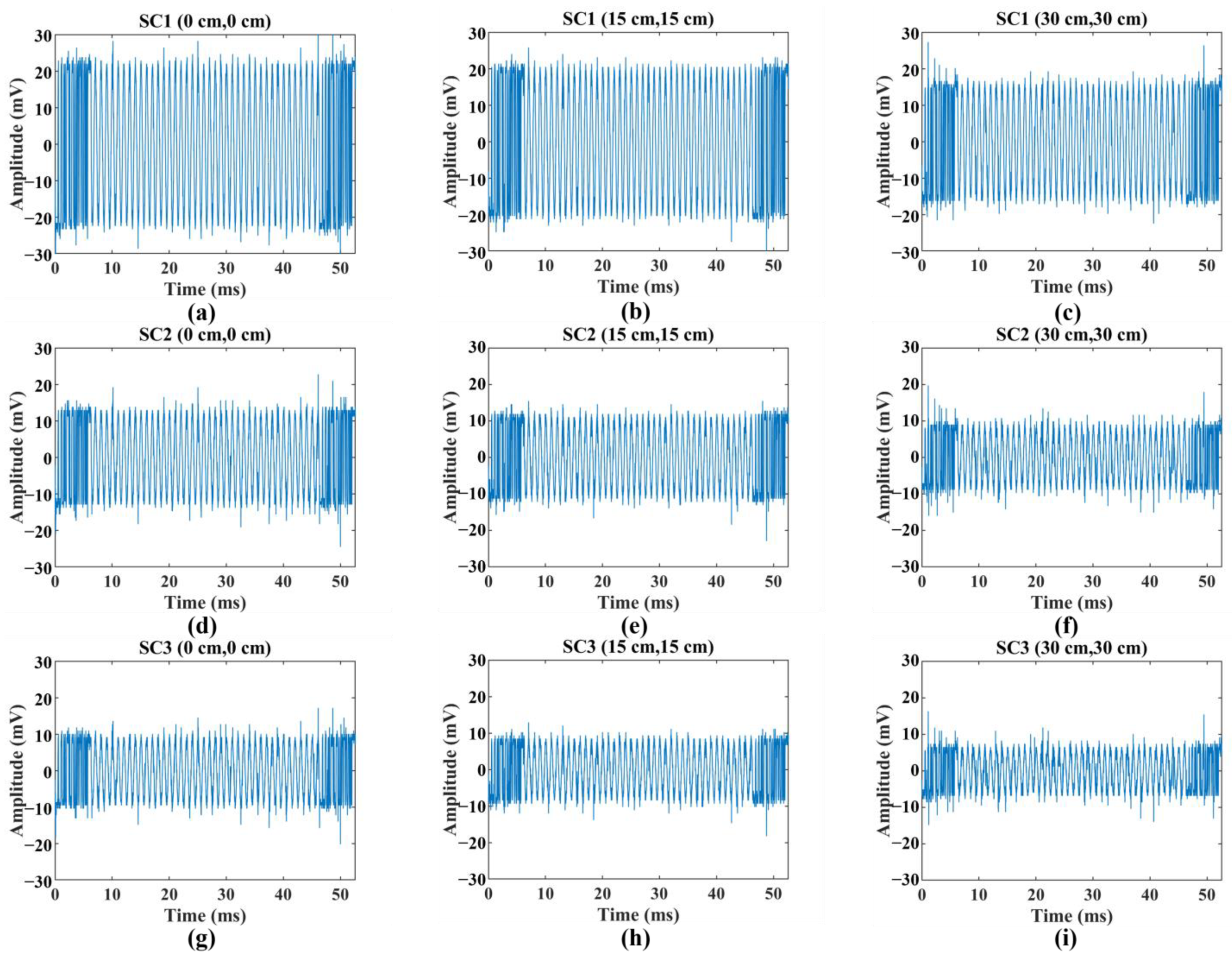
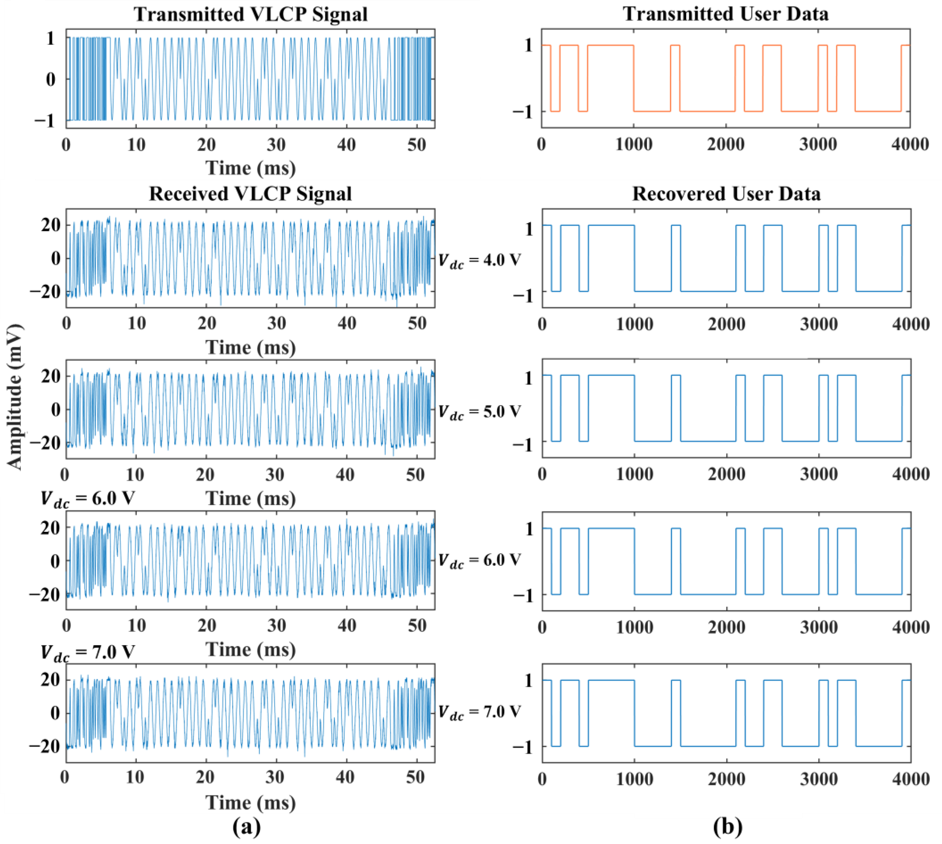
3. Results and Discussion

Figure 4 shows the downsampled sinusoidal waveforms received by SC1, SC2, and SC3 at three selected points on the diagonal of the receiving plane: point A (0 cm, 0 cm), point B (15 cm, 15 cm), and point C (25 cm, 25 cm). The received sine signals are downsampled according to the ratio of the sampling rates of the oscilloscope (OSC) and the arbitrary waveform generator (AWG), and their AC components are extracted. The waveforms at each point, as illustrated in the figure, contain noise and exhibit amplitude variations across different points. These will be processed later to ascertain specific signal strengths. Furthermore, Figure 5 showcases the waveforms of the BPSK signals received at point A under varying LED DC drive voltages, alongside the results of their demodulation and a comparison with the original data. All waveforms were successfully demodulated without errors, achieving a maximum data rate of 1.21 kbps. This data rate demonstrates that this SC-based VLCP system possesses adequate capabilities for supporting common low-speed VLC schemes, which may include applications where high-data-rate transmission is not critical, such as in sensor networks, smart lighting systems, or basic indoor positioning systems with lower polling rates.
By performing a Fourier transform on the extracted signals collected from various points on the receiving surface, the corresponding signal strength was calculated. This method facilitated the estimation of the RSS distributions across the receiving plane for the three SCs, as illustrated in Figure 6. The RSS distributions for all three SCs exhibited a clear pattern, with lower values around the periphery than at the center. Additionally, the maximum RSS values for SC2 and SC3 were observed to shift toward the negative x-axis and negative y-axis, respectively. These shifts can be attributed to the L-shaped arrangement of the SCs, with SC2 positioned along the positive x-axis and SC3 along the positive y-axis. The experimental results were consistent with expectations and correctly reflected the spatial orientation of the SCs within the receiver.
After estimating the RSS for each SC channel, we applied a fitting method to derive a set of fitting functions based on Equation (9). The regression curves, representing the transmission distances between the LED and each corresponding SC, exhibited clear exponential decay. The derived fitting functions for estimating the transmission distance,   d i , from the i -th SC’s RSS, P r , i , are as follows:
d ~ 1 = 84.65 + 39.43 exp 3.458 · P r , 1 d ~ 2 = 79.59 + 35.49 exp 12.63 · P r , 2 d ~ 3 = 85.35 + 34.58 exp 10.30 · P r , 3 ,
To accurately quantify the precision of the transmission distance estimates within our system, we utilized the transmission distance error (TDE) metric, which measures the absolute difference between the estimated and theoretical transmission distances. The distributions of TDE are shown in Figure 7, illustrating a clear trend: the TDE increases as the distance from the center increases. This observed pattern indicates that the accuracy of the VLP system diminishes as the distance increases, likely due to factors such as signal attenuation and environmental interference.
By using Equation (11), we calculated the estimated positions of the test points, and the positioning results are displayed in Figure 8a. To enhance clarity in the diagram, only the central 11 × 11 points are retained, as more significant deviations were observed at the periphery points. In the figure, blue dots represent the theoretical positions of the test points, while red stars indicate the estimated positions. Lines connecting these points help visually illustrate the degree of positioning deviation.
From the figure, it is evident that within the central 7 × 7 points, covering a 30 cm × 30 cm area, the deviation between the estimated positions and the theoretical positions is relatively small. We conducted a statistical analysis of the positioning errors for the central 7 × 7 points, the central 11 × 11 points, and all 15 × 15 points, with the results shown in Figure 8b. For the 7 × 7 points, the positioning errors are well concentrated within 5 cm, with an average error of 3.40 cm. For the larger area of 11 × 11 points, most positioning errors are less than 10 cm. However, for all test points, the average error is 10.49 cm. The box plot shows that the median lines of the three groups of statistical data are all lower than the mean values. Additionally, as more peripheral points are included, this skewness gradually increases. This indicates that the positioning errors of the peripheral points significantly raise the overall positioning error, while the errors of the central points remain low. Figure 8c shows the cumulative number of points that are less than the corresponding positioning error; out of the total 225 test points in the experiment, 82 points had positioning errors of less than 5 cm, and over 140 points had errors of less than 10 cm. As the positioning error increases, the increment in the number of points gradually decreases, supporting the above observations. Overall, the VLCP system demonstrated good positioning accuracy.
As the positioning area increases, the discrepancy between the theoretical and estimated positions begins to increase significantly. Given the comprehensive consideration of previous results, this could be attributed to several factors. Firstly, the SCs used may have a poor low-light response, making it challenging to distinguish RSS accurately at the periphery, where the light intensity is relatively lower than the central area. Secondly, the undefined far-field light intensity distribution of the LED used in the experiments might contribute to the errors, especially if the LED has a narrow viewing half-angle, leading to a rapid decline in RSS measurements beyond the 50 cm × 50 cm area. Additionally, noise introduced by the receiver’s peripheral circuitry could also be a contributing factor to these errors.
Lastly, we compared the results of this work with previous PD/SC-based VLC/VLP methods, as shown in Table 1. As the first single-source SC-VLCP, our work is unique in simultaneously achieving visible light communication and positioning using a solar cell. The VLC system in [12] is based on an α-Si SC panel, achieving a rate of 11.84 Mbps by applying OFDM, but it does not have VLP capability. This work can provide a reference for us to apply more advanced modulation techniques in the future. Refs. [10,24] present common multi-source VLP systems based on PD and APD, respectively. Compared with these, our work still lags slightly behind in overall positioning accuracy compared with PD-based methods, though it achieves comparable accuracy in narrow-range positioning. This also provides data for future optimization efforts.

4. Future Work

Throughout this study, the feasibility of using SC as a VLCP receiver has been validated, achieving an initiative simultaneous SC-VLCP system with vast potential for applications in light-source-limited scenarios. Based on our work, it is believed that various derivative directions merit further investigation, including but not limited to channel model investigation; hardware optimization of SC receivers; and the integration of visible light communication, positioning, and energy harvesting within the SLIPT framework.
For channel model investigation, future research could include the further simulation of channel models that include NLoS components, particularly in SC-based VLCP systems. Advanced simulation techniques could be employed to model channel behavior under various reflection conditions, and practical experiments could be conducted that include complex indoor environmental factors [25]. This will help evaluate and quantify the overall impact of NLoS propagation on system communication performance and positioning accuracy. These steps are crucial for optimizing system design, enhancing the robustness of positioning algorithms, and advancing the application of SC-VLCP technology in real-world complex environments.
For hardware optimization, a well-designed receiver circuit could help obtain high-quality VLCP signals. Future work could involve optimizing the circuit design of the SC array receiving module to reduce the impact of circuit noise on the received signal, including implementing stricter power supply noise shielding and applying advanced filtering circuits. Applying nonlinear compensation circuits for SC under low illumination may also help improve the overall performance of the system [26].
For energy harvesting, the efficiency of solar cells and optimization strategies within the SLIPT framework could be key focus areas for future research. The next steps of this work could involve discussing and verifying methods to improve the energy harvesting efficiency of SC receivers and achieve self-powered receivers, enabling the simultaneous implementation of visible light communication, positioning, and energy harvesting. Emerging solar cells with novel structures and materials could be applied to achieve significant improvements in rate and power conversion efficiency [27]. Signal modulation and demodulation techniques could also be optimized, and efficient resource allocation strategies are worth studying to enhance the applicability of SC-VLCP systems. These advancements will help fully optimize and extend the application of SLIPT in VLCP systems.

5. Conclusions

This paper proposed a solar-cell-array-based indoor VLCP system with a single LED transmitter, coupled with the RATT-VLP algorithm based on multiple SC receivers. The LED emits VLCP signals that pass through the VLC channel and are captured by the SC array, serving dual purposes for communication and positioning. The alignment of the received BPSK signals is achieved through autocorrelation with an MLS, and the data are demodulated using threshold judgment. The RSS calculations employ the Fourier transform method, and the receiver position is determined using RATT-VLP. Experimental validation confirmed the feasibility of the proposed VLCP system and the RATT-VLP algorithm. For BPSK-modulated signals, the highest measured VLC communication data rate for this VLCP system was 1.21 kbps, demonstrating its ability to support low-speed VLC applications. Furthermore, the RATT-VLP algorithm applied within this VLCP system achieved an average positioning accuracy of 3.40 cm within a 30 cm × 30 cm area, with an overall average accuracy of 10.49 cm. The results showcase the SC array-based indoor VLCP system’s potential for implementing communication and positioning functions simultaneously. Finally, future research directions based on this work are provided, including but not limited to channel model investigation, SC receiver hardware and circuitry optimization, and energy harvesting efficiency improvement for achieving SC-VLCP systems under the SLIPT concept.

Author Contributions

Conceptualization, D.X. and Z.L.; methodology, D.X. and Z.L.; software, D.X.; validation, D.X.; formal analysis, D.X.; investigation, D.X.; resources, C.Y.; data curation, D.X.; writing—original draft preparation, D.X.; writing—review and editing, D.X. and Z.L.; visualization, D.X.; supervision, C.Y.; project administration, C.Y.; funding acquisition, C.Y. All authors have read and agreed to the published version of the manuscript.

Funding

This research was funded by the Hong Kong Research Grants Council, grant number GRF15212720.

Institutional Review Board Statement

Not applicable.

Informed Consent Statement

Not applicable.

Data Availability Statement

The data underlying the results presented in this paper are not publicly available at this time but may be obtained from the authors upon reasonable request.

Conflicts of Interest

The authors declare no conflicts of interest.

References

  1. Pathak, P.H.; Feng, X.; Hu, P.; Mohapatra, P. Visible light communication, networking, and sensing: A survey, potential and challenges. IEEE Commun. Surv. Tutor. 2015, 17, 2047–2077. [Google Scholar] [CrossRef]
  2. Karunatilaka, D.; Zafar, F.; Kalavally, V.; Parthiban, R. LED based indoor visible light communications: State of the art. IEEE Commun. Surv. Tutor. 2015, 17, 1649–1678. [Google Scholar] [CrossRef]
  3. Lee, S.H.; Jung, S.Y.; Kwon, J.K. Modulation and coding for dimmable visible light communication. IEEE Commun. Mag. 2015, 53, 136–143. [Google Scholar] [CrossRef]
  4. Lou, P.; Zhang, H.; Zhang, X.; Yao, M.; Xu, Z. Fundamental analysis for indoor visible light positioning system. In Proceedings of the 2012 1st IEEE International Conference on Communications in China Workshops (ICCC), Beijing, China, 15–17 August 2012; pp. 59–63. [Google Scholar] [CrossRef]
  5. Komine, T.; Nakagawa, M. Integrated system of white LED visible-light communication and power-line communication. IEEE Trans. Consum. Electron. 2003, 49, 71–79. [Google Scholar] [CrossRef]
  6. Liu, Z.; Yu, C. Multi-user visible light communication and positioning system based on dual-domain multiplexing scheme. Photonics 2023, 10, 306. [Google Scholar] [CrossRef]
  7. Yu, C.; You, X.; Liu, Z.; Chen, J. Conceptual design for indoor visible light communication and positioning cooperative systems. In Proceedings of the 22nd International Conference on Transparent Optical Networks (ICTON) 2020, Bari, Italy, 19–23 July 2020. [Google Scholar] [CrossRef]
  8. Zhang, Y.; Wei, Z.; Liu, Z.; Cheng, C.; Wang, Z.; Tang, X.; Yang, Y.; Fu, H.Y. Optical communication and positioning convergence for flexible underwater wireless sensor network. J. Light. Technol. 2023, 41, 5321–5327. [Google Scholar] [CrossRef]
  9. Shao, S.; Salustri, A.; Khreishah, A.; Xu, C.; Ma, S. R-VLCP: Channel Modeling and Simulation in Retroreflective Visible Light Communication and Positioning Systems. IEEE Internet Things J. 2023, 10, 11429–11439. [Google Scholar] [CrossRef]
  10. Yang, H.; Chen, C.; Zhong, W.D.; Alphones, A.; Zhang, S.; Du, P. Demonstration of a Quasi-Gapless Integrated Visible Light Communication and Positioning System. IEEE Photonics Technol. Lett. 2018, 30, 2001–2004. [Google Scholar] [CrossRef]
  11. Kim, S.M.; Won, J.S.; Nahm, S.H. Simultaneous reception of solar power and visible light communication using a solar cell. Opt. Eng. 2014, 53, 046103. [Google Scholar] [CrossRef]
  12. Wang, Z.; Tsonev, D.; Videv, S.; Haas, H. On the design of a solar-panel receiver for optical wireless communications with simultaneous energy harvesting. IEEE J. Sel. Areas Commun. 2015, 33, 1612–1623. [Google Scholar] [CrossRef]
  13. Shin, W.H.; Yang, S.H.; Kwon, D.H.; Han, S.K. Self-reverse-biased solar panel optical receiver for simultaneous visible light communication and energy harvesting. Opt. Express 2016, 24, A1300–A1305. [Google Scholar] [CrossRef] [PubMed]
  14. Diamantoulakis, P.D.; Karagiannidis, G.K.; Ding, Z. Simultaneous lightwave information and power transfer (SLIPT). IEEE Trans. Green Commun. Netw. 2018, 2, 764–773. [Google Scholar] [CrossRef]
  15. Wang, Z.; Tsonev, D.; Videv, S.; Haas, H. Towards self-powered solar panel receiver for optical wireless communication. In Proceedings of the 2014 IEEE International Conference on Communications (ICC), Sydney, NSW, Australia, 10–14 June 2014; pp. 3348–3353. [Google Scholar] [CrossRef]
  16. Lorrière, N.; Bialic, E.; Pasquinelli, M.; Chabriel, G.; Barrere, J.; Escoubas, L.; Simon, J.J. An OFDM testbed for LiFi performance characterization of photovoltaic modules. In Proceedings of the 2018 Global LIFI Congress (GLC), Paris, France, 8–9 February 2018; pp. 1–5. [Google Scholar] [CrossRef]
  17. Sepehrvand, S.; Theagarajan, L.N.; Hranilovic, S. Rate-power trade-off in simultaneous lightwave information and power transfer systems. IEEE Commun. Lett. 2020, 25, 1249–1253. [Google Scholar] [CrossRef]
  18. Fakidis, J.; Helmers, H.; Haas, H. Simultaneous wireless data and power transfer for a 1-Gb/s GaAs VCSEL and photovoltaic link. IEEE Photonics Technol. Lett. 2020, 32, 1277–1280. [Google Scholar] [CrossRef]
  19. Das, S.; Sparks, A.; Poves, E.; Videv, S.; Fakidis, J.; Haas, H. Effect of sunlight on photovoltaics as optical wireless communication receivers. J. Light. Technol. 2021, 39, 6182–6190. [Google Scholar] [CrossRef]
  20. Hsu, C.W.; Wu, J.T.; Wang, H.Y.; Chow, C.W.; Lee, C.H.; Chu, M.T.; Yeh, C.H. Visible light positioning and lighting based on identity positioning and RF carrier allocation technique using a solar cell receiver. IEEE Photonics J. 2016, 8, 7905507. [Google Scholar] [CrossRef]
  21. Wang, Z.; Zhong, W.-D.; Yu, C.; Chen, J.; Francois, C.P.S.; Chen, W. Performance of dimming control scheme in visible light communication system. Opt. Express 2012, 20, 18861–18868. [Google Scholar] [CrossRef] [PubMed]
  22. Neokosmidis, I.; Kamalakis, T.; Walewski, J.W.; Inan, B.; Sphicopoulos, T. Impact of Nonlinear LED Transfer Function on Discrete Multitone Modulation: Analytical Approach. J. Light. Technol. 2009, 27, 4970–4978. [Google Scholar] [CrossRef]
  23. Komine, T.; Nakagawa, M. Fundamental analysis for visible-light communication system using LED lights. IEEE Trans. Consum. Electron. 2004, 50, 100–107. [Google Scholar] [CrossRef]
  24. Raes, W.; Knudde, N.; De Bruycker, J.; Dhaene, T.; Stevens, N. Experimental Evaluation of Machine Learning Methods for Robust Received Signal Strength-Based Visible Light Positioning. Sensors 2020, 20, 6109. [Google Scholar] [CrossRef]
  25. Dos Santos, D.R.; Julien-Vergonjanne, A.; Dkhil, S.B.; Parmentier, M.; Combeau, P.; Sahuguède, S.; Bouclé, J. Toward Indoor Simulations of OPV Cells for Visible Light Communication and Energy Harvesting. IEEE Access 2024, 12, 41027–41041. [Google Scholar] [CrossRef]
  26. Chen, S.; Liu, L.; Chen, L.K. Passive Nonlinear Compensation Circuits for Photovoltaic Visible Light Communications under Low Illuminance. In Proceedings of the Optical Fiber Communication Conference (OFC) 2022, San Diego, CA, USA, 6–10 March 2022; p. W2A.32. [Google Scholar]
  27. Fu, Y.; Zhang, L.; Wangzhou, Y.; Zheng, S.; Sun, Y.; Liu, J.; Zhang, Y.; Li, S.; Hu, Z.; Yu, B.; et al. Wavelength division multiplexing visible light communication with wide incident angle enabled by perovskite quantum dots. Opt. Commun. 2024, 559, 130427. [Google Scholar] [CrossRef]
Figure 1. (a) Schematic diagram of indoor SC-array-based VLCP system and (b) diagram of the indoor VLCP system model.
Photonics 11 00536 g001
Figure 2. (a) Spatial positioning of the SC array receiver within the SC-array-based VLCP system; (b) configuration of the SC array.
Photonics 11 00536 g002
Figure 3. (a) Diagram of the experimental platform for the SC-array-based VLCP system and (b) schematic block diagram of the SC array receiver.
Photonics 11 00536 g003
Figure 4. Downsampled waveforms received by SC1 (a) at point A, (b) at point B, and (c) at point C; downsampled waveforms received by SC2 (d) at point A, (e) at point B, and (f) at point C; downsampled waveforms received by SC3 (g) at point A, (h) at point B, and (i) at point C.
Photonics 11 00536 g004
Figure 5. VLCP signal (a) waveforms and (b) demodulation results received by SC1 at point A under different LED DC drive voltages.
Photonics 11 00536 g005
Figure 6. The RSS distributions of (a) SC1, (b) SC2, and (c) SC3.
Photonics 11 00536 g006
Figure 7. The transmission distance error of (a) SC1, (b) SC2, and (c) SC3.
Photonics 11 00536 g007
Figure 8. (a) The positioning results, including estimated position and real position; (b) box plots of positioning error within central 7 × 7 points, 11 × 11 points, and 11 × 11 points; (c) cumulative number of points below respective positioning errors.
Photonics 11 00536 g008
Table 1. Comparison of this work with previous PD/SC-based VLC/VLP methods.
RefIlluminationReceiver TypeRatePositioning ErrorNote
This workSingle white LEDMonocrystalline Si
SC Array
1.21 kbpsNarrow-range 3.40 cm;
wide-range 10.49 cm
First single-source SC-VLCP
[12]Single white LEDα-Si SC Panel11.84 Mbps (OFDM)N/AVLC
[24]4 White LEDsSi PDN/A4 cmVLP
[10]3 White LEDsAPDN/A6.08 cmVLP
Disclaimer/Publisher’s Note: The statements, opinions and data contained in all publications are solely those of the individual author(s) and contributor(s) and not of MDPI and/or the editor(s). MDPI and/or the editor(s) disclaim responsibility for any injury to people or property resulting from any ideas, methods, instructions or products referred to in the content.

