Communication

Design of Channel Drop Filters Based on Photonic Crystal with a Dielectric Column with Large Radius inside Ring Resonator

School of Integrated Circuit Science and Engineering, Tianjin University of Technology, Tianjin 300384, China
*
Author to whom correspondence should be addressed.
Photonics 2024, 11(6), 554; https://doi.org/10.3390/photonics11060554
Submission received: 13 May 2024 / Revised: 9 June 2024 / Accepted: 10 June 2024 / Published: 12 June 2024
(This article belongs to the Section Optoelectronics and Optical Materials)

Abstract

:
Photonic crystal channel drop filters (CDFs) play a vital role in optical communication owing to their ability to drop the desired channel. However, it remains challenging to achieve high-efficiency CDFs. Here, we demonstrate a highly efficient three-channel CDF with both high transmission and high quality (Q) factor based on a novel ring resonator that is in the middle of two waveguides. A dielectric column with a large radius replaces the homogeneously distributed dielectric columns inside the ring cavity to modulate the coupling ratio with a straight waveguide, thereby enhancing the transmission and Q factor. The transmission and Q factor of the single-cavity filter are 99.7% and 12,798.4, respectively. The mean value of the three-channel filter based on the basic unit can reach up to 94.6% and 10,617, respectively, and a crosstalk between −30.16 and −50.61 dB is obtained. The proposed CDFs provide efficient filter capability, which reveals great potential in integrated optoelectronics and optical communication.

1. Introduction

Photonic crystals (PhCs) [1] are artificial materials composed of homogeneous and periodic dielectric nanostructures that exhibit the capacity to operate the spread of light owing to their unique properties of photonic localization [2] and photonic band gap (PBG) [3]. Hence, PhCs are propitious for the design and fabrication of optical devices, for instance, optical switches [4], optical sensors [5], optical logic gates [6], optical analog-to-digital converters [7], optical polarizers [8,9,10] and optical CDFs [11,12]. There are methods for preparing photonic crystal devices, such as photolithography [13] and ion beam etching [14].
Optical filters are widely used in optical communications, optical sensors, laser systems, spectral imaging systems [15] and other fields due to their ability to filter certain wavelengths. Currently, there are numerous techniques available for fabricating optical filters, including ring resonators [16], waveguide Bragg gratings [17,18], array waveguide gratings [19,20], Mach–Zehnder Interferometers [21] and PhCs. However, the devices fabricated with photonic crystals typically exhibit nanoscale dimensions, resulting in small size and high integration density. Moreover, PhCs’ periodic arrangement facilitates transformation, and their capability to accommodate fill media simplifies their structural design, rendering them both straightforward and versatile. Currently, there are numerous techniques available for fabricating optical filters. Due to the special characteristics of PhCs mentioned above, a considerable number of recent works have been dedicated to improving the performance of CDFs, which has proven to be a research hotspot. PhC CDFs with a ring resonator in [22] obtained nearly 100 transmissions, but its 1 nm bandwidth resulted in a low quality (Q) factor of 1613, which requires improvement. Eight-channel CDFs with eight PhC ring resonators result in a high Q factor of 5150 and a low average transmissivity of 70.4%, causing high energy consumption [23]. Recently, a ring resonator optical cavity with a square lattice was proposed with a transmittance of 97.4% and a Q factor of 4268, but the characteristics of the multi-channel remain to be investigated for improving utilization efficiency [24]. CDFs with three channel sections and line-defect waveguides has been proposed, and an average drop efficiency of 88% and a Q factor of 4783 have been achieved [25], which has enormous potential to make further progress. Hence, based on the existing research, there is room for improvement in PhC channel drop filters in terms of narrower bandwidth and higher drop efficiency.
In this study, a novel and compact CDF based on a ring resonator and a three-channel CDF obtained by stringing the fundamental element with high transmission and a high Q factor is proposed. By arranging a dielectric rod with a large radius to replace the uniformly arranged dielectric columns inside the ring cavity, the coupling ratio, which is the ratio of the intensity of the optical signal between the resonant cavity and the straight waveguide, is modulated, thereby enhancing the transmissivity and Q factor. Thus, the proposed optical CDFs have significant applications in photonics and optical communication.

2. Description of the CDF Configuration

The proposed two-dimensional CDF is based on the coupling effect [26] between straight PhC waveguides and a ring resonator to achieve the frequency selection of light. To design the PhC CDF, the first step involves extracting the material’s band structure and obtaining the PBG. The fundamental photonic crystal structure is composed of GaSb dielectric rods located in an air medium with a triangular lattice constant of a = 635 nm. The refractive index and radius of the dielectric rods are n = 3.9 [27] and r = 106 nm, respectively. Using the Plane Wave Expansion (PWE) method [28], the corresponding band structure of the photonic crystals with the above-mentioned parameters is shown in Figure 1.
Figure 1 shows that both the TM mode (red areas) and the TE mode (blue areas) have photonic band gaps (PBGs). The PBGs of the TM mode are located in the range of 0.852 ≤ a/λ ≤ 0.911, with corresponding wavelengths of 697.1 nm ≤ λ ≤ 745.3 nm. The PBGs of the TE mode are located in the range of 0.271 ≤ a/λ ≤ 0.473, with corresponding wavelengths of 1342.5 nm ≤ λ ≤ 2343.2 nm. Due to the broad band gap of the TE mode, the following simulations will be conducted in the TE mode.
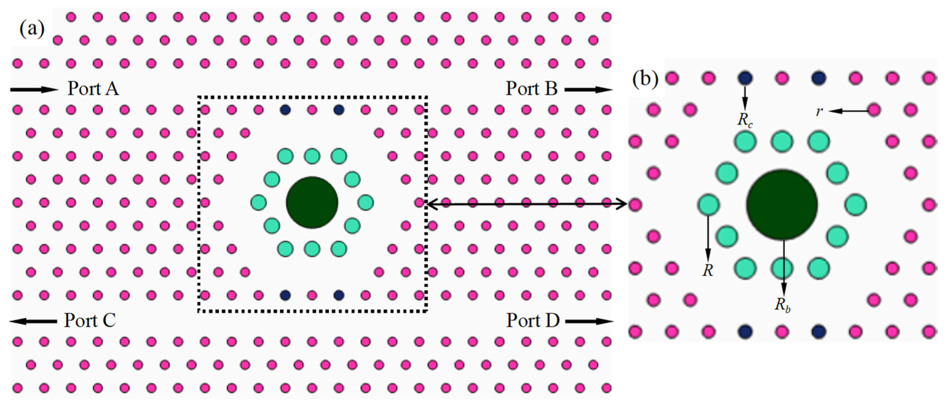
COMSOL Multiphysics is used to analyze the transmission characteristics of the proposed photonic crystal filters. The structure of the proposed CDF is represented in Figure 2. It consists of GaSb dielectric rods with four different radii. The radius of the scattering rods shown in black is Rc = 115 nm, the radius of the green rods is R = 180 nm, and the radius of the dark-green large rods is Rb = 607 nm. The two-line defects in the structure are treated as bus waveguide and dropping waveguide, and the ring-type defect is treated as the resonant cavity. During operation, TE-polarized Gaussian beams are incident from port A, which are coupled into the ring cavity and then coupled out to the other three ports. The ring resonant cavity is designed by arranging a dielectric rod with a large radius to replace the uniformly arranged dielectric rods to achieve high transmission and a high Q factor. The structural parameters of the CDF in the simulation are shown in Table 1.
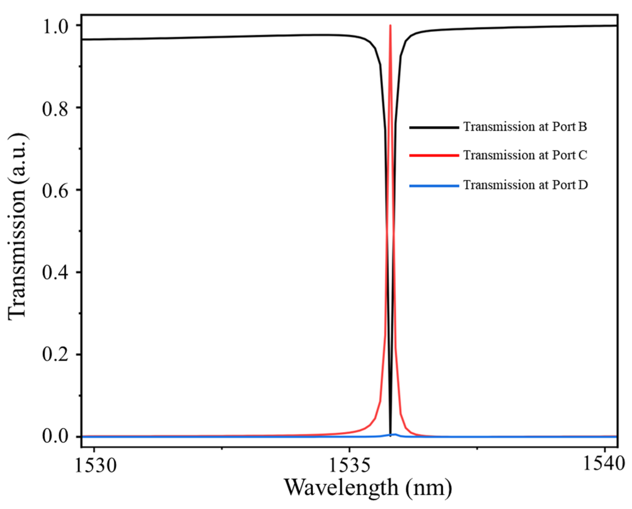
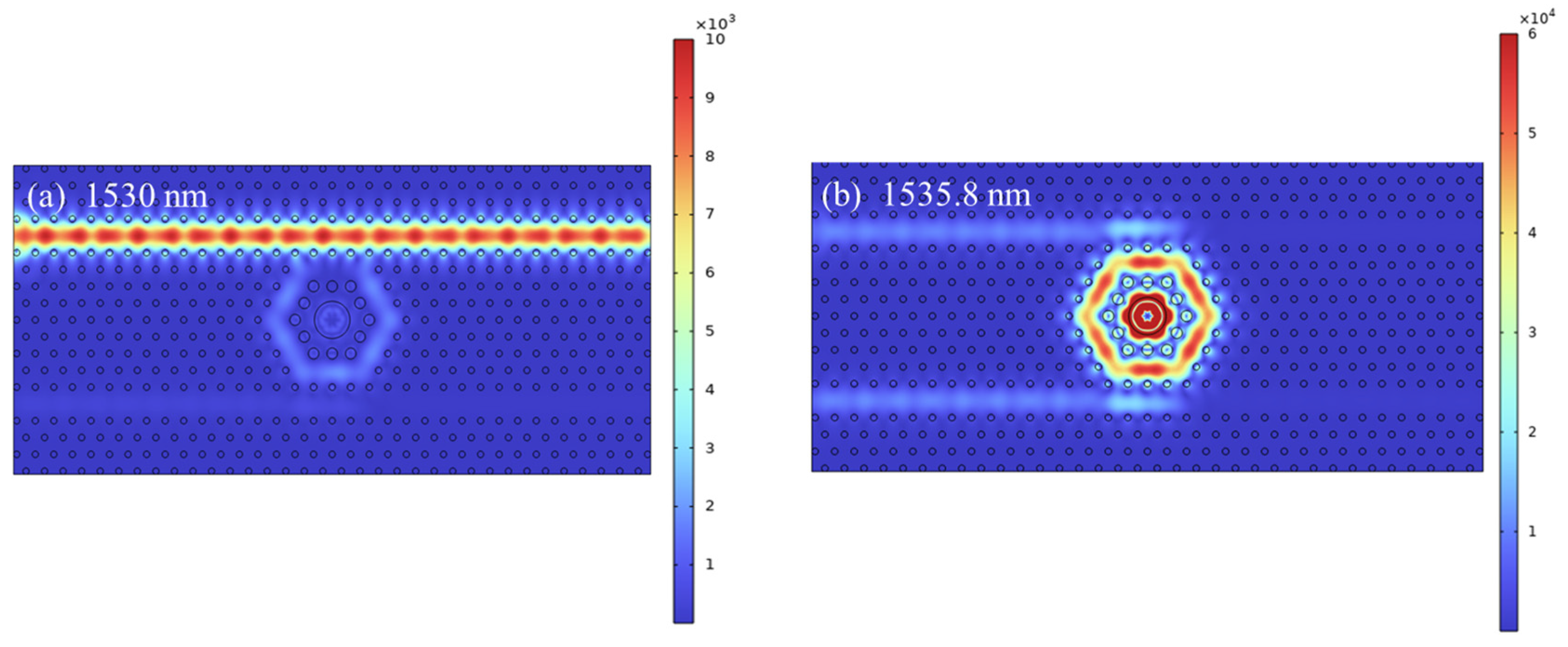
The transmission spectra of the CDF at ports B, C and D are shown in Figure 3. At a wavelength of 1535.8 nm, the transmittance at port C approaches 99.7% (T = Pout/Pin, Pout is the output power of the output port and Pin is the input power of the input port), with a full width half maximum (FWHM) of 0.12 nm and a Q factor of 12,798.4 (Q = f0fλ0λ, f0 and λ0 are the resonant frequency and resonant wavelength, respectively, and Δλ is the FWHM). This is because the resonant frequency of the cavity corresponds to a frequency of 1535.8 nm, thus the incident light is almost completely coupled into the cavity and coupled out to port C. However, light with a wavelength different from the resonant wavelength is unable to couple into the ring cavity, thus resulting in a drop in the spectrum at port B. The transmittance at port D approaches zero even at the resonant wavelength, which is the idle port. The distribution of the electric fields of |Ez| at 1530 nm and 1535.8 nm is displayed in Figure 4a,b, which show that there is a strong resonance at 1535.8 nm for the CDF and minimal light coupling at 1530 nm.
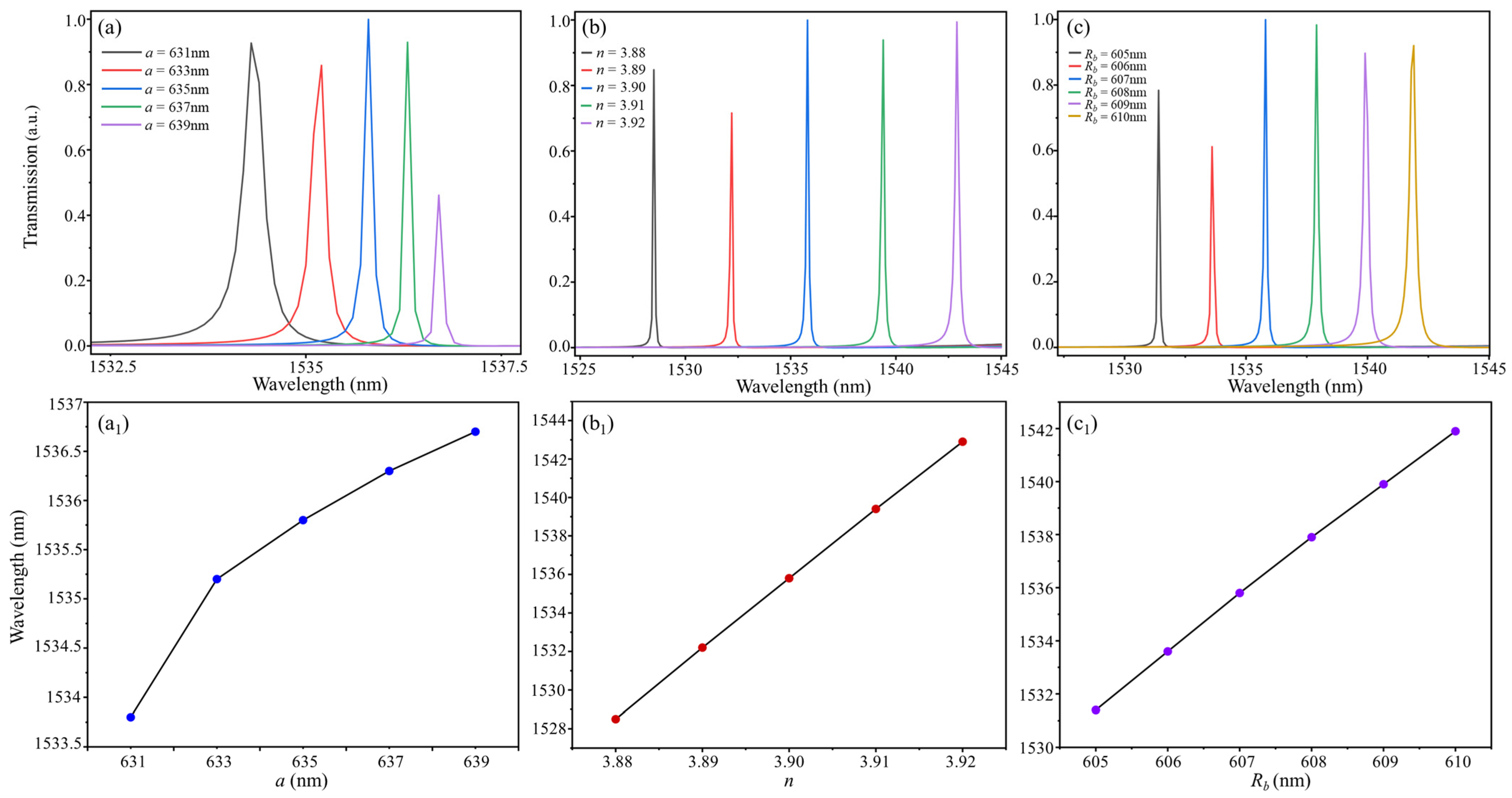
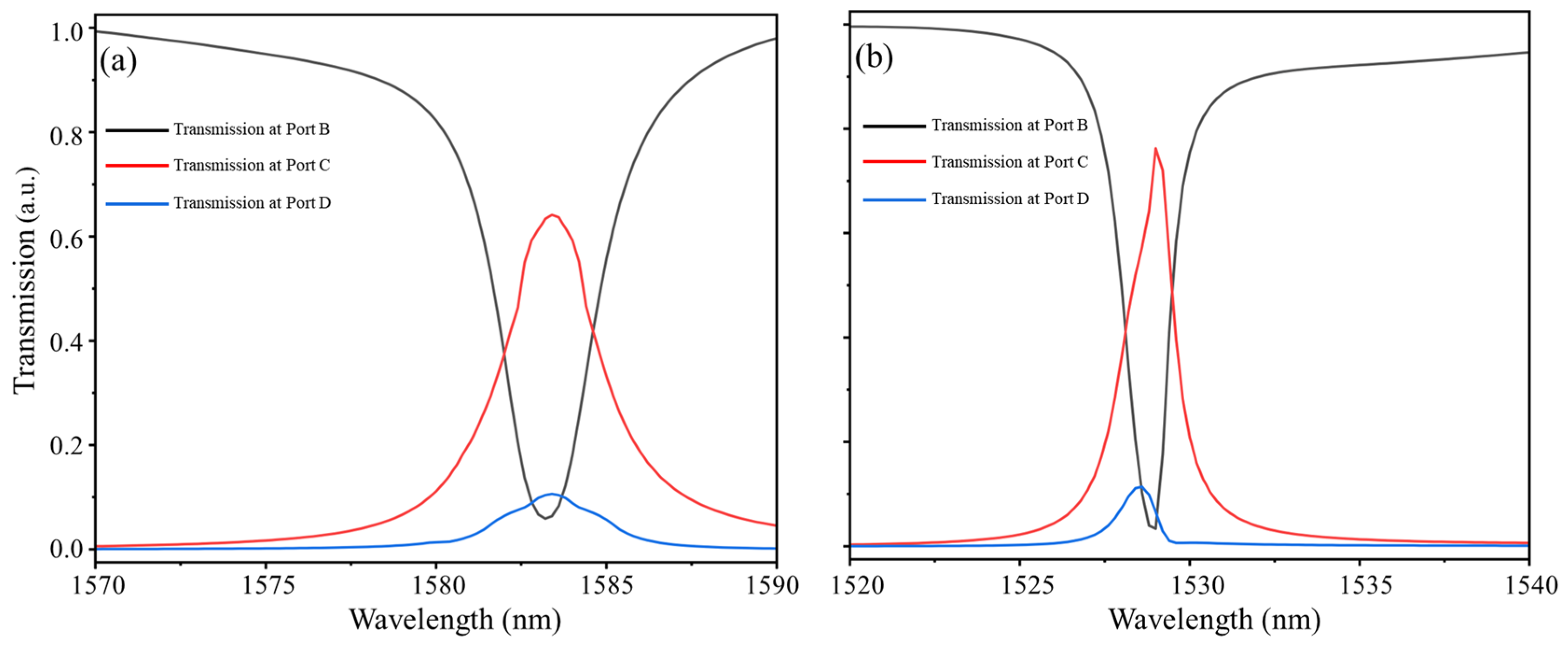
In order to investigate the effect of structural parameters on the performance of the CDF, we vary the three structural parameters a, n and Rb, respectively. The effect of different structural parameters on the spectra at port C and the resonant wavelength of the CDF are shown in Figure 5. Figure 5a reveals that a change in a has an impact on the resonant wavelength. When a changes from 631 to 639, the corresponding resonant wavelength shifts from λ = 1534.3 nm to 1536.7 nm. During this process, there are significant changes in the transmittance and FWHM, with perfect performance observed only when a = 635 nm. Figure 5b shows that when n is increased from 3.88 to 3.92, the resonant wavelength shifts from 1525.8 nm to 1542.9 nm. The overall transmittance fluctuates significantly, with a significant decrease of only about 70% compared to other situations when n is 3.88 and 3.89. However, the changes in FWHM and Q factor are not significant. When the radius Rb is increased from 605 nm to 610 nm, the resonant wavelength shifts from 1531.4 nm to 1541.9 nm, as shown in Figure 5c. The transmittance fluctuates greatly under different Rb, but there is a transmittance of over 90% between 607 nm and 610 nm. Meanwhile, with an increase in Rb, an increase in FWHM leads to a corresponding decrease in the Q factor value. The relationship between different parameters and the resonant wavelength is almost a straight line, as can be seen in Figure 5a1–c1, except for when a moves from 631 nm to 633 nm, where the central wavelength exhibits a faster rate of displacement.
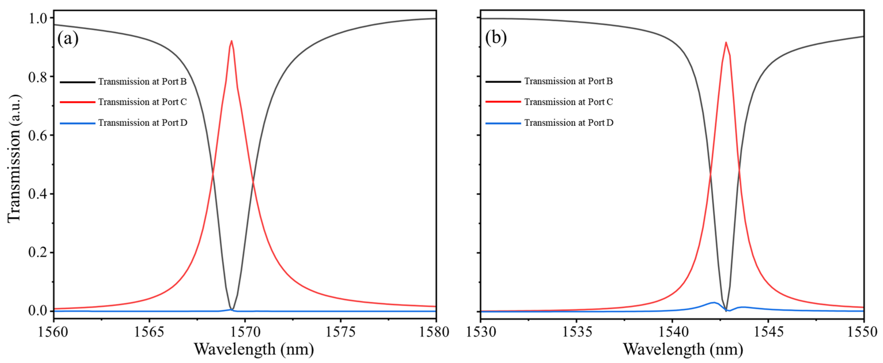
During the process of fabricating photonic crystals, inevitable errors always occur. Therefore, research on the robustness of the performance to fabrication tolerance is essential. We discuss the performance when the radius of the integral dielectric column of the device changes by ±15 nm and ±10 nm.
The output spectra of different integral radii (±15 nm and ±10 nm) are shown in Figure 6 and Figure 7. It can be seen that the filtering performance of the radius within ±15 nm is not satisfactory, with the transmittance only about 60% and 75%. However, when the integral radius varies by ±10 nm, the transmittance reaches over 90%, and the filtering performance is favorable at this time. Therefore, when considering the robustness of the performance to fabrication tolerance, the proposed filter maintains a preferable filtering performance within a range of ±10 nm as the integral radius changes, and filtering artifacts are also evident within a range of ±15 nm. In the actual processing process, in addition to the nanoscale changes in the device, environmental factors and manufacturing processes can also affect the performance of the filter.

3. Description of the Optimal Three-Channel Filter

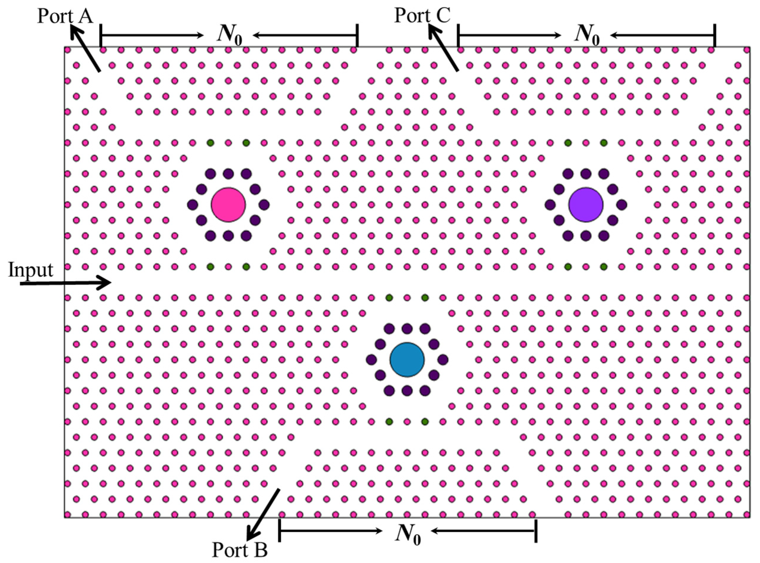
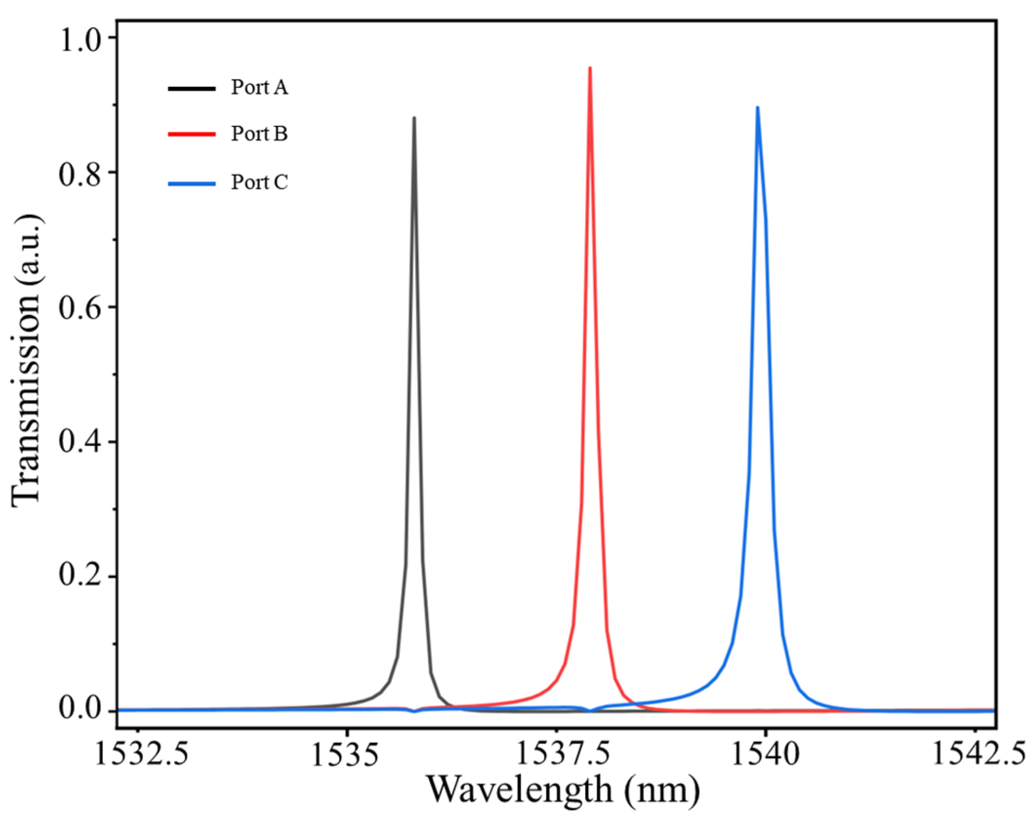
Based on the study of the above single resonant cavity, the enhanced three-channel CDF configuration is obtained by cascading three basic units, which is shown in Figure 8. The cascaded filter consists of three cavities, one main input waveguide and three output waveguides that export from port A, port B and port C, with a high coupling efficiency between the waveguides and the ring cavities for wavelength selection. The large dielectric rods inside the three-ring cavity have different Rb values of 607 nm, 608 nm and 609 nm, respectively. The number of dielectric rods N0 between the output port and idle port is 15, and the corresponding output spectra are shown in Figure 9. The transmittances and the Q factors at ports A, B and C are 88.06%, 95.46% and 89.59% and 12,780, 10,252 and 7333, respectively.
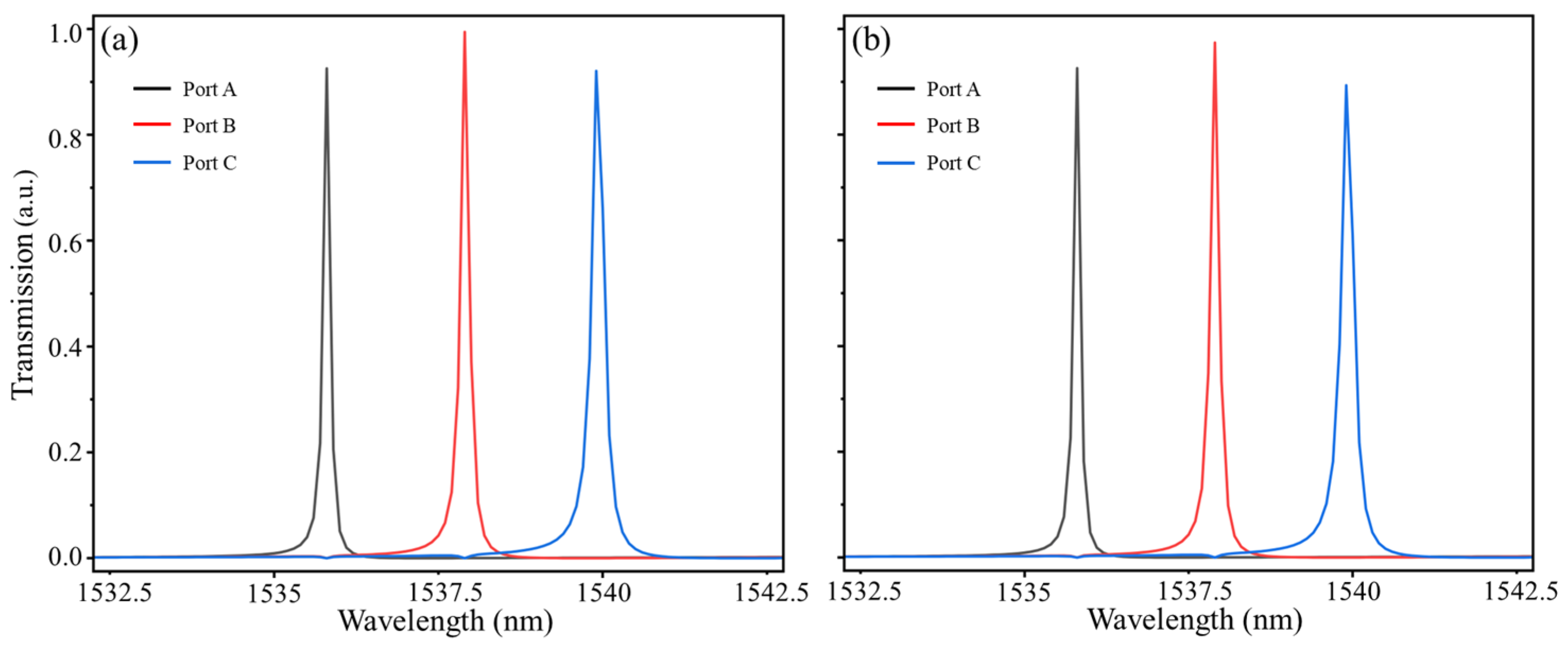
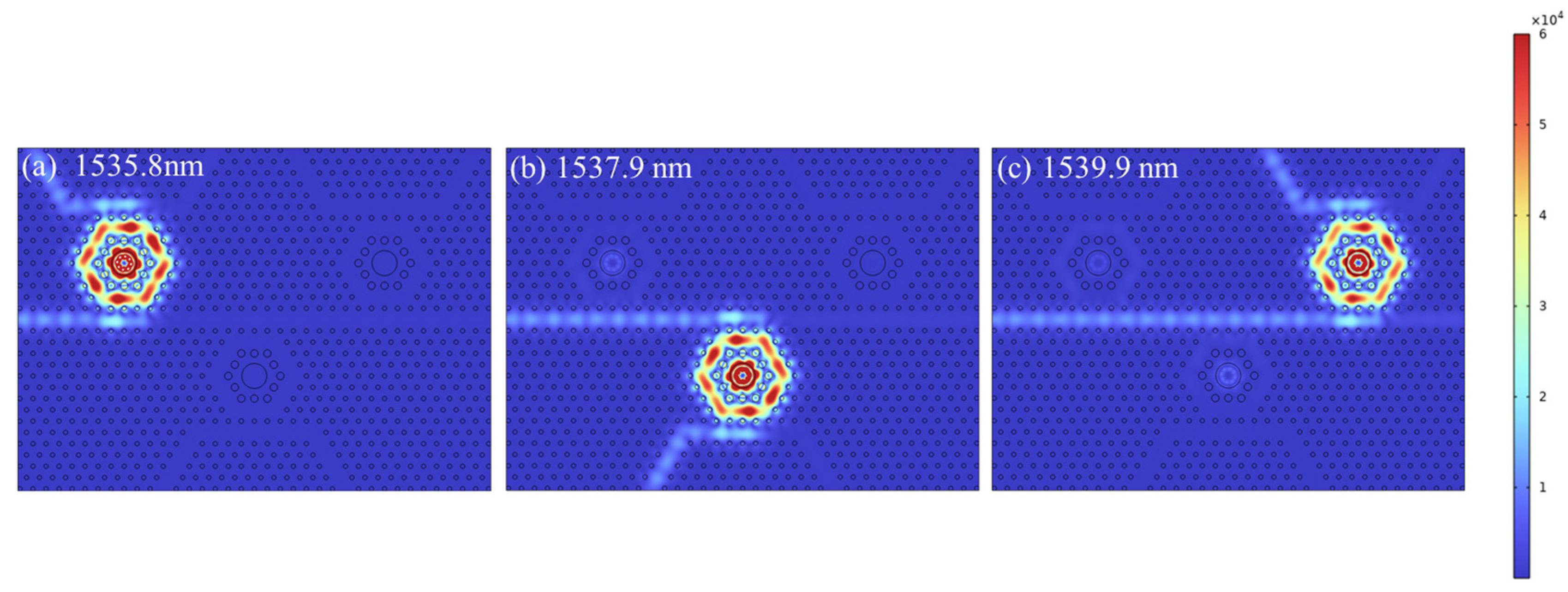
By adjusting N0 and comparing the performance with different structures, the three-channel CDF structure can be optimized. The output spectra at N0 = 13 and N0 = 11 are shown in Figure 10. When N0 = 11, the transmittances at the output port are 92.54%, 97.43% and 89.34%, respectively. The transmittances and the Q factors are 92.55%, 99.44% and 92.07% and 13,354, 10,985 and 7512, respectively, when N0 = 13. As a result, the optimized three-channel CDF is achieved at N0 = 13 with resonant wavelengths of 1535.8 nm, 1537.9 nm and 1539.9 nm. The distribution of the electric fields diagram is shown in Figure 11.
The output spectra on a dB scale are illustrated in Figure 12. From the figure, the spectra show an asymmetric profile with several valleys. The spectra at port B and port C have valleys at the same wavelength as the resonant wavelength of the first cavity, while the spectrum at port C has a valley at the same wavelength as the resonant wavelength of the second cavity, which is attributed to a significant decrease in transmittance when light passes through the other ring resonators. The crosstalk values, denoted as Xij (i, j ranges from 1 to 3), between various channels are listed in Table 2, with the definition of X = 10 lg(Pat/Pt), where Pt and Pat are the power at the output channel and the power at the other channels. From Table 2, the highest crosstalk value is −30.16 dB, while the lowest crosstalk value is −50.61 dB, which indicates a high degree of isolation.
By discussing the output spectra and the crosstalk of the proposed CDFs, the performance of high transmission, high Q factor and low crosstalk could be accurately obtained. The optimal transmittances of the high-efficiency three-channel CDF are 92.55%, 99.44% and 92.07%, with Q factors of 13,354, 10,985 and 7512. Meanwhile, the channel crosstalk between −50.61 dB and −30.16 dB is acquired by changing the number of dielectric rods between the output port and idle port waveguides. In addition, the device includes only three resonators and main waveguides with an area of only 312.62 μm2, which greatly scales down the size of the integrated device.
A comparison of the performance parameters of the designed multi-channel CDFs with those of other existing multi-channel filters is listed in Table 3. The proposed CDFs rely on a circular resonant cavity with a dielectric rod arranged with a large radius to replace the uniformly arranged dielectric columns inside the ring cavity and to modulate the coupling ratio between the straight waveguide and the ring cavity to improve the coupling efficiency, ultimately achieving a high Q factor and high transmittance filtering function.

4. The Scalability Analysis

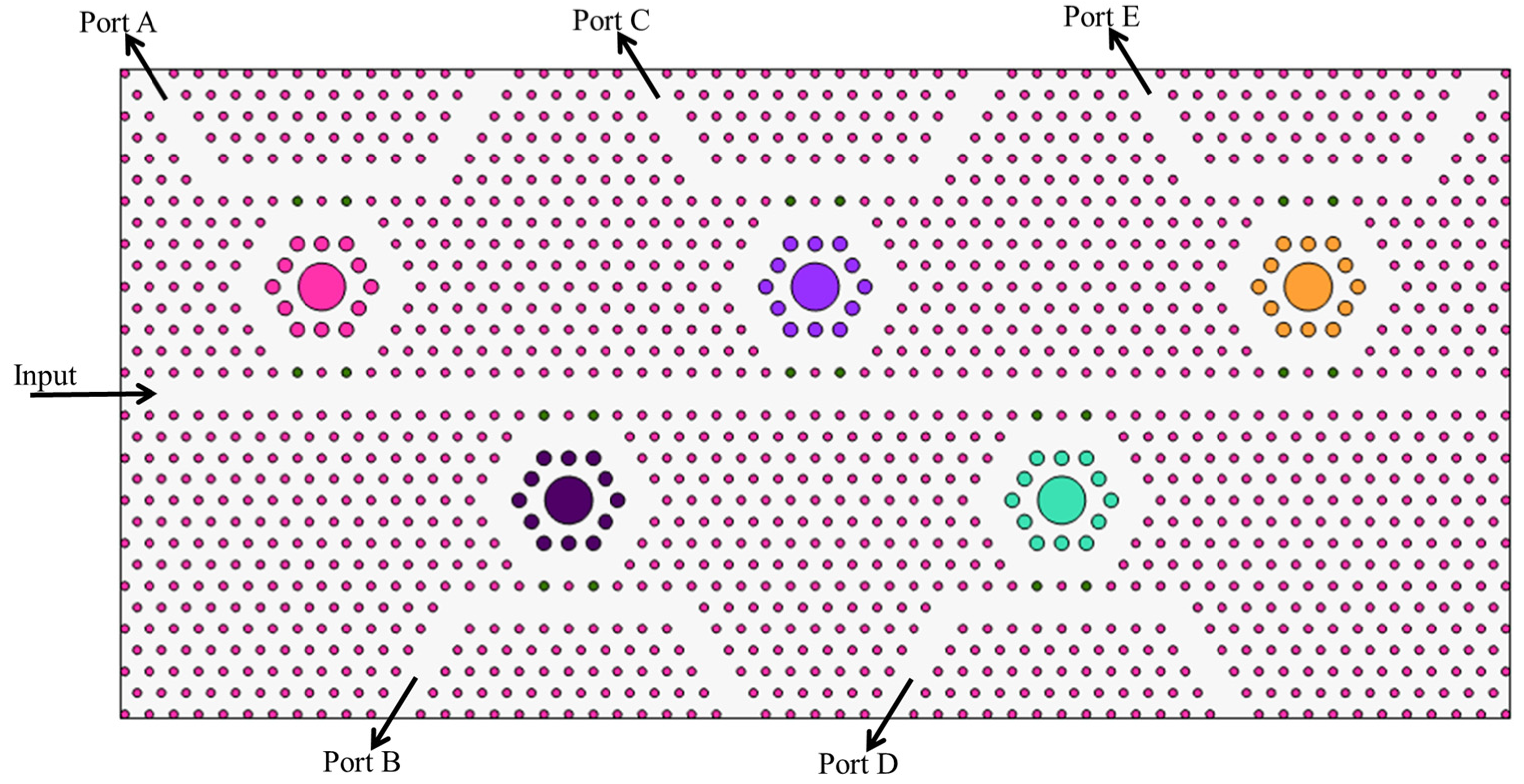
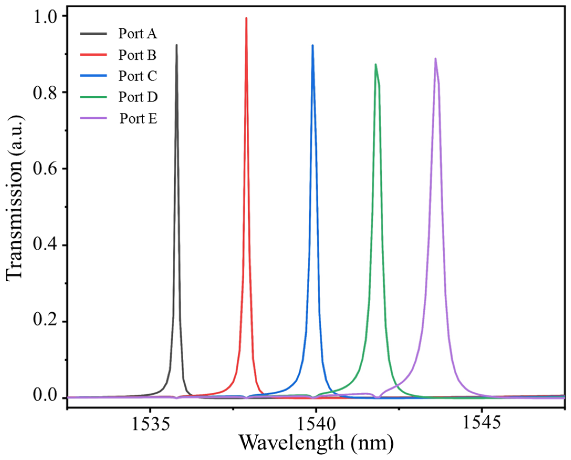
Based on the simplicity and miniaturization characteristics of the cavity structure, expanding the three-channel CDF is a straightforward process. For the sake of simulation accuracy and duration, we analyze the structure extended to a five-channel structure in this section. By changing the radius of the dielectric rod Rb, a new five-channel CDF structure with five output wavelengths is obtained, as shown in Figure 11, and the corresponding output spectrum is shown in Figure 13.
As shown in Figure 14, the transmission efficiencies and the Q factors of the structure in the five-channel filter still reaches 92.13%, 99.37%, 92.28%, 88.28% and 89.77% and 10,970, 10,252, 7897, 5818 and 4411, respectively. The average interval between the five wavelengths is 2 nm, indicating strong scalability.

5. Conclusions

In this paper, a three-channel CDF applying ring resonators is proposed to obtain a high transmission efficiency and a high Q factor. Based on the dielectric columns inside the ring resonant cavity, a particular ring resonator arranged as a dielectric rod with a large radius structure is introduced to trap light efficiently and to add certain scattering nanorods inside the cavity to reduce light scattering, thus enhancing the transmission and Q factor. By discussing the influence of different numbers of dielectric rods between the output port and idle port, we optimized the structure of the three-channel CDF. The results show that the proposed single-channel CDF has 99.7% transmittance and a Q factor of 12798.4. The three-channel CDF achieves high transmission efficiencies of 92.55%, 99.44% and 92.07%, high Q factors of 13,354, 10,985 and 7512 and channel crosstalks between −50.61 dB and −30.16 dB. The proposed PhC CDFs have remarkable performance and ensure minimal interference between optical signals of different wavelengths during transmission, which could facilitate frequency-division multiplexing and wavelength-division multiplexing, and they have potential applications in optical communication systems.

Author Contributions

Conceptualization, X.Y. and A.Z.; methodology, X.Y. and A.Z.; software, X.Y.; validation, X.Y., A.Z. and J.W.; investigation, X.Y.; data curation, X.Y.; funding acquisition, A.Z.; investigation, X.Y.; methodology, X.Y.; supervision, X.Y., A.Z. and J.W.; writing—original draft, X.Y.; writing—review and editing, X.Y., A.Z. and J.W. All authors have read and agreed to the published version of the manuscript.

Funding

This work was supported by the Key Project of Tianjin Natural Science Foundation (No.20JCZDJC00500).

Institutional Review Board Statement

Not applicable.

Informed Consent Statement

Not applicable.

Data Availability Statement

Data are contained within the article.

Conflicts of Interest

The authors declare no conflicts of interest.

References

  1. Yablonovitch, E. Inhibited spontaneous emission in solid-state physics and electronics. Phys. Rev. Lett. 1987, 58, 2059–2062. [Google Scholar] [CrossRef]
  2. Plihal, M.; Maradudin, A.A. Photonic band structure of two-dimensional systems: The triangular lattice. Phys. Rev. B 1991, 44, 8565–8571. [Google Scholar] [CrossRef] [PubMed]
  3. John, S. Strong localization of photons in certain disordered dielectric superlattices. Phys. Rev. Lett. 1987, 58, 2486–2489. [Google Scholar] [CrossRef] [PubMed]
  4. Su, J.-Y.; Huang, X.-Q.; Xu, H.-L.; Zhou, J.-Y.; Meng, Z.-M. Ultrafast all-optical switching in a silicon-polymer compound slotted photonic crystal nanobeam cavity. Opt. Rev. 2023, 30, 33–40. [Google Scholar] [CrossRef]
  5. Gupta, P.K.; Paltani, P.P.; Tripathi, S. Pressure sensor based on two-dimensional photonic crystal ring resonator. Phys. Scr. 2023, 98, 125522. [Google Scholar] [CrossRef]
  6. Ghadrdan, M.; Mansouri-Birjandi, M.A. Concurrent implementation of all-optical half-adder and AND & XOR logic gates based on nonlinear photonic crystal. Opt. Quantum Electron. 2013, 45, 1027–1036. [Google Scholar]
  7. Al-Hawary, S.I.S.; Alkhayyat, A.; Shafieezadeh, M.M.; Dwijendra, N.K.A.; Khalaf, E.; Muda, I. A novel microstructure of 2-bit optical analog to digital converter based on kerr effect nonlinear nanocavities in 2D photonic crystal. J. Sens. 2023, 2023, 5795945. [Google Scholar] [CrossRef]
  8. Jervakani, A.T.; Darki, B.S. An ultracompact optical polarizer based on the one-dimensional photonic crystals containing anisotropic layers. Opt. Commmun. 2023, 526, 128884. [Google Scholar] [CrossRef]
  9. Wu, F.; Chen, M.; Xiao, S. Wide-angle polarization selectivity based on anomalous defect mode in photonic crystal containing hyperbolic metamaterials. Opt. Lett. 2022, 47, 2153–2156. [Google Scholar] [CrossRef]
  10. She, Y.; Liu, D.; Li, J.; Yao, M.; Zheng, Y.; Wu, F. Tunable wide-angle high-efficiency polarization selectivity based on a one-dimensional photonic crystal containing elliptical metamaterials. Phys. Lett. A 2024, 494, 129299. [Google Scholar] [CrossRef]
  11. Alagappan, G.; Wu, P. Design of sharp transmission filters using band-edge resonances in one-dimensional photonic crystal hetero-structures. Appl. Phys. B 2009, 96, 709–713. [Google Scholar] [CrossRef]
  12. Li, L.; Liu, G.Q. Photonic crystal ring resonator channel drop filter. Opt. Int. J. Light Electron Opt. 2013, 124, 2966–2968. [Google Scholar] [CrossRef]
  13. Kang, M.; Jin, H.; Jeon, H. Photonic crystal L3 cavity laser fabricated using maskless digital photolithography. Nanophotonics 2022, 11, 2283–2291. [Google Scholar] [CrossRef]
  14. Geiss, R.; Diziain, S.; Steinert, M.; Schrempel, F.; Kley, E.; Tünnermann, A.; Pertsch, T. Photonic crystals in lithium niobate by combining focussed ion beam writing and ion-beam enhanced etching. Phys. Status Solidi A 2014, 211, 2421–2425. [Google Scholar] [CrossRef]
  15. Saha, N.; Brunetti, G.; di Toma, A.; Armenise, M.N.; Ciminelli, C. Silicon Photonic Filters: A Pathway from Basics to Applications. Adv. Photonics Res. 2024, 2024, 2300343. [Google Scholar] [CrossRef]
  16. Liu, K.; Jin, N.; Cheng, H.; Chauhan, N.; Puckett, M.W.; Nelson, K.D.; Behunin, R.O.; Rakich, P.T.; Blumenthal, D.J. Ultralow 0.034 dB/m loss wafer-scale integrated photonics realizing 720 million Q and 380 μW threshold Brillouin lasing. Opt. Lett. 2022, 47, 1855–1858. [Google Scholar] [CrossRef]
  17. Saha, N.; Brunetti, G.; Armenise, M.N.; Ciminelli, C. Tunable narrow band add-drop filter design based on apodized long period waveguide grating assisted co-directional coupler. Opt. Express 2022, 30, 28632–28646. [Google Scholar] [CrossRef] [PubMed]
  18. Zhu, T.; Hu, Y.; Gatkine, P.; Veilleux, S.; Bland-Hawthorn, J.; Dagenais, M. Arbitrary on-chip optical filter using complex waveguide Bragg gratings. Appl. Phys. Lett. 2016, 108, 101104. [Google Scholar] [CrossRef]
  19. Gatkine, P.; Veilleux, S.; Hu, Y.; Bland-Hawthorn, J.; Dagenais, M. Arrayed waveguide grating spectrometers for astronomical applications: New results. Opt. Express 2017, 25, 17918–17935. [Google Scholar] [CrossRef]
  20. Takada, K.; Abe, M.; Shibata, T.; Okamoto, K. 10-GHz-spaced 1010-channel tandem AWG filter consisting of one primary and ten secondary AWGs. IEEE Photonic Technol. Lett. 2001, 13, 577–578. [Google Scholar] [CrossRef]
  21. Dai, D.; He, S. Highly sensitive sensor based on an ultra-high-Q Mach-Zehnder interferometer-coupled microring. J. Opt. Soc. Am. B 2009, 26, 511–516. [Google Scholar] [CrossRef]
  22. Chergui, I.; Bounaas, F.; Labbani, A. Novel design of four-channel wavelength division demultiplexer based on two-dimensional photonic crystal ring resonators. In Proceedings of the 2022 International Conference of Advanced Technology in Electronic and Electrical Engineering (ICATEEE), M’sila, Algeria, 26–27 November 2022; pp. 1–4. [Google Scholar]
  23. Dhandrapati, L.; Tupakula, S. A novel 8-channel DWDM demultiplexer on silicon photonic crystal slab: Design and analysis. Optik 2022, 256, 168734. [Google Scholar] [CrossRef]
  24. Al Dujaili, M.J.; Abed, N.H. Design a Photonic Crystal Narrowband Band Pass Filter at a Wavelength of 1570 nm for Fiber Optic Communication Applications. Wirel. Pers. Commun. 2023, 131, 877–886. [Google Scholar] [CrossRef]
  25. Chanu, S.A.; Sonkar, R.K. High coupling efficiency photonic crystal waveguide for compact channel drop filter design on silicon-on-insulator platform. Opt. Eng. 2023, 62, 087101. [Google Scholar] [CrossRef]
  26. Olivier, S.; Benisty, H.; Weisbuch, C.; Smith, C.J.M.; Krauss, T.F.; Houdré, R. Coupled-mode theory and propagation losses in photonic crystal waveguides. Opt. Express 2003, 11, 1490–1496. [Google Scholar] [CrossRef] [PubMed]
  27. Adachi, S. Optical dispersion relations for GaP, GaAs, GaSb, InP, InAs, InSb, AlxGa1−xAs, and In1−xGaxAsyP1−y. J. Appl. Phys. 1989, 66, 6030–6040. [Google Scholar] [CrossRef]
  28. Guo, S.; Albin, S. Simple plane wave implementation for photonic crystal calculations. Opt. Express 2003, 11, 167–175. [Google Scholar] [CrossRef]
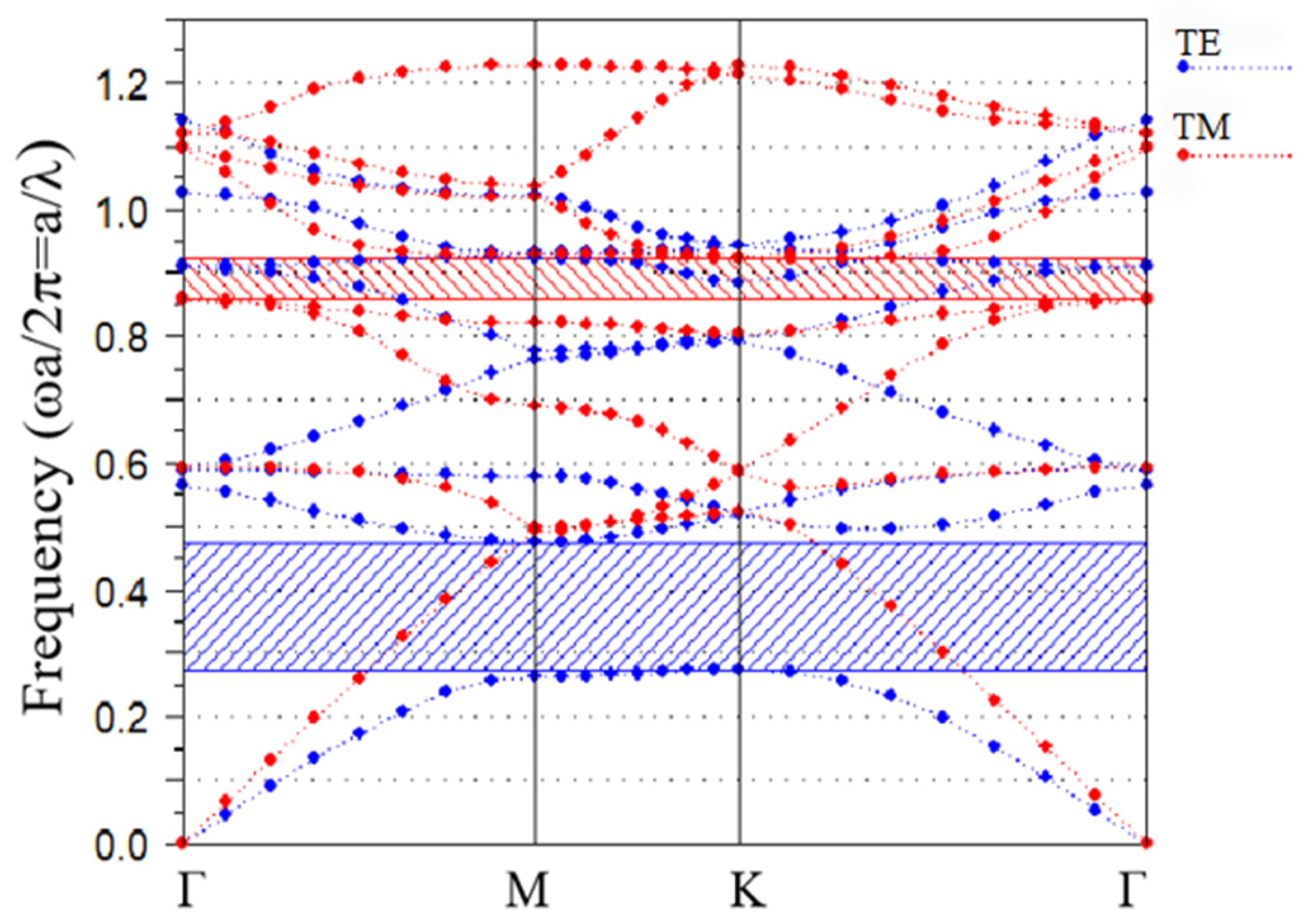
Figure 1. Band structure of the GaSb photonic crystal.
Photonics 11 00554 g001
Figure 2. Diagram of the CDF. (a) Macroscopic view of the configuration and (b) the ring resonator inside the cavity.
Photonics 11 00554 g002
Figure 3. Normalized output spectrum of the CDF.
Photonics 11 00554 g003
Figure 4. Distribution of the electric field at (a) 1530 nm and (b) 1535.8 nm.
Photonics 11 00554 g004
Figure 5. Effect of different parameters on the output spectra and the resonant wavelength. (a,a1) a. (b,b1) n. (c,c1) Rb.
Photonics 11 00554 g005
Figure 6. The output spectra of different integral radii. (a) +15 nm and (b) −15 nm.
Photonics 11 00554 g006
Figure 7. The output spectra of different integral radii. (a) +10 nm and (b) −10 nm.
Photonics 11 00554 g007
Figure 8. Schematic of the three-channel filter.
Photonics 11 00554 g008
Figure 9. Output spectra when N0 = 15.
Photonics 11 00554 g009
Figure 10. Output spectra with different structures. (a) N0 = 13 and (b) N0 = 11.
Photonics 11 00554 g010
Figure 11. Distribution of the electric fields at (a) 1535.8 nm, (b) 1537.9 nm and (c) 1539.9 nm.
Photonics 11 00554 g011
Figure 12. Output spectra of the three-channel filter on a dB scale.
Photonics 11 00554 g012
Figure 13. Schematic of the five-channel filter.
Photonics 11 00554 g013
Figure 14. Output spectra of the five-channel filter.
Photonics 11 00554 g014
Table 1. The structural parameters of the CDF in the simulation.
ParameterIllustrationValue
aLattice constant635 nm
nCommon dielectric rods refractive index3.9
n0Air refractive index1
rCommon dielectric rods radius106 nm
RIntracavity light-green dielectric rods radius180 nm
RbIntracavity dark-green large dielectric rods radius607 nm
RcScattering dielectric rods radius115 nm
Table 2. The calculated values of crosstalk of the three-channel filter.
Xij (dB)Port APort BPort C
Port A——−48.80−50.61
Port B−38.10——−40.28
Port C−30.16−45.71——
Table 3. Comparison of our CDFs with those of other works.
Ref.Cavity ShapeTransmittance (%)Q FactorAverage
Transmittance (%)
Average Q Factor
[22]Octagonal ring cavity99.93883.299.451613 (four-channel)
[23]Regular hexagonal ring cavity50500070.45150 (eight-channel)
[24]Nested circular ring cavity97.44268————
[25]Line defect cavity————88.04783 (three-channel)
ProposedA dielectric column with large radius inside hexagonal ring resonator99.712,798.494.610,617 (three-channel)
Disclaimer/Publisher’s Note: The statements, opinions and data contained in all publications are solely those of the individual author(s) and contributor(s) and not of MDPI and/or the editor(s). MDPI and/or the editor(s) disclaim responsibility for any injury to people or property resulting from any ideas, methods, instructions or products referred to in the content.