Article

High-Repetition-Rate 2.3–2.7 µm Acousto-Optically Tuned Narrow-Line Laser System Comprising Two Master Oscillators and Power Amplifiers Based on Polycrystalline Cr2+:ZnSe with the 2.1 µm Ho3+:YAG Pulsed Pumping

1
Institute of Applied Physics, Russian Academy of Sciences, 603950 Nizhny Novgorod, Russia
2
Higher School of General and Applied Physics, Lobachevsky State University of Nizhny Novgorod, 603022 Nizhny Novgorod, Russia
3
Institute of Chemistry of High-Purity Substances, Russian Academy of Sciences, 603951 Nizhny Novgorod, Russia
4
Department of Material Science, Nizhny Novgorod State Technical University, 603950 Nizhny Novgorod, Russia
5
Department of Quantum Electronics and Photonics, National Research Tomsk State University, 634050 Tomsk, Russia
*
Author to whom correspondence should be addressed.
Photonics 2024, 11(6), 555; https://doi.org/10.3390/photonics11060555
Submission received: 30 April 2024 / Revised: 24 May 2024 / Accepted: 29 May 2024 / Published: 12 June 2024

Abstract

:
High-average-power narrow-linewidth tunable solid-state lasers in the wavelength region between 2 and 3 μm are attractive light sources for many applications. This paper reports a narrow-linewidth widely tunable laser system based on the polycrystalline Cr2+:ZnSe elements pumped by repetitively pulsed 2.1 µm Ho3+:YAG laser operating at a pulse rate of tens of kilohertz. An advanced procedure of ZnSe element doping and surface improvement was applied to increase the laser-induced damage threshold, which resulted in an increase in the output power of the Cr2+:ZnSe laser system. The high-average-power laser system comprised double master oscillators and power amplifiers: Ho3+:YAG and Cr2+:ZnSe laser oscillators, and Ho3+:YAG and Cr2+:ZnSe power amplifiers. The output wavelength was widely tuned within 2.3–2.7 µm by means of an acousto-optical tunable filter inside a Cr2+:ZnSe master oscillator cavity. The narrow-linewidth operation at the pulse repetition rate of 20–40 kHz in a high-quality beam with an average output power of up to 9.7 W was demonstrated.

1. Introduction

High average power tunable solid-state lasers in the wavelength range from 2 to 3 μm are attractive light sources for many applications, such as medical surgery and lasertripsy, laser processing, environmental remote sensing, wireless energy transmission technology, pumping mid-infrared optical parametric oscillators, and solid-state lasers based on Fe2+-doped crystals [1,2,3,4,5,6,7,8,9,10,11]. Cr2+-doped zinc selenide (Cr2+:ZnSe) crystals are among the most attractive active media for high-average power lasers in the 2–3 µm wavelength range due to their wide tunability, broad absorption bands, and large stimulated-emission cross section [12,13,14,15,16,17,18,19,20]. The gain-switched operation in nanosecond pulse mode of the Cr2+:ZnSe lasers and a wide wavelength tuning of their outputs were previously reported [18,19,21,22,23,24,25,26,27,28,29,30,31,32,33,34,35,36]. Various wavelength tuning techniques have been used in Cr2+:ZnSe lasers: intracavity wavelength-selective elements such as diffraction gratings [18,19,21,27,28], birefringent Liot filters [24,30], prisms [31,32], acousto-optic tunable filters (AOTFs) [22,23,25,26,29,33,34], liquid crystal etalon [35], or injection seeding [36]. The AOTF wavelength tuning is one of the most attractive technique: the AOTF enabled the laser to electronically tune every pulse in the broad-wavelength tuning range [37]. In the narrow-line widely tunable Cr2+:ZnSe laser systems pumped by the Tm3+:YAP lasers, two pulsed regimes were reported: the pulse energy of up to 50 mJ in a slow pulse regime at a pulse repetition rate (PRR) of 10 Hz [26], or the average power of up to 5.1 W in a faster operating regime at 7 kHz PRR [23]. However, the scaling of the average and peak power and the pulse energy of the laser systems is hindered by the laser-induced damage (LID) of both polycrystalline and single-crystalline Cr2+:ZnSe [19,22,23,26,38,39,40,41].
In this paper, we present a high-average-power high-PRR AOTF-tunable solid-state laser system based on the polycrystalline Cr2+:ZnSe pumped at 2091 nm by the repetitively pulsed fiber-laser-pumped Ho3+:YAG lasers. The laser system architecture comprised a tunable Cr2+:ZnSe master oscillator and Cr2+:ZnSe power amplifier pumped with 10–40 kHz PRR by a Ho3+:YAG master oscillator and a Ho3+:YAG power amplifier, respectively. An intracavity AOTF provided a 2.3–2.7 μm tunability of the narrow-band generation of the Cr2+:ZnSe laser pulses. An advanced procedure of Cr2+:ZnSe element doping and surface improvement was applied to increase the LID threshold, which resulted in an increase in the output power of the Cr2+:ZnSe laser system.

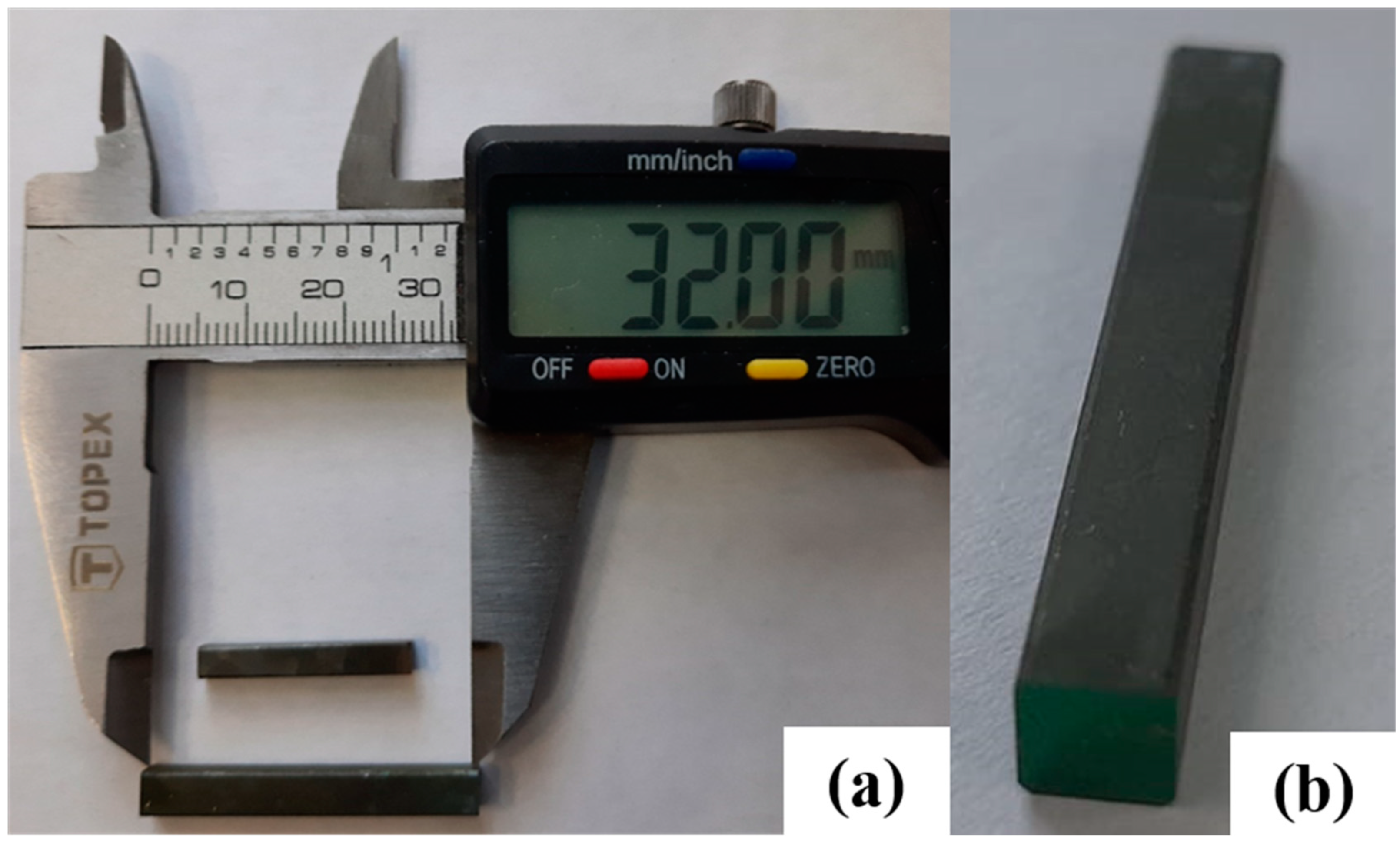
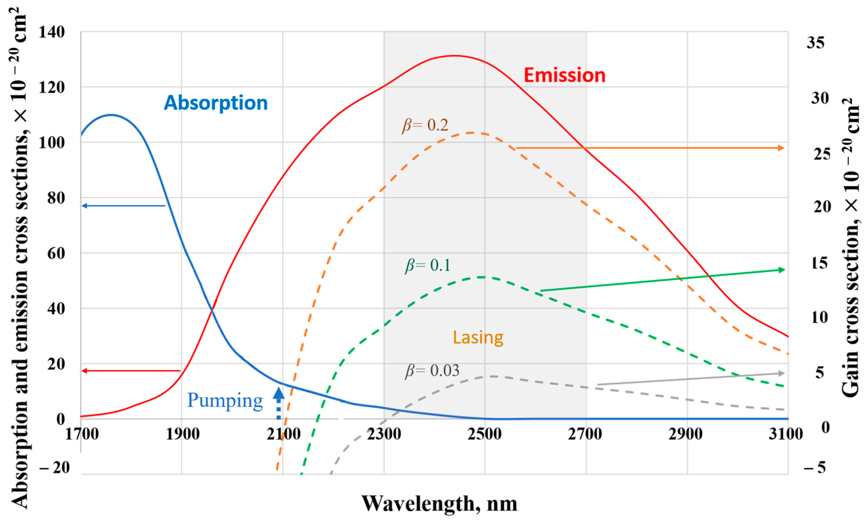
2. Cr2+:ZnSe Active Elements

The Cr2+:ZnSe active elements were made from laser-quality zinc selenide (ZnSe) obtained by means of chemical vapor deposition (CVD) and cut into blanks with a cross section of up to 4.5 × 4.5 mm2. The length of the blanks, and thus of the laser elements, varied from 15 mm to 33 mm. A chromium film was vacuum-deposited on the side surface of the blanks [15]. Subsequently, the samples were placed in a quartz ampoule, washed with high purity argon, and vacuumed 5 times. Metallic zinc (Zn) was also added to the ampoule; the amount of zinc was adjusted to equalize the Zn vapor pressure at the annealing temperature to atmospheric pressure. The ampoule was vacuumed, sealed, and held in a muffle furnace at 1050 °C for 7 days. The ampoule was then unsealed and the elements were processed in a hot isostatic press for 20 h at 1100 °C in argon to restore the ZnSe stoichiometry (to remove excess Zn). In preliminary testing, the highest LID threshold was found in Cr2+:ZnSe samples annealed in argon (Ar) atmosphere compared to samples annealed in Zn atmosphere or with hot isostatic pressing [40,42]. However, annealing in a sealed ampoule does not provide confidence that the stoichiometry of the material has been restored. In this work, hot isostatic pressing was used, but compared to the procedure described in [40], the samples were placed in a graphite container to reduce contamination. As a result of this doping procedure, chromium ions (Cr2+) were uniformly distributed throughout the sample volume and the elements had an increased LID threshold. The side surfaces of the samples were finely ground to prevent stray reflections and to reduce the probability of parasitic generation; all right angles were chamfered at ~0.2 mm.
The Cr2+-ion doping concentration (Nd) and element length (L) were chosen so that the single-pass small-signal absorption coefficient (αabs × L = σabs × Nd × L, where σabs is the absorption cross section) of the Cr2+:ZnSe element at 2091 nm was in the range of 1–1.5. The Cr2+-ion doping concentration was kept low to avoid strong thermal aberrations in the active elements. The length of Cr2+:ZnSe elements was optimized based on the preliminary absorption measurements; the final length of the active elements with different Cr2+-ion doping concentration was in the range of 14 to 32 mm. Assuming the absorption cross section of Cr2+:ZnSe at 2091 nm of σabs = 1.4 × 10⁻¹⁹ cm2 [12,19], the final concentration of the Cr2+ ions in the laser elements was estimated to be Nd = 3–6 × 1018 cm−3.
The cross section of the active element was 3 × 3 mm2 or 3.5 × 3.5 mm2 in the 14–20 mm long samples, and 4 × 4 and 4.3 × 4.3 mm2 in the longer active elements. A broadband (2.0–2.7 µm) antireflection coating of yttrium fluoride and zinc sulfide layers was applied on the working surfaces of the active elements. A sample active element is shown in Figure 1. The Cr2+:ZnSe active elements were wrapped in indium foil and inserted into the copper radiators with the temperature stabilized at 5 ± 0.1 °C.
The absorption spectrum of Cr2+:ZnSe crystals enables the low-quantum defect pumping of the 2.3–2.7 µm laser using a Ho3+:YAG laser at 2091 nm (Figure 2). At 2091 nm, the absorption cross section σabs of the Cr2+:ZnSe crystal is less than the emission cross section σem [12,19]. Since the Cr2+ ion in a ZnSe crystal field is a 4-level system with fast relaxation in the vibronic sublevels [12,27], the sum of the populations of the 5E upper state Nup at the 2091 nm pumping and the 5T2 ground state, Ng, effectively equals to the doping concentration of Cr2+ ions in the active sites Nda (neglecting an exited state absorption and an up-conversion). In this case, the effective gain cross section G(λ) of the crystal at a wavelength λ can be calculated for a given inversion fraction β using the following expression:
G(λ) = σem(λ) × β − σabs(λ) × (1 − β) − γ(λ)/Nda,
where β = Nup/Nda, and γ(λ) are the passive losses at a wavelength λ.
The calculation of the effective gain cross section through Exp. 1 showed an increase in the operation wavelength span of the Cr2+:ZnSe laser (where the total laser gain G(λ) × Nda × L can exceed the cavity losses) with an increase in the inversion fraction (Figure 2). However, these calculations also showed that at high pump power (when the inversion fraction exceeds 0.2), pump absorption at 2091 nm ceased (where G(λ = 2091) = 0) due to the mutual compensation of up and down transitions 5E ↔ 5T2. The Cr2+:ZnSe laser crystal can bleach at the high pump power. Therefore, the low-quantum defect pump of the Cr2+:ZnSe laser at 2091 nm demonstrated a self-limiting behavior.

3. Laser System Architecture

The laser system comprised a double master oscillator–power amplifier: a Ho3+:YAG master oscillator pumping a tunable Cr2+:ZnSe master oscillator, and a Ho3+:YAG power amplifier pumping a Cr2+:ZnSe power amplifier (Figure 3).

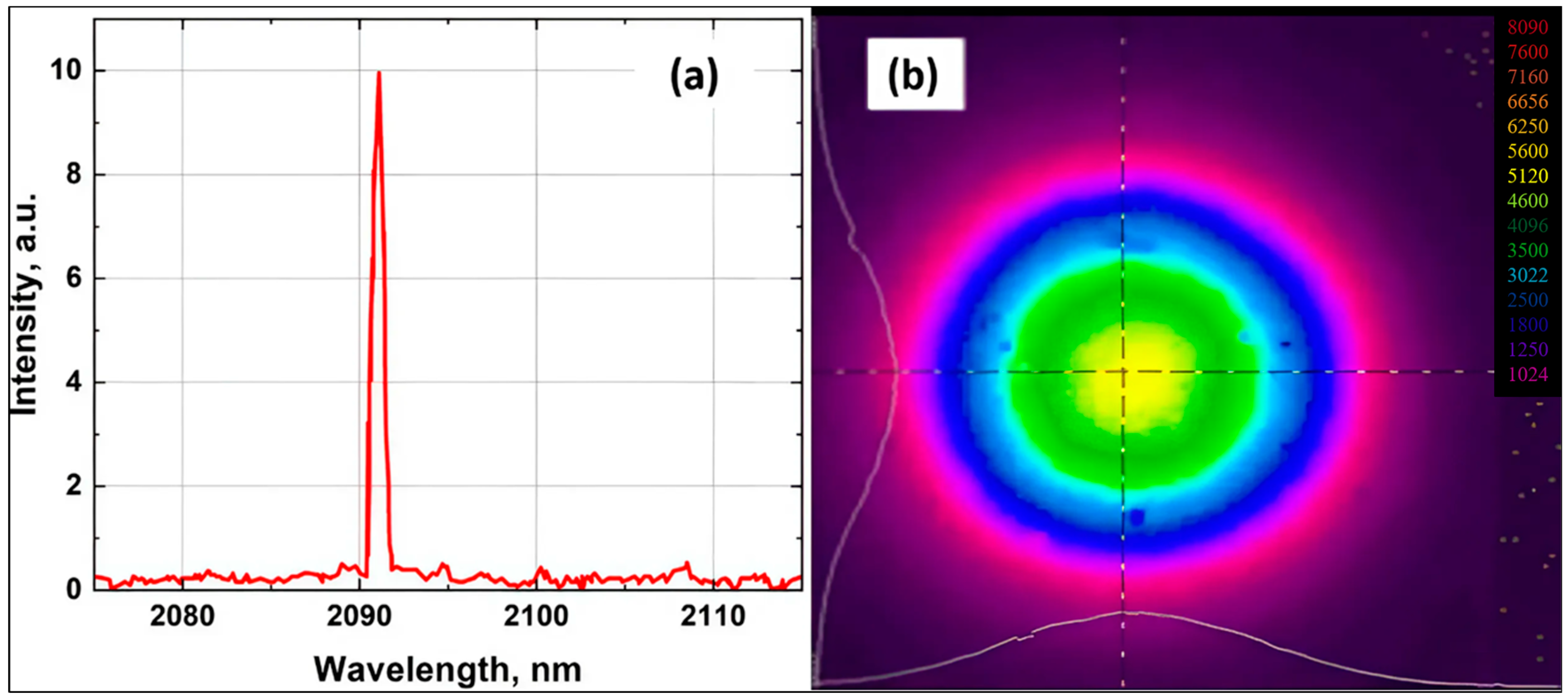
3.1. Ho3+:YAG Laser Oscillator

An in-house-made repetitively pulsed Ho3+:YAG laser at 2091 nm was used as the pump source of the Cr2+:ZnSe laser [43]. The Ho3+:YAG laser was pumped, in turn, by a CW Tm-doped fiber laser at 1908 nm (“NTO IRE-Polus”, Fryazino, Russia). The repetitively pulsed regime was achieved by active Q-switching the cavity with a quartz acousto-optical modulator (“NII Polyus”, Moscow, Russia). The operation wavelength of ~2091 nm was selected and stabilized by a rotated silica etalon of 90 µm thickness (Figure 4a). The estimated 3 dB linewidth of the Ho:YAG laser was less than 0.3 nm (the measurement accuracy was limited by the spectrometer used). The Q-switched laser operated with PRR varied from 10 to 50 kHz. The FWHM pulse width (τ) of 15–45 ns depended on the PRR and the pump power.
The average power of the Ho3+:YAG laser measured using a power meter (Coherent PM 10 with FieldMax detector, Coherent, Saxonburg, PA, USA) was up to 34 W at the 30 kHz PRR (at 55 W fiber laser pump power) in a linearly polarized high-quality Gaussian beam. The laser beam was monitored using a Pyrocam IV camera (Ophir-Spiricon, North Logan, UT, USA) (Figure 4b). The M2 parameter (determined by the ISO 11146-1:2021 standard with the knife-edge method [44]) was less than 1.2–1.3.
To avoid the influence of a back reflection on the Ho3+:YAG laser, the Faraday isolator (EOT, Traverse City, MI, USA) was used (Figure 3). A Galilean telescope (T1), a half-wavelength plate (λ/2), and a polarizer (P1) were placed in the Ho3+:YAG laser beam path; the last two optical elements controlled the power of the linearly polarized 2091 nm output and provided two polarization separation. Finally, the horizontally polarized beam from the Ho3+:YAG laser was focused into a Cr2+:ZnSe active element, but the vertically polarized beam at 2091 nm propagated to the Ho3+:YAG laser amplifier.

3.2. Ho3+:YAG Power Amplifier

The power amplifier of the beam at 2091 nm was based on Ho3+:YAG rods (“NII Polyus”, Moscow, Russia) with a length of 50 mm or 65 mm and a diameter of 5 mm or 6 mm, respectively. The Ho3+-ion concentration was 0.5 at. %. The end faces of the Ho3+:YAG rods were AR-coated at 2050–2150 nm. The Ho3+:YAG rods were wrapped in indium foil and inserted into the copper radiators, with the temperature stabilized at 5 ± 0.1 °C. The Ho3+:YAG elements were pumped by a CW Tm-doped fiber laser at 1908 nm (“NTO IRE-Polus”, Fryazino, Russia) with a power up to 53 W. The diameter of the pumping beam at 1908 nm in the Ho3+:YAG crystal was tuned by Galilean telescope T2 to be equal to ~0.8–0.9 mm, when measured at e−2 peak intensity with the knife-edge method [44]. The diameter of the repetitively pulsed amplified beam at 2091 nm was also tuned by Galilean telescope T3 to be equal to ~0.8–0.9 mm.
At a repetitively pulsed input power of 2.2 W, the maximum output power of the Ho3+:YAG amplifier based on a 50 mm long crystal was ~5.5 W. When the input power was increased to 18.1 W, the output power increased to 36 W (Figure 5a). The maximum output of the Ho3+:YAG amplifier based on a 65 mm long crystal was 7.5 W at 2.2 W input power, and with an input power of 18.1 W, the output power increased to 42 W (Figure 5b).
The decrease in gain of the 65 mm long amplifier with increasing input pulsed power can be explained by the saturation effect (Figure 6) [45]. With PRR increasing, the gain increased at low input pulsed power, but the same gain decreased at high input pulsed power (Figure 6b). The gain increase in a large signal at higher PRR can be explained by the influence of the pump-induced thermal lens and the signal self-focusing effect [46,47], which reduced the diameters of the pumping and amplified beams in the laser amplifier.
The beam quality of the amplified beam in the 65 mm rod remained high enough up to the highest power: the M2 parameter (measured using the knife-edge method [44]) was ≤1.8 at 30 W and ≤2.5 at 43 W output power (Figure 7).
The amplified beam at 2091 nm was propagated through a half-wave-plate polarization rotator (“λ/2—plate”) and dichroic mirror M4, with a high p-polarization transmission at 2091 nm and a high s-polarization reflection at 2.3–2.7 µm, before being directed into the second Cr2+:ZnSe crystal (Figure 3). The 2091 nm beam was the pumping beam of the Cr2+:ZnSe amplifier of the waves at 2.3–2.7 µm.

3.3. Cr2+:ZnSe Tunable Laser Oscillator

Multiple Cr2+:ZnSe crystals with varying lengths between 14 mm and 26 mm were tested as active elements of the laser oscillator. A part of the Ho3+:YAG laser beam was sent as the pump into the Cr2+:ZnSe laser oscillator. To avoid the LID on the Cr2+:ZnSe crystal surface, the pump energy fluence was kept under 1.5 J/cm2. For this reason, the pump beam diameter in the active element was 0.7–0.9 mm (at e−2 peak intensity) depending on the PRR, which varied from 10 to 40 kHz.
The input dichroic mirror M2 of the Cr2+:ZnSe laser cavity (Figure 3) was chosen to enable the high transmission of the p-polarized pump beam at 2091 nm and the high reflectivity of the lasing at 2.3–2.7 μm, which had an s-polarization. Rear mirror M1 had over 99% reflectivity at both the lasing wavelength of 2.3–2.7 μm and the pumping wavelength of 2091 nm. The M1 mirrors with a radius of curvature of 300 mm or 500 mm were tested in the experiments. The transmittance of output coupler M3 was varied from 30% to 70% at the lasing wavelengths. The physical cavity length was also changed from 110 to 190 mm.
An acousto-optical tunable filter (AOTF) (“NII Polyus”, Moscow, Russia) inserted into the output leg of the laser cavity provided fine wavelength tuning on the deflecting acoustic wave. The driving voltage frequency was varied from 36.5 to 43 MHz. The acousto-optical element based on the TeO2 crystal had dimensions of 4 × 4 × 25 mm3. The entrance and exit surfaces of the acousto-optical element were antireflection-coated at 2.3–2.7 µm.

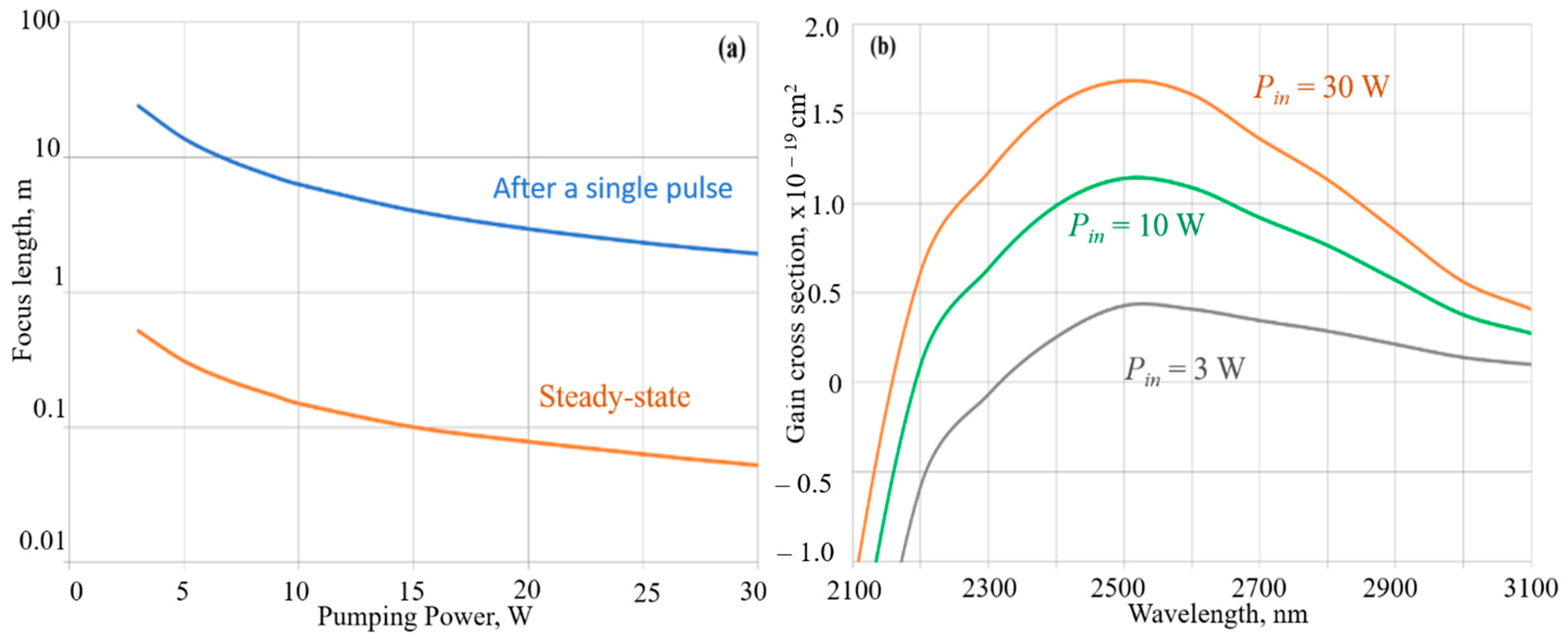
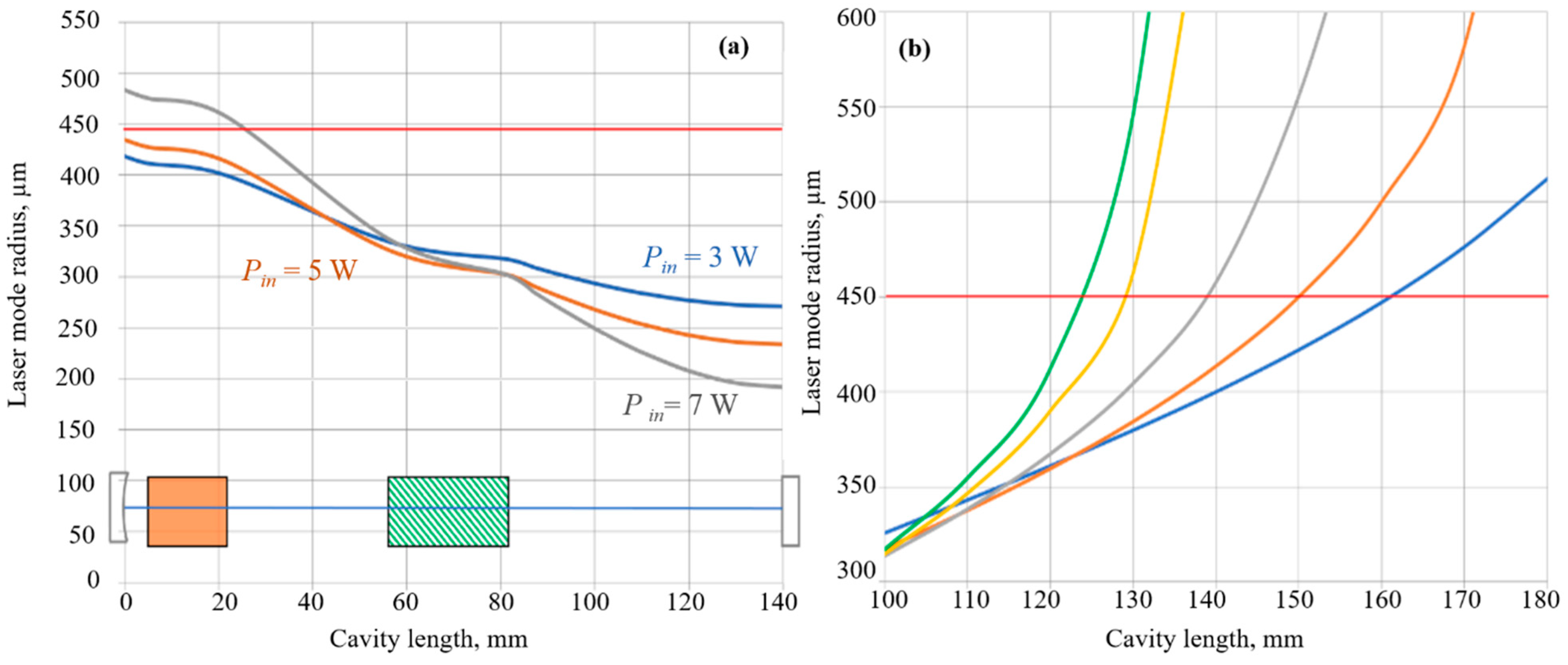
3.3.1. Numerical Simulation of the Thermal Lens and Optimization of the Cr2+:ZnSe Laser Cavity

The Cr2+:ZnSe laser cavity was numerically modelled to ensure a good overlap of a fundamental mode with the pump beam. To calculate the radius of the fundamental mode in the “hot” laser cavity, the thermal lens induced in the active element by the absorbed pump beam must be estimated.
A transient thermal lens was induced in the Cr2+:ZnSe active element under each pumping pulse. The dioptric power DT of the transient thermal lens can be estimated using the following expression [46]:
D T = 2 × n T e f f   ×   r 2 0 L T r , z , t d z r = 0 ,
where T(r,z,t) is the temperature distribution, r and z are the transverse and longitudinal coordinates, t is the time, (∂n/∂T)eff is the effective thermo-optic coefficient of the Cr2+:ZnSe crystal, including the volume coefficient (∂n/∂T), the bulging of end faces, and the photoelastic effect, and given for an active element using the well-known expression:
( n / T ) eff ( n / T ) + n 1 β T 1 + ν ,
where n is the refractive index, βT is the thermal expansion coefficient, and ν is Poisson’s ratio. The transient temperature change during each pump pulse can be estimated using
T r , z , t = σ a b s ( λ p ) ( 1 λ p λ S ) ρ c p 0 t I p ( r , z , t ) × n u p ( r , z , t ) d t = N d a σ a b s ( λ p ) ( 1 λ p λ S ) ρ c p 0 w p r , z , t d w p 1 σ a b s ( λ p ) σ a b s ( λ p ) + σ e m ( λ p ) 1 e w p σ a b s ( λ p ) + σ e m ( λ p ) h ν p ,
where σ a b s ( λ p ) and σ e m ( λ p ) are the absorption and emission cross sections at the pump wavelength λ p , νp is the pump frequency, λ s is the laser wavelength, h is the Planck constant, ρ and Cp are the density and the thermal capacity of the Cr2+:ZnSe crystal, and Ip and wp are the pump intensity and fluence. The fluence of the short pumping pulse (with the pulse width τp much less than the excited-state life time) wp(r,z,t) can be given by the Franz–Nodvig solution [45]:
w p r , z , t = h ν p σ a b s λ p + σ e m λ p ln e α a b s λ p z e w p r , 0 , t × σ a b s λ p + σ e m λ p h ν p 1 + 1 .
Expressions (2)–(5) determined the focal length of the transient thermal lens at the end of a single pulse.
The focal length of the steady-state thermal lens fT was estimated using the following expression [48,49]:
f T = π K T a p 2 P i n 1 λ p λ S δ n δ T + n 1 β T 1 + ν 1 exp σ a b s λ p L ,
where Pin is the average incident pump power with a Gaussian beam radius of ap. The other parameters of the crystal, pump beam, and laser cavity (including the TeO2 AOTF) are shown in Table 1.
The focal length of the thermal lenses at the end of each pulse (calculated using expressions (2)–(5)) and the steady-state thermal lens (calculated using expression (6)) are presented in Figure 8a.
The effective inversion fraction at the axis of the Cr2+:ZnSe active element at the end of each pumping pulse can be estimated using the following expression
β e f = 1 L 0 L n e x 0 , z , τ p N d a d z = 1 L 0 L 1 σ p σ p + σ e m p 1 e w p o , z , τ p × σ p + σ e m p h ν p d z .
Expressions (5) and (7) provide a way to estimate the inversion fraction for the average pump power at the active element input:
Pin = Wp(0) × Rrate,
where Wp(0) is the input pump pulse energy, and Rrate is the PRR. In this way, the gain cross section can be plotted for each value of the input pump power (Figure 8b).
The radius of the fundamental mode in the laser cavity with the steady-state thermal lens was calculated using the “Rezonator” software package [57]. The optimal overlap of the fundamental mode at 2400 nm and the pumping beam in the active element was achieved at a pump power of 28 W in the cavity with a physical length of 140 mm (Figure 9a). The optimal cavity length for stable mode operation decreased with the increase in the pump power (Figure 9b). Rear mirror M1 with a 300 mm radius of curvature was found to be more suitable for the used pump power and the active elements due to the good overlap of the pumping beam and the laser mode.

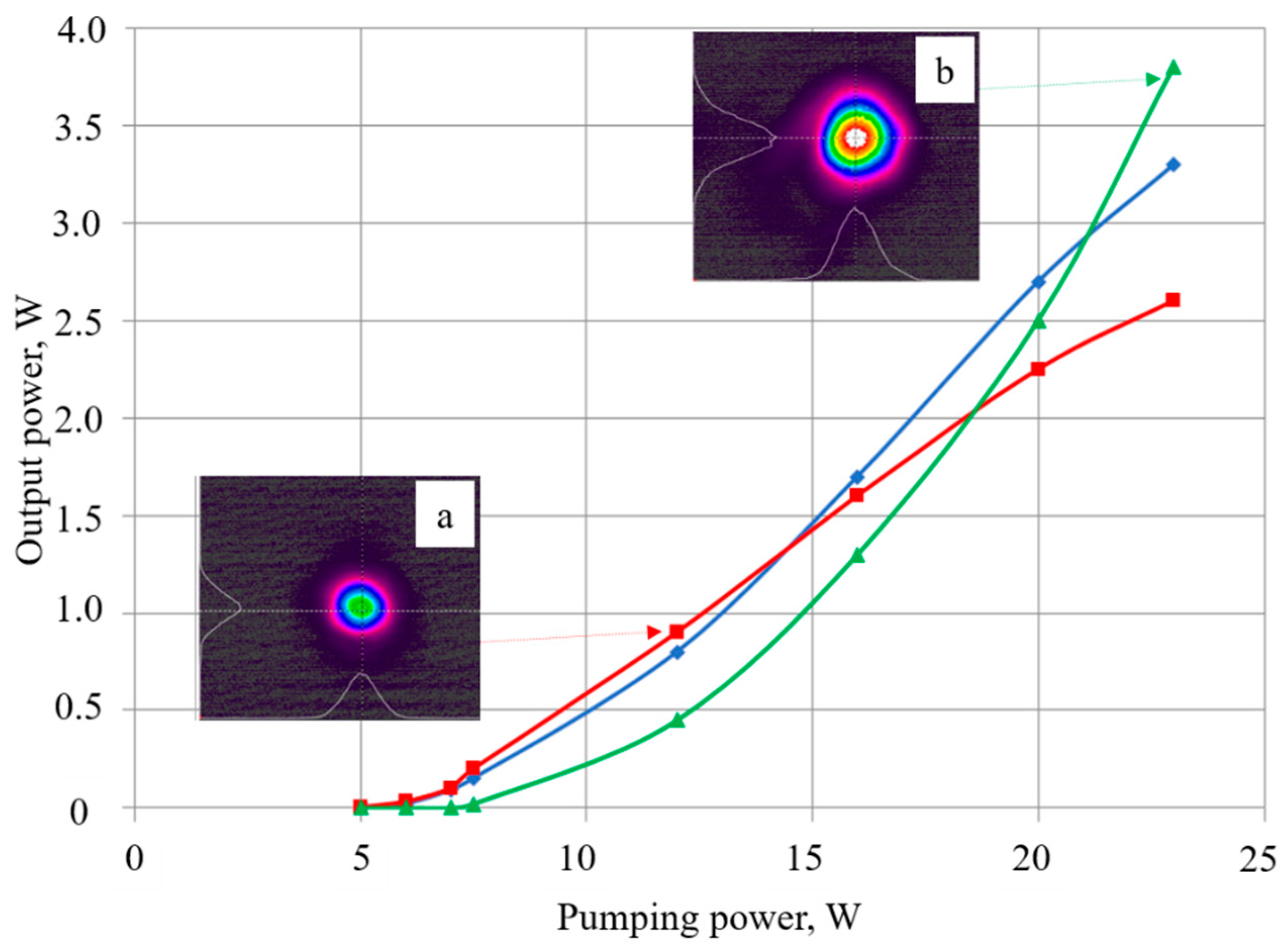
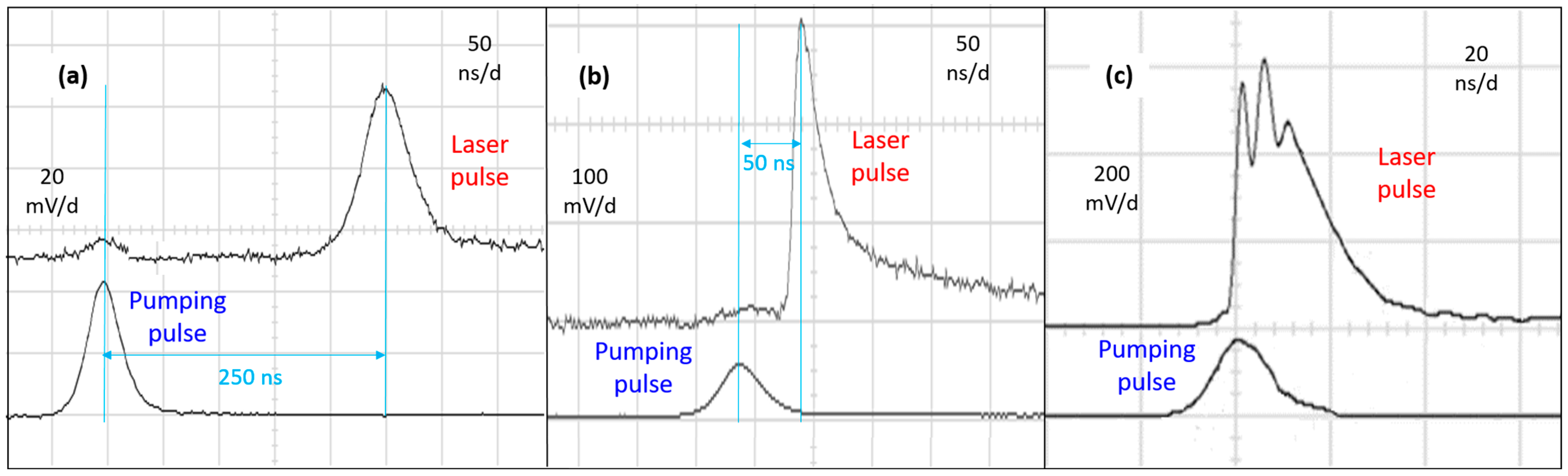
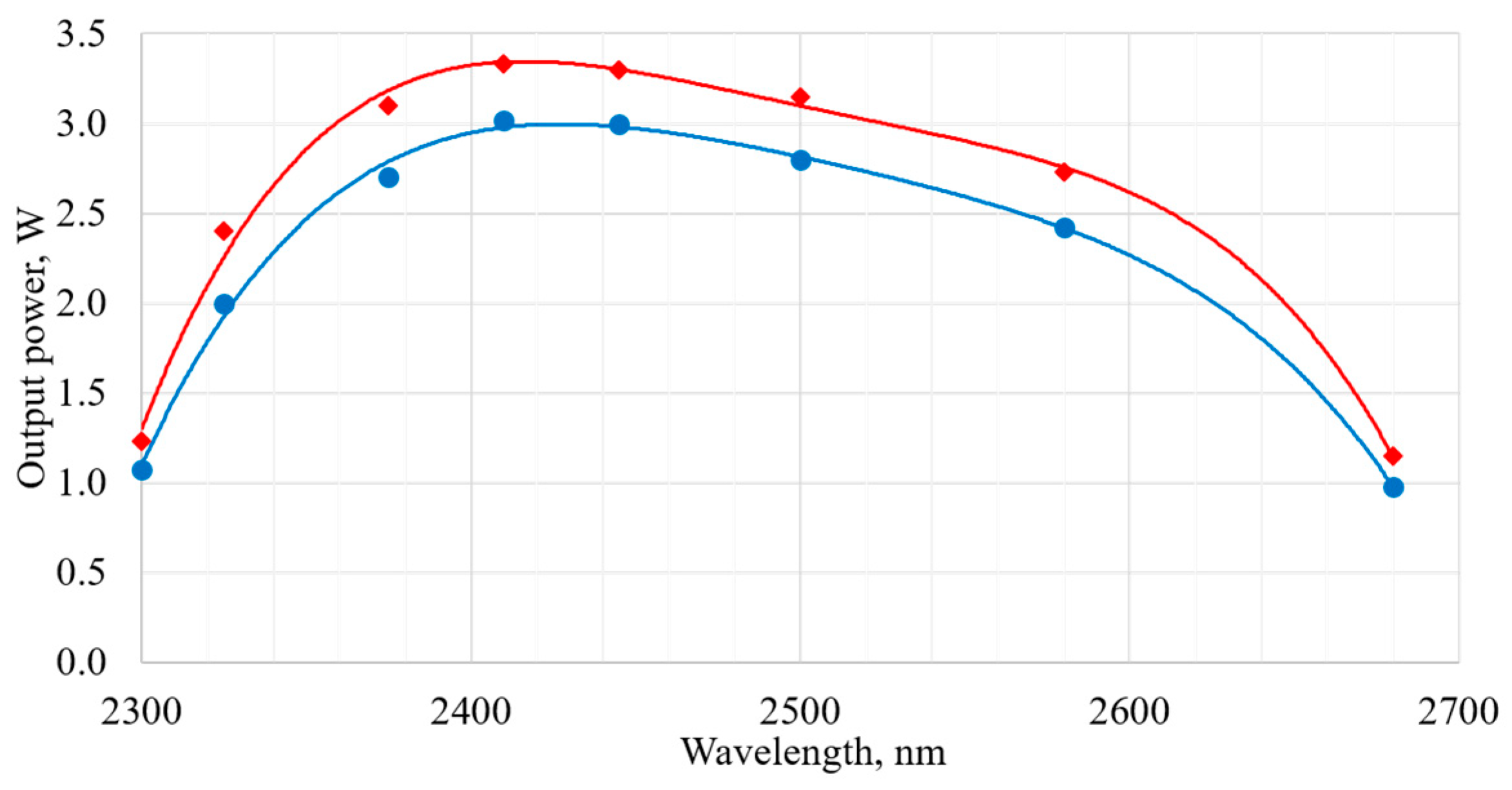
3.3.2. Cr2+:ZnSe Laser Experimental Results

In the first series of experiments, the Cr2+:ZnSe laser was examined without the intracavity AOTF. The repetitively pulsed operation with the highest average output power of 3.8 W at 23 W pumping power and 30 kHz PRR was obtained in the 150 mm long cavity with a 300 mm radius of curvature on rear mirror M1 and the 35% output coupler M3 (Figure 10). The highest output power was achieved with the 16.5 mm long Cr2+:ZnSe element.
The Ophir-Spiricon “PYROCAM IV” beam profiler was used to analyze the Cr2+:ZnSe laser output. The diameter of the output Cr2+:ZnSe laser beam was estimated to be 800–900 µm. The divergence angle and beam quality were analyzed in the focal zone of a lens with a 70 cm focal length using the knife-edge method [44]. The beam quality was M2 ≤ 1.5 at an output power of 3.8 W in the single-transverse-mode regime (Figure 10a).
Waveforms of the Cr2+:ZnSe laser pulses were registered using an in-house-made photodetector based on a PD 36-02 (or 01)-PR(TO18) photodiode manufactured by IBSG Co., Ltd., St. Petersburg, Russia (the spectral response range is 2.3–3.6 μm) in comparison with the pumping pulses of the Ho3+:YAG laser at 2091 nm, which were measured using an in-house-made photodetector based on a HAMAMATSU InGaAs PIN G8422-03 photodiode (the spectral response range is 0.9–2.1 μm). The Cr2+:ZnSe laser operated in the gain-switch mode: the laser pulse was delayed with respect to the pumping pulse, and the delay time decreased with an increase in the pump pulse energy (Figure 11). The laser pulse width decreased from 50–70 ns near the threshold to 20–25 ns far above the threshold.
The output spectrum was measured using an IR Fourier spectrometer FT-801 (Simex, Moscow, Russia). The wavelength of the power maximum and the linewidth were found to depend on both the pump power and the cavity mirrors. The wavelength of the spectral maximum tuned from 2400 nm to 2450 nm with an increase in the average pump power from 8 W to 22 W. The self-tuning of the spectral maximum wavelength can be explained by switching the laser operation from the mirror-reflection maximum at the low pump power to the gain maximum at the higher pump power. The linewidth at half maximum was measured to be ~70 nm at 18 W pump power (Figure 12a) and decreased as the pump power decreased.
The operating wavelength of the Cr2+:ZnSe laser with the intracavity AOTF was tuned through the frequency tuning of the HF driver: from 2300 nm at ~42.6 MHz to 2700 nm at ~36.6 MHz (Figure 12b–e). The discreteness of the wavelength tuning was determined by the discreteness of the AOTF-driver frequency tuning, which was ~1 kHz (corresponding to a discreteness of the laser wavelength tuning of ~0.2 nm). The linewidth of the Cr2+:ZnSe laser with the intracavity AOTF was measured to be strongly ≤0.8 nm (the measurement accuracy was limited by the spectrometer used). The average output power of the electronically tuned Cr2+:ZnSe laser at 23 W pumping power and 30 kHz PRR had a maximum of 3.1–3.3 W at 2410 nm, and decreased to 1.1–1.2 W at 2300 nm and to 0.6–0.8 W at 2700 nm (Figure 13). The beam quality of the tuned Cr2+:ZnSe laser remained high, M2 ≤ 1.5 (the beam quality at 2.3 µm was slightly higher than at 2.5 µm, which can be explained by the decrease in heat generation with the decrease in the pump quantum defect).
The Cr2+:ZnSe laser wave had linear polarization due to the polarization selectivity of cavity mirror M2 and the AOTF. The polarization contrast (measured using a single-crystal silica wedge) was ~70:1 at the highest output power. The output beam of the Cr2+:ZnSe laser was directed to the Cr2+:ZnSe power amplifier by dichroic mirror M4 (Figure 3).

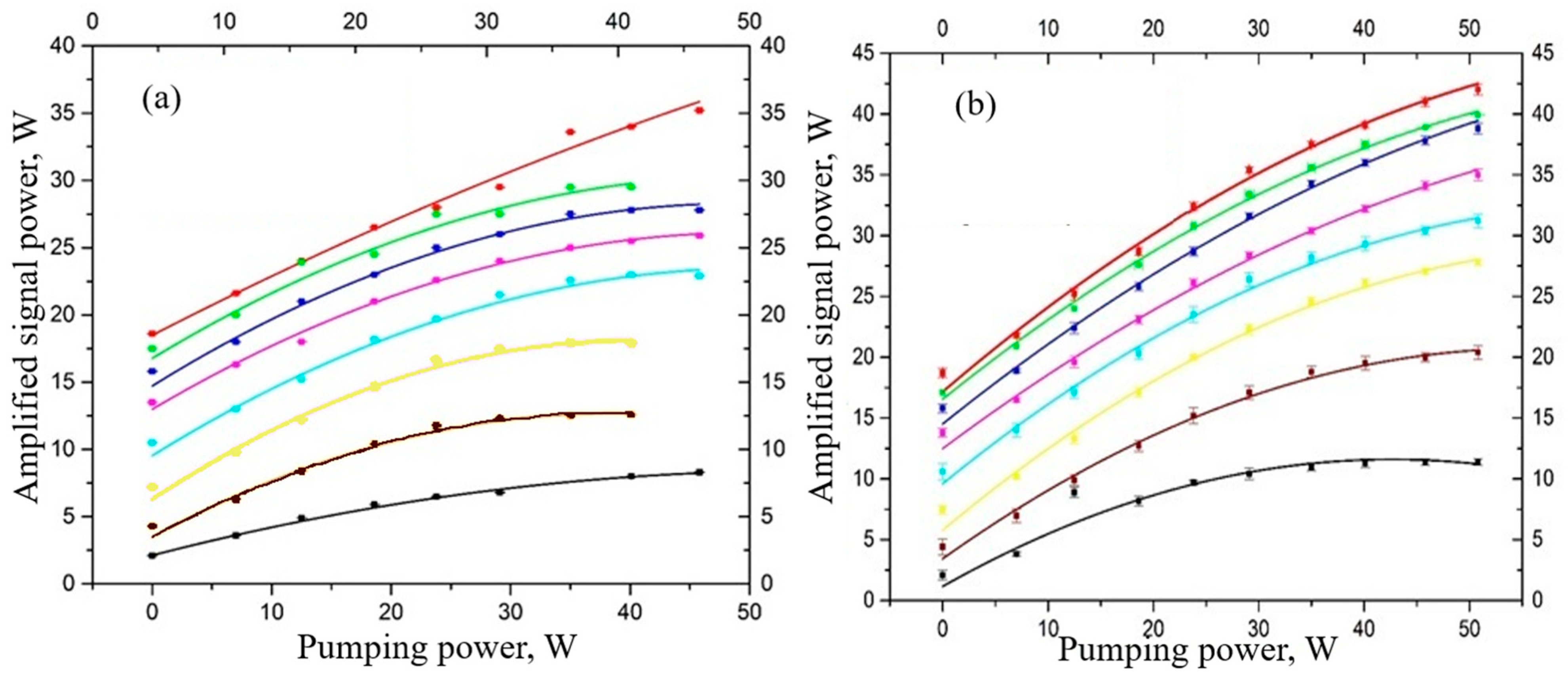
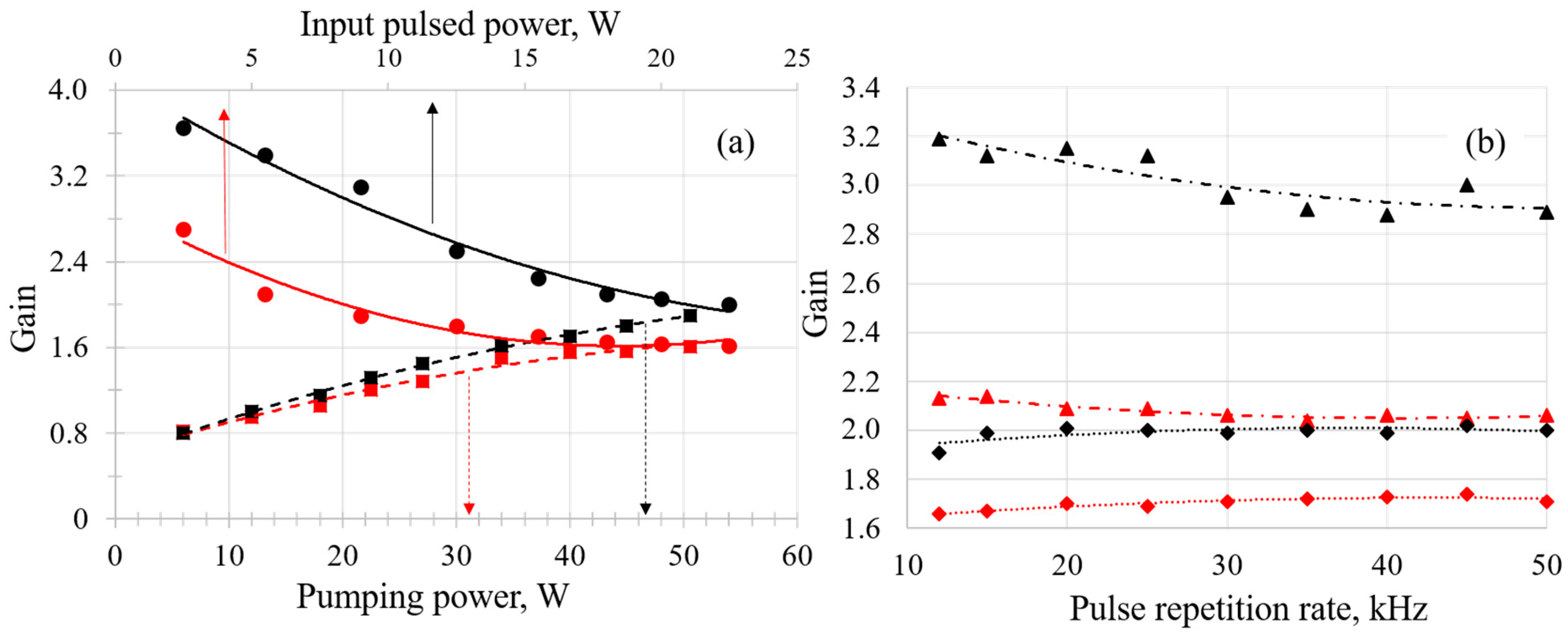
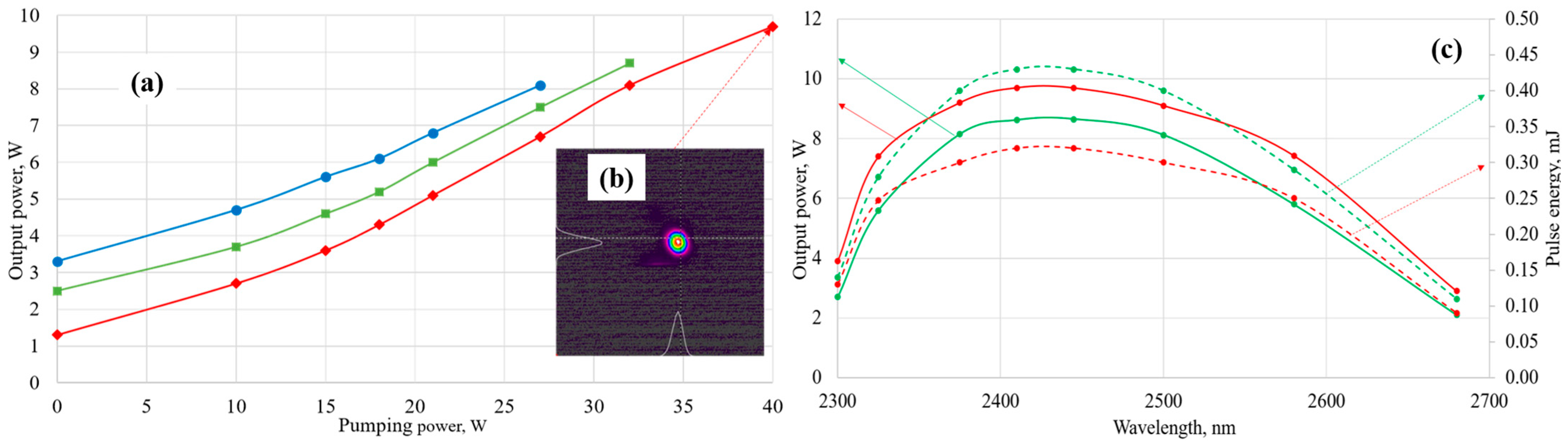
3.4. Cr2+:ZnSe Power Amplifier

Cr2+:ZnSe crystals with length varied from 16 to 32 mm were tested as active elements of the Cr2+:ZnSe amplifiers. The highest output power at 2.3–2.7 µm was achieved with the longest active element of 26–32 mm length.
The diameter of the pump beam at 2091 nm in the Cr2+:ZnSe amplifier was determined by telescope T2 and the thermal lens inside the Ho3+:YAG amplifier. It was chosen to be approximately equal to the diameter of the amplified laser beam in the Cr2+:ZnSe crystal and had a value of 0.9–1.0 mm. To avoid LID in Cr2+:ZnSe, the PRR of the master Ho3+:YAG oscillator was varied only within 20–40 kHz.
The power of the seed (amplified) beam at 2.3–2.7 µm and the pumping beam at 2091 nm was varied by adjusting the polarization beam splitter “P1—λ/2” and the pumping power of the Ho3+:YAG oscillator and amplifier.
A double master oscillator provided automatic time synchronization in the Cr2+:ZnSe amplifying element of pumping pulses of 2091 nm radiation amplified in the Ho:YAG amplifier and the Cr2+:ZnSe laser pulses which came a little later. The 2.3–2.7 µm signal pulse lagged 10–30 ns behind the 2091 nm pump at the Cr2+:ZnSe amplifier. The delay depended on the Cr2+:ZnSe master oscillator pump power. However, this did not affect the amplifier gain, because the lifetime of the Cr2+:ZnSe upper-laser level is much longer.
The maximum average output power and pulse energy of the narrow-line wave at 2.41 µm reached 9.7 W and 0.32 mJ, respectively, at 30 kHz PRR; the total maximum amplifier gain was over a factor of 7 (Figure 14a). The maximum of average power and pulse energy was achieved using the 24 mm long Cr2+:ZnSe amplifier element. The beam quality of the amplified beam was M2 < 2 at the maximum output power (Figure 14b). A slight deterioration in the beam quality of the amplifier output compared to the master-oscillator output can be explained by thermal effects in the long Cr2+:ZnSe amplifier element. The output pulse energy increased, but the average output power decreased with PRR decrease from 30 kHz to 20 kHz (Figure 14c). At stable temperature and environmental conditions in the laboratory, the instability of output pulse peak power and average power was less than 10–15% at 20–30 kHz PRR (the instability of the Ho3+:YAG laser oscillator pulses was less than 5%, and the Cr2+:ZnSe laser oscillator instability was less than 7–10%).

4. Discussion

The power scaling of the Cr2+:ZnSe laser system can be achieved by adding power amplifiers [26,27]. However, several factors limit the pulse energy and the average power of the output beam in the Cr2+:ZnSe lasers: the LID, aberrative thermal lens or self-focusing, and gain saturation.
The rather high saturation fluence of the Cr2+:ZnSe amplifier (62 mJ/cm2 at 2.45 µm) allows for further increases in the output power of the high-PRR nanosecond laser system with strong extraction efficiency. The thermal lens effect and electronic self-focusing can result in decreased beam diameter and the deterioration of beam quality; these effects are more pronounced in longer Cr2+:ZnSe amplifiers. The thermal lens and electronic self-focusing are weaker at the lower beam fluence. For example, a B-integral estimation in the 30 mm amplifying crystal gives the value of approximately 0.34 for the input fluence win = 1 J/cm2 at 2400 nm. Therefore, by increasing the diameter of the signal and pump beams in the amplifier and increasing the PRR, the influence of gain saturation, thermal lens, and self-focusing could be reduced, and the Cr2+:ZnSe crystal LID in the amplifier chain could be avoided. The use of a protective container during the hot isostatic treatment after Cr2+:ZnSe doping helps prevent contamination, resulting in an increase in the LID to 2.0–2.5 J/cm2 at the high PRR.

5. Conclusions

A narrow-line broadly tunable high-PRR laser system based on polycrystalline Cr2+:ZnSe elements, pumped by repetitively pulsed Ho3+:YAG lasers, was developed. Wide-band wavelength electronic tunability was achieved by using the TeO2 AOTF. An average output power of up to 9.7 W at 30 kHz PRR in the single-stage Cr2+:ZnSe power amplifier was reached. The average output power and the pulse energy can be scaled by adding Cr2+:ZnSe amplifier stages.
A compact and powerful Cr2+:ZnSe laser system, tunable within 2.3–2.7 µm, was designed for long-range LIDAR -based environmental monitoring in the transparency window of the Earth’s atmosphere. Several pollutant gases, such as CH4, NH3, CO, and HF, have specific absorption bands in the wavelength range of 2.3–2.7 µm and can be detected using the developed laser source [58,59,60,61]. The small mass-dimensional parameters of the created Cr2+:ZnSe laser system, as well as the electronic control of all its components including wavelength tuning, allow its use for the remote monitoring of pollutant gases near the surface or in the upper atmosphere, both from the Earth’s surface and from an aircraft or low-orbit spacecraft. In addition, the high-average-power repetitively pulsed tunable Cr2+:ZnSe laser system can find applications in other fields: dental hard tissue ablation [62], precision polymer processing [63], the pumping of mid-infrared optical parametric oscillators, and Fe2+-doped solid-state lasers [64,65].

6. Patents

This work resulted in patent EA 041501B1 20221031 from the Eurasian patent office: “IR Laser source based on Cr2+-doped chalcogenide crystals with acousto-optical wavelength tuning”, by O.L. Antipov, I.D. Eranov, and Yu.A. Getmanovskiy [66].

Supplementary Materials

The following supporting information can be downloaded at: https://www.mdpi.com/article/10.3390/photonics11060555/s1, IR Laser Source Based on Cr2+-Doped Chalcogenide Crystals with Acousto-Optical Wavelength Tuning.

Author Contributions

Conceptualization, O.A. and S.B.; methodology, O.A.; software, A.D., Y.G. and V.S.; validation, I.E.; formal analysis, A.D. and Y.G.; investigation, O.A., I.E. and N.Y.; resources, S.B. and O.A.; data curation, Y.G. and N.Y.; writing—original draft preparation, O.A., S.B. and Y.G.; writing—review and editing, O.A. and S.B.; visualization, Y.G.; supervision, O.A. and S.B.; project administration, O.A.; funding acquisition, O.A. All authors have read and agreed to the published version of the manuscript.

Funding

The design and assembly of the laser system were carried out within the framework of the program “Technology of Union State of Russia and Belarus” (project “Technology-SG-3.2.1.2”). The research regarding the optimization of the Cr2+:ZnSe laser system was supported by the Russian Science Foundation (project No. 22-12-20035, https://rscf.ru/en/project/22-12-20035, accessed on 30 April 2024).

Institutional Review Board Statement

Not applicable.

Informed Consent Statement

Not applicable.

Data Availability Statement

Data are contained within the article and Supplementary Materials.

Conflicts of Interest

The authors declare no conflicts of interest. The funders had no role in the design of the study; in the collection, analyses, or interpretation of data; in the writing of the manuscript, or in the decision to publish the results.

References

  1. Cha, S.; Chan, K.P.; Killinger, D.K. Tunable 2.1-µm Ho lidar for simultaneous range-resolved measurements of atmospheric water vapor and aerosol backscatter profiles. Appl. Opt. 1991, 30, 3938–3943. [Google Scholar] [CrossRef] [PubMed]
  2. Sorokin, E.; Sorokina, I.T.; Fischer, C.; Sigrist, M.W. Widely Tunable Cr2+:ZnSe Laser Source for Trace Gas Sensing. In Proceedings of the Advanced Solid State Photonics, Vienna, Austria, 6–9 February 2005. MD4. [Google Scholar]
  3. Hodgkinson, J.; Tatam, R. Optical gas sensing: A review. Meas. Sci. Technol. 2013, 24, 012004. [Google Scholar] [CrossRef]
  4. Hossain, M.; Nakamura, Y.; Yamada, Y.; Kimura, K.; Matsumoto, N.; Matsumoto, K. Effects of Er, Cr:YSGG laser irradiation in human enamel and dentin: Ablation and morphological studies. J. Clin. Laser Med. Surg. 1999, 17, 155–159. [Google Scholar] [CrossRef] [PubMed]
  5. Vogel, A.; Venugopalan, V. Mechanisms of Pulsed Laser Ablation of Biological Tissues. Chem. Rev. 2003, 103, 577–644. [Google Scholar] [CrossRef] [PubMed]
  6. Antipov, O.L.; Zakharov, N.G.; Fedorov, M.; Shakhova, N.M.; Prodanets, N.N.; Snopova, L.B.; Sharkov, V.V.; Sroka, R. Cutting effects induced by 2 μm laser radiation of cw Tm:YLF and cw and Q-switched Ho:YAG lasers on ex-vivo tissue. Med. Laser Appl. 2011, 26, 67–75. [Google Scholar] [CrossRef]
  7. Tarabrin, M.K.; Ustinov, D.V.; Tomilov, S.M.; Lazarev, V.A.; Karasik, V.E.; Kozlovsky, V.I.; Korostelin, Y.V. High-efficiency continuous-wave single-moderoom-temperature operation of Cr:CdSe single-crystal laser with output power of 2.3 W. Opt. Express 2019, 27, 12090–12099. [Google Scholar] [CrossRef]
  8. Antipov, O.L.; Streltsova, O.S.; Pochtin, D.P.; Eranov, I.D.; Grebenkin, E.V. Lasertripsy for the controlled coarse fragmentation of urinary tract stones. J. Urol. Nephrol. Stud. 2018, 1, 41–43. [Google Scholar] [CrossRef]
  9. Vodopyanov, K.L.; Ganikhanov, F.; Maffetone, J.P.; Zwieback, I.; Ruderman, W. ZnGeP2 optical parametric oscillator with 3.8–12.4-µm tenability. Opt. Lett. 2000, 25, 841–843. [Google Scholar] [CrossRef]
  10. Vodopyanov, K.L. Laser-Based Mid-Infrared Sources and Applications; John Wiley & Sons Inc.: Hoboken, NJ, USA, 2020; p. 247. [Google Scholar]
  11. Fedorov, V.; Mirov, S.; Gallian, A.; Badikov, D.; Frolov, M.; Korostelin, Y.; Kozlovsky, V.; Landman, A.; Podmar’kov, Y.; Akimov, V.; et al. 3.77–5.05-μm tunable solid-state lasers based on Fe2+-doped ZnSe crystals operating at low and room temperatures. IEEE J. Quantum Electron. 2006, 42, 907–917. [Google Scholar] [CrossRef]
  12. DeLoach, L.D.; Page, R.H.; Wilke, G.D.; Payne, S.A.; Krupke, W.F. Transition metal-doped zinc chalcogenides: Spectroscopy and laser demonstration of a new class of gain media. IEEE J. Quantum Electron. 1996, 32, 885–895. [Google Scholar] [CrossRef]
  13. Page, R.H.; Schaffers, K.I.; DeLoach, L.D.; Wilke, G.D.; Patel, F.D.; Tassano, J.B.; Payne, S.A.; Krupke, W.F.; Chen, K.T.; Burger, A. Cr2+-doped zinc chalcogenides as efficient, widely tunable mid-infrared lasers. IEEE J. Quantum Electron. 1997, 33, 609. [Google Scholar] [CrossRef]
  14. Carrig, T.J. Transition-Metal-Doped Chalcogenide Lasers. J. Electron. Mater. 2002, 31, 759–769. [Google Scholar] [CrossRef]
  15. Gavrishchuk, E.M. Polycrystalline Zinc Selenide for IR Optical Applications. Inorg. Mater. 2003, 39, 883–899. [Google Scholar] [CrossRef]
  16. Levchenko, V.I.; Yakimovich, V.N.; Postnova, L.I.; Konstantinov, V.I.; Mikhailov, V.P.; Kuleshov, N.V. Preparation and properties of bulk ZnSe:Cr single crystals. J. Cryst. Growth 1999, 198–199, 980–983. [Google Scholar] [CrossRef]
  17. Mirov, S.B.; Fedorov, V.V.; Graham, K.; Moskalev, I.S.; Badikov, V.V.; Panyutin, V. Erbium fiber laser-pumped continuous-wave microchip Cr2+:ZnS and Cr2+:ZnSe lasers. Opt. Lett. 2002, 27, 909–911. [Google Scholar] [CrossRef] [PubMed]
  18. Mirov, S.B.; Fedorov, V.V.; Martyshkin, D.; Moskalev, I.S.; Mirov, M.; Vasilyev, S. Progress in Mid-IR Lasers Based on Cr and Fe Doped II–VI Chalcogenides. IEEE J. Sel. Top. Quantum Electron. 2015, 21, 1601719. [Google Scholar] [CrossRef]
  19. Mirov, S.; Moskalev, I.; Vasilyev, S.; Smolski, V.; Fedorov, V.; Martyshkin, D.; Peppers, J.; Mirov, M.; Dergachev, A.; Gapontsev, V. Frontiers of mid-IR lasers based on transition metal doped chalcogenides. IEEE J. Sel. Top. Quantum Electron. 2018, 24, 1–29. [Google Scholar] [CrossRef]
  20. Sennaroglu, A.; Morova, Y. Divalent (Cr2+), trivalent (Cr3+), and tetravalent (Cr4+) chromium ion-doped tunable solid-state lasers operating in the near and mid-infrared spectral regions. Appl. Phys. B 2022, 128, 9. [Google Scholar] [CrossRef]
  21. Berry, P.A.; Schepler, K.L. High-power, widely tunable Cr2+: ZnSe laser. In Proceedings of the Conference on Lasers and Electro-Optics 2010, CLEO’2010 (Optica Publishing Group, 2010), San Jose, CA, USA, 16–21 May 2010. paper CMDD5. [Google Scholar]
  22. Carrig, T.J.; Wagner, G.J.; Alford, W.J.; Zakel, A. Chromium-doped chalcogenide lasers. In Proceedings of the SPIE—The International Society for Optical Engineering 5460, Bellingham, WA, USA, 1 September 2004; pp. 74–82. [Google Scholar]
  23. Zakel, A.; Wagner, G.J.; Sullivan, A.C.; Wenzel, J.F.; Alford, W.J.; Carrig, T.J. High-brightness, rapidly tunable Cr:ZnSe lasers. In Proceedings of the Advanced Solid State Photonics 2005, Vienna, Austria, 6–9 February 2005. MD2. [Google Scholar]
  24. Meng, P.; Yao, B.; Li, G.; Ju, Y.; Wang, Y. Tunable, narrow linewidth, linearly polarized and gain-switched Cr2+:ZnSe laser. Laser Phys. 2011, 21, 352–355. [Google Scholar] [CrossRef]
  25. Yumoto, M.; Saito, N.; Takagi, U.; Wada, S. Electronically tuned Cr:ZnSe laser pumped with Q-switched Tm:YAG laser. Opt. Express 2015, 23, 25009–25016. [Google Scholar] [CrossRef]
  26. Yumoto, M.; Saito, N.; Wada, S. 50 mJ/pulse, electronically tuned Cr:ZnSe master oscillator power amplifier. Opt. Express 2017, 25, 32948–32956. [Google Scholar] [CrossRef]
  27. Berry, P.A.; Schepler, K.L. High-power, widely-tunable Cr2+:ZnSe master oscillator power amplifier systems. Opt. Express 2010, 18, 15062–15072. [Google Scholar] [CrossRef]
  28. Moskalev, I.; Fedorov, V.; Mirov, S. Tunable, single-frequency, and multi-watt continuous-wave Cr2+:ZnSe lasers. Opt. Express 2008, 16, 4145–4153. [Google Scholar] [CrossRef]
  29. Aikawa, S.; Yumoto, M.; Saito, T.; Wada, S. Mid-infrared tunable pulsed laser based on Cr2+-doped II–VI chalcogenide. J. Cryst. Growth 2021, 575, 126341. [Google Scholar] [CrossRef]
  30. Sorokin, E.; Sorokina, I.T. Tunable diode-pumped continuous-wave Cr2+:ZnSe laser. Appl. Phys. Lett. 2002, 80, 3289–3291. [Google Scholar]
  31. Wagner, G.J.; Carrig, T.J.; Page, R.H.; Schaffers, K.I.; Ndap, J.; Ma, X.; Burger, A. Continuous-wave broadly tunable Cr2+:ZnSe laser. Opt. Lett. 1999, 24, 19–21. [Google Scholar] [CrossRef]
  32. Demirbas, U.; Sennaroglu, A. Intracavity-pumped Cr2+:ZnSe laser with ultrabroad tuning range between 1880 and 3100 nm. Opt. Lett. 2006, 31, 2293–2295. [Google Scholar] [CrossRef] [PubMed]
  33. Antipov, O.L. High-Efficiency Repetitively-Pulsed 2.3–3.2 μm Lasers based on Cr2+-doped Single-Crystalline or Polycrystalline Chalcogenides with Low-Quantum-Defect Pumping. In Proceedings of the 2020 International Conference Laser Optics (ICLO), St. Petersburg, Russia, 2–6 November 2020; p. 1. [Google Scholar]
  34. Antipov, O. Wavelength tuned mid-IR lasers based on single-crystalline or polycrystalline Cr2+-doped ZnSe with 1.9−2.1 μm pumping. In Proceedings of the 2022 International Conference Laser Optics (ICLO), St. Petersburg, Russia, 20–24 June 2022; p. 1. [Google Scholar]
  35. Turner, E.J.; McDaniel, S.A.; Tabiryan, N.; Cook, G. Rapidly tunable HIP treated Cr:ZnSe narrow-linewidth laser. Opt. Express 2019, 27, 12282–12288. [Google Scholar] [CrossRef] [PubMed]
  36. Cankaya, H.; Cizmeciyan, M.N.; Beyatlı, E.; Gorgulu, A.T.; Kurt, A.; Sennaroglu, A. Injection-seeded, gain-switched tunable Cr: ZnSe laser. Opt. Lett. 2012, 37, 136–138. [Google Scholar] [CrossRef]
  37. Chang, I.C. Acousto-optic tunable filters. Opt. Eng. 1981, 20, 824–829. [Google Scholar] [CrossRef]
  38. Hobbs, D.S.; MacLeod, B.D.; Sabatino, E.; Mirov, S.B.; Martyshkin, D.V. Laser Damage Resistant Anti-Reflection Microstructures for Mid-Infrared Metal-Ion Doped ZnSe Gain Media. SPIE Proc. 2012, 8530, 164–178. [Google Scholar]
  39. McDaniel, S.; Hobbs, D.; MacLeod, B.; Sabatino, E.; Berry, P.; Schepler, K.; Mitchell, W.; Cook, G. Cr:ZnSe laser incorporating anti-reflection microstructures exhibiting low-loss, damage-resistant lasing at near quantum limit efficiency. Opt. Mater. Express 2014, 4, 2225–2232. [Google Scholar] [CrossRef]
  40. Yudin, N.; Antipov, O.; Balabanov, S.; Eranov, I.; Getmanovskiy, Y.; Slyunko, E. Effects of the Processing Technology of CVD-ZnSe, Cr2+:ZnSe, and Fe2+:ZnSe Polycrystalline Optical Elements on the Damage Threshold Induced by a Repetitively Pulsed Laser at 2.1 µm. Ceramics 2022, 5, 459–471. [Google Scholar] [CrossRef]
  41. Gavrishchuk, E.M.; Kurashkin, S.V.; Savin, D.V.; Timofeev, O.V. Effect of Magnetorheological Polishing on Laser-Induced Damage in ZnSe and ZnSe:Cr Polycrystals. Appl. Phys. B 2023, 129, 1. [Google Scholar] [CrossRef]
  42. Rodin, S.A.; Gavrishchuk, E.M.; Ikonnikov, V.B.; Savin, D.V. Effect of Annealing Atmosphere on Chromium Diffusion in CVD ZnSe. Inorg. Mater. 2018, 54, 21–25. [Google Scholar] [CrossRef]
  43. Antipov, O.; Kositsyn, R.; Eranov, I. 36W Q-switched Ho3+:YAG laser at 2097 nm pumped by a Tm fiber laser: Evaluation of different Ho3+ doping concentrations. Laser Phys. Lett. 2017, 14, 015002. [Google Scholar] [CrossRef]
  44. ISO 11146-1:2021; Lasers and Laser-Related Equipment—Test Methods for Laser Beam Widths, Divergence Angles and Beam Propagation Ratios—Part 1: Stigmatic and Simple Astigmatic Beams. ISO: Geneva, Switzerland, 2021.
  45. Frantz, L.M.; Nodvik, J.S. Theory of pulse propagation in a laser amplifier. J. Appl. Phys. 1963, 34, 2346–2349. [Google Scholar] [CrossRef]
  46. Anashkina, E.; Antipov, O. Electronic (population) lensing versus thermal lensing in Yb: YAG and Nd: YAG laser rods and disks. J. Opt. Soc. Am. B 2010, 27, 363–369. [Google Scholar] [CrossRef]
  47. Elliott, C.J. Gain saturation and self-focusing considerations in the design of optical amplifiers. Appl. Phys. Lett. 1974, 24, 91–93. [Google Scholar] [CrossRef]
  48. Koechner, W. Solid-State Laser Engineering; Springer: Berlin/Heidelberg, Germany, 1999; Chapter 7; p. 468. [Google Scholar]
  49. Antipov, O.L.; Dobrynin, A.A.; Getmanovskiy, Y.A.; Sharkov, V.V.; Shestakova, I.A.; Balabanov, S.S.; Larin, S.V. CW and Q-switched operations of a Tm3+:YAP laser at 1892–1994 nm In-band fiber-laser pumped at 1670 nm. Laser Phys. 2022, 32, 085802–085808. [Google Scholar] [CrossRef]
  50. William, M.; Bruno, J.; David, R. CRC Handbook of Chemistry and Physics: A Ready-Reference Book of Chemicaland Physical Data; CRC Press: Boca Raton, FL, USA, 2014; p. 2704. [Google Scholar]
  51. Sorokina, I.T. Cr2+-doped II–VI materials for lasers and nonlinear optics. Opt. Mater. 2004, 26, 395. [Google Scholar] [CrossRef]
  52. Marple, D.T.F. Refractive index of ZnSe, ZnTe, and CdTe. J. Appl. Phys. 1964, 35, 539–542. [Google Scholar] [CrossRef]
  53. Li, H.H. Refractive index of alkaline earth halides and its wavelength and temperature derivatives. J. Phys. Chem. 1980, 9, 161–290. [Google Scholar] [CrossRef]
  54. Pollock, D.B. Thermal Expansion Values for Installation of an lrtran-6 Window. Appl. Opt. 1969, 8, 837–838. [Google Scholar] [CrossRef]
  55. Khatta, S.; Kaur, V.; Tripathi, S.K.; Prakash, S. The first principles study of elastic and thermodynamic properties of ZnSe. AIP Conf. Proc. 2018, 1953, 130016. [Google Scholar]
  56. Acousto-Optic Database. Available online: www.acousto-optics.phys.msu.ru (accessed on 29 April 2024).
  57. Available online: www.rezonator.orion-project.org (accessed on 29 April 2024).
  58. Gordon, I.E.; Rothman, L.S.; Hargreaves, R.J.; Hashemi, R.; Karlovets, E.V.; Skinner, F.M.; Conway, E.K.; Hill, C.; Kochanov, R.V.; Tan, Y.; et al. The HITRAN2020 molecular spectroscopic database. J. Quant. Spectrosc. Radiat. Transf. 2022, 277, 107949. Available online: www.hitran.org (accessed on 29 April 2024).
  59. Richter, D.; Fried, A.; Wert, B.P.; Waleg, J.G.; Tittel, F.K. Development of a tunable mid-IR difference frequency laser source for highly sensitive airborne trace gas detection. Appl. Phys. B 2002, 75, 281. [Google Scholar] [CrossRef]
  60. Tittel, F.K.; Richter, D.; Fried, A. Mid-infrared laser applications in spectroscopy. In Solid-State Mid-Infrared Laser Sources, Topics in Applied Physics; Sorokina, I.T., Vodopyanov, K.L., Eds.; Springer: Berlin/Heidelberg, Germany, 2003; Volume 89. [Google Scholar]
  61. Bobrovnikov, S.M.; Matvienko, G.G.; Romanovsky, O.A.; Serikov, I.B.; Sukhanov, A.Y. Lidar Spectroscopic Gas Analysis of the Atmosphere; IOA SB RAS: Tomsk, Russia, 2014; p. 510. [Google Scholar]
  62. Santos, C.R.; Tonetto, M.R.; Presoto, C.D.; Bandéca, M.C.; Oliveira, O.B.; Calabrez-Filho, S.; Andrade, M.F. Application of Er:YAG and Er,Cr:YSGG Lasers in Cavity Preparation for Dental Tissues: A Literature Review. World J. Dent. 2012, 3, 340–343. [Google Scholar]
  63. Duval, S. Laser Processing of Polymer in the Mid-Infrared—Why? 2021. Available online: www.femtum.com (accessed on 19 May 2024).
  64. Yumoto, M.; Saito, N.; Wada, S. Energy ZnGeP2 Optical Parametric Oscillator Pumped with Rapidly Tunable Cr:ZnSe Laser. In Nonlinear Optics Technical Digest; Paper NW4A.19; Optica Publishing Group: Washington, DC, USA, 2013. [Google Scholar]
  65. Kozlovsky, V.I.; Korostelin, Y.V.; Podmar’kov, Y.P.; Skasyrsky, Y.K.; Frolov, M.P. Middle infrared Fe2+:ZnS, Fe2+:ZnSe and Cr2+:CdSe lasers: New results. J. Phys. Conf. Ser. 2016, 740, 012006. [Google Scholar] [CrossRef]
  66. Antipov, O.L.; Eranov, I.D.; Getmanovskiy, Y.A. IR Laser Source Based on Cr2+-Doped Chalcogenide Crystals with Acousto-Optical Wavelength Tuning. EA 041501B1, 31 October 2022. [Google Scholar]
Figure 1. Photographs of the active elements made from polycrystalline Cr2+:ZnSe: side view with measured length indication (a), and the front side with antireflection coating (b).
Photonics 11 00555 g001
Figure 2. Absorption (blue) and emission (red) cross sections of the Cr2+:ZnSe crystal. The dashed lines of different colors indicate the calculated effective gain cross section, G, at zero passive losses (γ = 0) and for the different value of the inversion fraction β: 0.03 (gray), 0.1 (green), and 0.2 (brown). The blue pointer indicates the wavelength of the pumping Ho3+:YAG laser, and the gray-filled area is the operational wavelength span (tuning range) of the tunable Cr2+:ZnSe laser.
Photonics 11 00555 g002
Figure 3. Schematics of the Cr2+:ZnSe laser system: M1–M5 are the mirrors, P1–P2 are the polarizers, T1–T3 are the Galilean telescopes, FI is the Faraday isolator, and AOTF is the acousto-optical tunable filter; Cr2+:ZnSe and Ho3+:YAG are the laser and amplifier active elements. The blue pointer and the blue dot on the beams indicate the polarization direction. The red, blue, yellow, and violet lines and arrows indicate the Cr2+:ZnSe laser beam, the Ho3+:YAG laser beams, the Tm fiber laser beam, and the AOTF undeflected wave, respectively. The dot in the circle and the arrow perpendicular to the beam line show the directions of wave polarization. The white-green grating indicates the acousto-optical wave inside the AOTF.
Photonics 11 00555 g003
Figure 4. Operating wavelength measured using an OSA203 spectrum analyzer (Thorlabs, Newton, NJ, USA) (a) and beam profile (b) of the Ho3+:YAG laser.
Photonics 11 00555 g004
Figure 5. The amplifier power of the repetitively pulsed beam at 2091 nm vs. the CW power of the fiber laser beam at 1908 nm, at 20 kHz, and an input power of 2.2 W (black), 3.1 W (brown), 6 W (yellow), 10.1 W (white-blue), 12.9 W (violet), 15.3 W (dark blue), 17.2 W (green), and 18.1 (red) for the Ho3+:YAG rod with a length of 50 mm (a) or 65 mm (b).
Photonics 11 00555 g005
Figure 6. The Ho3+:YAG-amplifier gain vs. the CW pumping power (the dashed lines) at the 21.6 W output power or the input power of the amplified beam (the solid lines) at the 50.6 W pumping power 20 kHz PRR (a). The gain vs. the PRR at the input signal power of 9.6 W (the doted lines) or 21.6 W (the dashed-dotted lines) and the 50.6 W pumping power (b). The gains of the 50 mm long rod (red) or the 65 mm long rod (black) are shown on both (a,b) parts of the figure.
Photonics 11 00555 g006
Figure 7. The beam profile at the output of the Ho3+:YAG amplifier with the 65 mm rod at the output power of 30 W (a) or 43 W (b).
Photonics 11 00555 g007
Figure 8. Numerically calculated focal length of the steady-state (brown) and transient (blue) thermal lenses in the Cr2+:ZnSe crystal vs. the average input pump power at 2091 nm (a), and the gain cross section in the Cr2+:ZnSe crystal for an input pump power of 3 W (gray), 10 W (green), and 30 W (red) (b). The calculation was performed for the Cr2+:ZnSe crystal parameters presented in Table 1.
Photonics 11 00555 g008
Figure 9. The calculated radius of the fundamental mode in the Cr2+:ZnSe laser cavity with the active rod (brown) and the AOTF (green) for an input pumping power of 3 W (blue), 5 W (brown), and 7 W (gray) (a); the cavity mode radius at the right end of the active rod vs. the total cavity length for an input pumping power of 10 W (green), 9 W (yellow), 7 W (gray), 5 W (orange), and 3 W (blue) (b). The pumping beam radius at the active rod is 450 µm (the red lines in both figures). Rear mirror M1 with a 300 mm radius of curvature was assumed for the calculations.
Photonics 11 00555 g009
Figure 10. The average output power of the Cr2+:ZnSe laser with a 16.5 mm long active element vs. the pumping power at PRR of 15 kHz (red), 25 kHz (blue), or 30 kHz (green) in the 150 mm long cavity with output coupler M3 with a transmission of 50% (red and blue) or 65% (green). The inserts show the PYROCAM images of the Cr2+:ZnSe laser output beam at an average power of 0.9 W (a) or 3.8 W (b).
Photonics 11 00555 g010
Figure 11. Waveforms of the Cr2+:ZnSe laser pulses (upper curves) and the input pumping pulses (lower curves) for different input pumping powers, Pin: near the oscillation threshold at Pin = 7 W (a), above the threshold at Pin = 15 W (b), and far above the threshold at Pin = 23 W (c). The PRR was 20 kHz.
Photonics 11 00555 g011
Figure 12. The output spectrum of the Cr2+:ZnSe laser in the cavity with a 50% output coupler without AOTF at 18 W pump power (a), and with AOTF at tuning frequencies of 42.6 MHz (b), 40.7 MHz (c), 38.1 MHz (d), and 36.8 MHz (e).
Photonics 11 00555 g012
Figure 13. Output power of the narrow-linewidth wavelength-tuned Cr2+:ZnSe laser with an active element length of 16.5 mm (blue) or 20 mm (red) at 23 W pump power and 30 kHz PRR vs. the operating wavelength.
Photonics 11 00555 g013
Figure 14. The average output power of the Cr2+:ZnSe amplifier at 2410 nm and 30 kHz PRR vs. the pumping power at 2091 nm at different average input power: 1.3 W (red), 2.5 W (green), and 3.3 W (blue) (a). The 2.4 µm output beam image at 9.7 W average power in the insert (b). The average power (solid lines) and pulse-energy (dashed lines) spectra of the narrow-line output for a PRR of 20 kHz (green lines) or 30 kHz (red lines) (c). The Cr2+:ZnSe element length was 28 mm.
Photonics 11 00555 g014
Table 1. Key parameters of the Cr2+:ZnSe crystal, laser cavity, and the pump beam used for the numerical calculations, and the calculated focal length of a thermal lens in the laser element.
ParameterValue
Density of the doping Cr2+ ions, cm−35 × 1018
Density of the ZnSe crystal ρ, g/cm35.27 [50]
Specific heat capacity of the ZnSe crystal, Cp, J/(g K)0.34 [50]
Thermal conductivity of the Cr2+:ZnSe crystal, KT, W/(cm K)0.18 [14,19,51]
Refractive index of the Cr2+:ZnSe crystal (at 2400 nm), n2.43 [52]
Thermo-optic coefficient of the ZnSe crystal, (∂n/∂T),
K−1
61 × 10−5 [19,53]
Thermal expansion coefficient of the ZnSe crystal, βT, K−17.3 × 10⁻⁶ [54]
Absorption cross section of the Cr2+:ZnSe crystal (at 2091 nm), σabs, cm214 × 10−20 [18]
Emission cross section of the Cr2+:ZnSe crystal (at 2450 nm), σem, cm2
Poisson’s ratio of the ZnSe crystal, ν
13 × 10−19 [18]
0.28 [55]
Length of the Cr2+:ZnSe element L, mm16.5
Refractive index of TeO2 for the ordinary and extraordinary waves, noTeO and neTeO (at 2400 nm)2.17 and 2.3 [56]
Length of the AOTF element, mm25
Curvature of the M1 rear mirror, mm300
Pump beam radius ap (at e−2 intensity), µm450
Estimated focal length of the steady-state thermal lens in the Cr2+:ZnSe crystal (at the average input pump power, Pin), fT, mm
Electronic nonlinear refractive index, n2, cm2/W
28 (at 10 W)
14 (at 20 W)
1.2 × 10⁻¹⁴ [11,20]
Disclaimer/Publisher’s Note: The statements, opinions and data contained in all publications are solely those of the individual author(s) and contributor(s) and not of MDPI and/or the editor(s). MDPI and/or the editor(s) disclaim responsibility for any injury to people or property resulting from any ideas, methods, instructions or products referred to in the content.

