Next Article in Journal
Photodynamic Therapy under Diagnostic Control of Wounds with Antibiotic-Resistant Microflora
Next Article in Special Issue
Laser Machining at High ∼PW/cm2 Intensity and High Throughput
Previous Article in Journal
Refraction-Based Laser Scanning Microcantilever Array System
Previous Article in Special Issue
Advances in Lensless Fluorescence Microscopy Design
 
 
Correction published on 21 October 2024, see Photonics 2024, 11(10), 992.
Article

Monolithically Integrated Michelson Interferometer Using an InGaAs/InAlAs Quantum Cascade Laser at λ = 4 µm

1
Independent Researcher, Chemin du Château 5, 2068 Hauterive, Switzerland
2
Independent Researcher, Rue des Peupliers 6, 2014 Bôle, Switzerland
3
Google LLC, 1250 Reliance Way, Fremont, CA 94539, USA
*
Author to whom correspondence should be addressed.
Photonics 2024, 11(7), 593; https://doi.org/10.3390/photonics11070593
Submission received: 27 May 2024 / Revised: 14 June 2024 / Accepted: 19 June 2024 / Published: 26 June 2024 / Corrected: 21 October 2024
(This article belongs to the Special Issue Advanced Photonic Sensing and Measurement II)

Abstract

:
In the present article, we propose a monolithically integrated Michelson interferometer using a λ = 4 µm InGaAs/InAlAs quantum cascade (QC) laser as the light source. By using simple fringe detection and a four-point interpolation on each fringe, we will be able to detect minimal object displacements of 500 nm—corresponding to 25% of half the laser emission wavelength. Such an interferometric photonic integrated circuit has interesting applications for precision computerized numerical controlled machines. Since the industrial standard of such machines currently consists of glass-based linear encoders with a resolution of 5 µm, our interferometer-based system will enable an improvement of at least one order of magnitude.

Graphical Abstract

1. Introduction

The first modern interferometer experiment was carried out by A A Michelson in the year 1881 [1]. However, since the quite long and relatively thin arms of this optical apparatus tended to vibrate even under very careful handling, A A Michelson fabricated and characterized an improved version of his interferometer in 1887. The corresponding measurements were carried out together with E W Morley—using (in principle) the same experimental configuration as six years earlier [2]. However, in this second, much more stable experiment, the entire optical instrumentation was literally “floating” on a big trough filled with liquid mercury. With this important work, the two researchers invented, built, and characterized the optical interferometer that bears their names until today. The goal of these experiments was to precisely measure the velocity of the Earth relative to the “luminiferous ether”—the hypothetical medium that was supposed to “carry” the electromagnetic waves. However, the “Michelson-Morley experiment” (as it is referred to today) resulted in a relative velocity of zero (vrel = 0); therefore, it unambiguously proved the non-existence of the luminiferous ether. Electromagnetic radiation can, therefore, also propagate in a vacuum, for example, in space. The experimental realization of the seminal work of A A Michelson and E W Morley is shown in Figure 1 below. Just about two decades later, the surprising outcome of this research effort contributed to A Einstein’s special theory of relativity, within which he postulated that the speed of light is a “universal natural constant”, meaning that it is independent from the observer’s relative velocity [3,4].
Much more recently, Michelson interferometers have made their way into industrial applications such as high-precision positioning [5] or distance measurements [6]. Successful approaches include the glass-based device of Jestel et al. [7] and the silicon-based interferometer of Ulbers [8]. In 2006, fiber optic Michelson interferometers were demonstrated as well [9,10]. However, although most of these devices were already using an integration of several optical components on a single substrate, they did not include an integrated light source or laser. A little bit later, a research group from Japan successfully developed the world’s first monolithically integrated GaAs-based Michelson interferometer, including a laser light source, in 1995 (Suhara et al. [11]).
This research group managed to even integrate a grating coupler for a collimated surface-emitting sensor beam. As another particularly advanced example, we would finally like to refer to our own work from 1995, in which we successfully fabricated and characterized a monolithically integrated interferometric displacement sensor [12]. In its most mature version, this semiconductor device consisted of a distributed Bragg reflector (DBR) laser, two optical phase modulators, two photodetectors, two directional couplers, and the optical waveguides connecting them. Suitably combined with each other, these components were arranged as a double Michelson interferometer for relative optical distance measurements [13].
Within the last couple of years, such Michelson interferometers have been used for new, very interesting applications. Amongst others, these actually include mechanical engineering or astronomy. As one example, this is illustrated by a paper written in 2023 by Englert et al., in which wind velocities and directions in the Martian atmosphere have been determined [14]. Very recently, Michelson interferometers have also been utilized for exact failure location in extended optical fiber networks [15], high-resolution fiber optic sensor readout systems [16], detecting small volume/low concentration chemicals in a ring cavity laser [17], and absolute distance measurements using frequency combs [18,19], as well as tracking impact locations with a low-coherence Michelson interferometer [20].
In the article presented here, we propose the fabrication of a device with a very similar architecture to the one described in reference [13]. However, since the alignment of the externally moving mirror in a visible wavelength Michelson interferometer (such as the version from the year 1995/96) is not at all trivial—especially because of the small waveguide dimensions—here, we suggest the use of a mid-infrared quantum cascade (QC) laser emitting radiation at a wavelength of 4 µm. After the first demonstration of such a QC laser in 1994 [21] and the first successful room temperature CW operation in 2002 [22], these devices have now reached a high degree of maturity, finally allowing their use in ultra-stable optical interferometry. In comparison to our previously fabricated interferometer circuit, however, the five-times longer laser wavelength will obviously result in a five-times lower (coarser) measurement resolution. However, compared to most glass scale linear encoder measurement systems of industrial high-precision, computerized numerical control (CNC) machine tools, a factor of 10 (500 nm instead of 5 µm) will be gained [23]. When finally looking at the already existing interferometric measurement systems used in such CNC machines [24], the integrated optical approach suggested here will not only guarantee considerably improved measurement precision but will also greatly reduce both the physical dimensions and the alignment needs of the entire unit. As shown in Figure 2 below, the typical dimensions of existing interferometric systems are in the 25 cm (or 10 inches) range; the proposed monolithically integrated interferometer alone is going to occupy an area on the order of 5 × 2 mm2, along with a thickness of 250 µm. Together with the required electronics, temperature stabilization, and the laser driver circuit, a small housing with a side length of 5 cm in the largest dimension can be envisaged.
Last but not least, the proposed optical interferometer chip in its small, sealed housing can eventually be connected to external measurement electronics by a couple of soft data cables and optical fibers. This will result in a higher degree of flexibility and less critical space requirements. Compared to a bulky interferometric setup, such a monolithically integrated system is, therefore, going to profit from greatly improved stability and reduced alignment requirements.

2. Materials and Methods

In the following section, we are going to describe the required layer structure in a more detailed way. First of all, it is obvious that due to the highly demanding application of precise optical displacement measurements, the wavelength stability and positioning reproducibility of our device can only be guaranteed by using a single-mode optical laser light source. Therefore, this laser (the crystal growth of which is performed by molecular beam epitaxy) must be of the distributed feedback (DFB) or distributed Bragg reflector (DBR) types. Similar to a published QC laser in the 4.3 µm wavelength range [25], the layer structure is shown in Table 1.
Starting from the injection barrier, one period of the active region consists of the following layer sequence. In Table 2 (below), all thicknesses are given in Å, the thicknesses of the barrier layers are given in bold, the QW layers are shown in roman numerals, and the n-doped layers are underlined. In order to accommodate an inter-subband transition energy as large as 310 meV, strain-compensated material (±1.2%) has to be used.
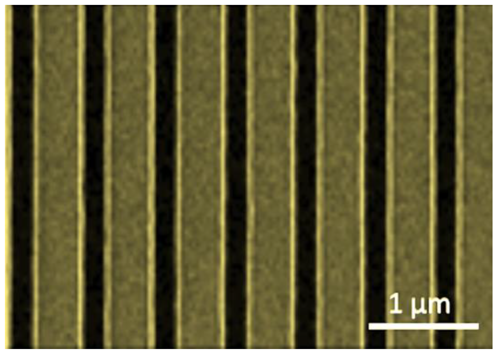
The main vertical inter-subband transition of this layer structure takes place at the desired energy, corresponding to a wavelength of 4 µm. In order to generate optical output radiation with a sufficiently small spectral linewidth and, thus, reasonably large coherence length, a single-mode light source is needed. The fabrication of this light emitter was, therefore, based on an optical diffraction grating defined at the interface between the top waveguide and the upper cladding layer. In order to perform dry etching of this diffraction grating, the epitaxial growth process needs to be interrupted after the top waveguide layer. For the fabrication of the grating, holographic exposure of a sufficiently thin photoresist layer using a two-beam interference setup (as described in reference [27]) is performed. Afterward, Cl2-based, inductively coupled plasma (ICP) etching is used to transfer the grating structure into the semiconductor [28]. With this technique, low etch damage, along with precisely vertical sidewalls, can be achieved. The first point is especially important because there will be an epitaxial regrowth after grating fabrication. A typical picture of the resulting grating before epitaxial regrowth with a period of Λ = 0.58 µm is shown in Figure 3 below [29,30]. As mentioned before, the 1.8 µm thick InP-based upper cladding and the highly n-doped 0.5 µm thick final cap layer will then be re-grown on top of the grating. Very similar devices are commercially available, for instance, from Alpes Lasers SA in St. Blaise (NE), Switzerland [31] and from DRS Daylight Solutions in San Diego, CA, USA [32,33].
For the definition and etching of the waveguide structures, standard photo-lithography, followed by a dry-etch process based on Cl2-chemistry, is used. The etch depth is supposed to reach slightly deeper (t = 5 µm) than the total epitaxial layer thickness of 4.5 µm. The wafer is then covered with a 200 nm thick Si3N4 electrical isolation layer. After the dry-etched opening of the electrical contact areas, the Ti/Au (10/500 nm) top metal layers are lift-off deposited. After bottom metallization Ge/Au/Ag/Au (10/25/50/350 nm), the cleaving of rectangularly shaped individual interferometer chips of 5 × 2 mm2 in size is performed.

3. Results

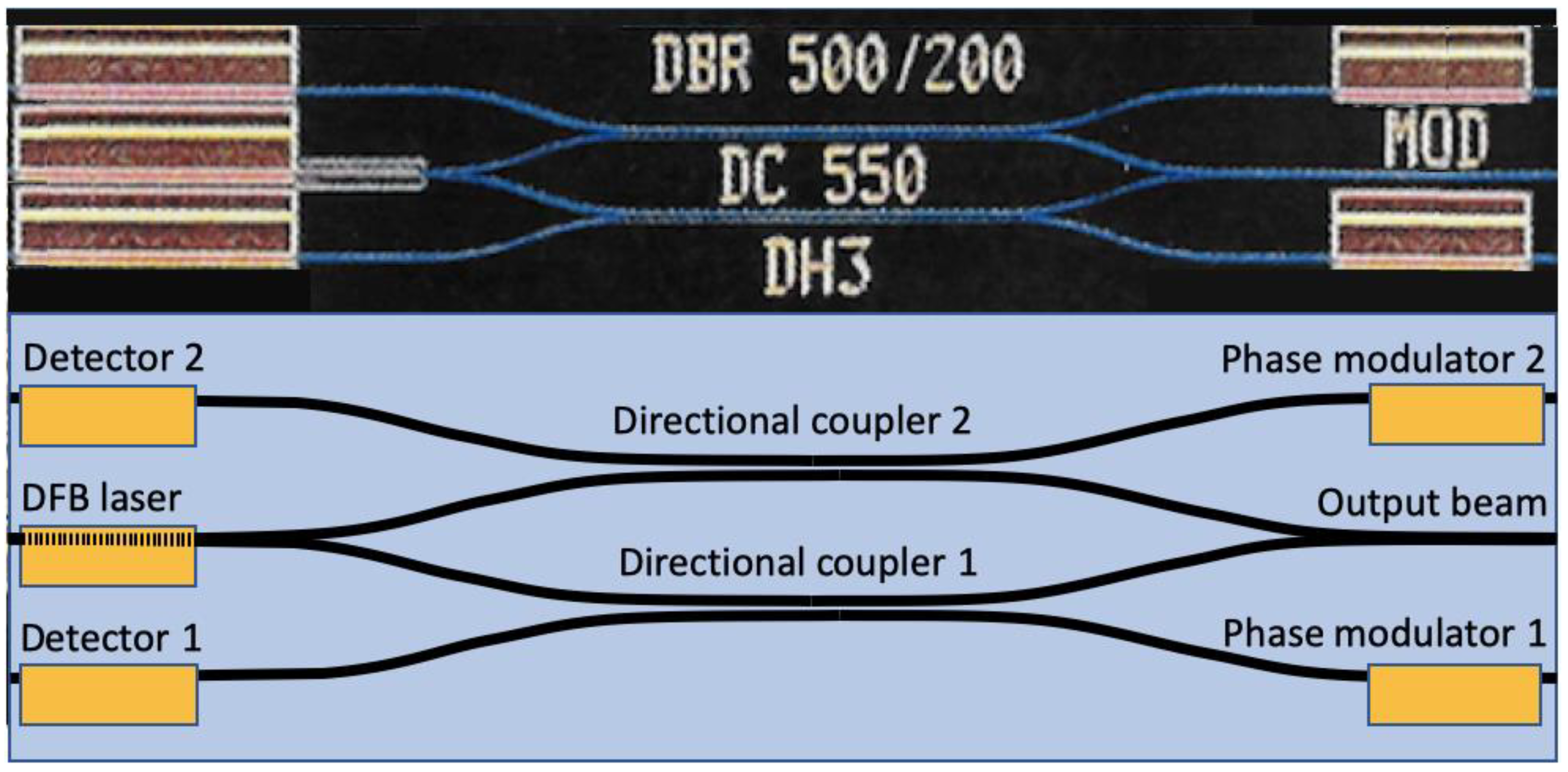
In the upper half of Figure 4, a microscope image of a Michelson interferometer—fabricated in 1996 using GaAs/AlGaAs technology—for a wavelength of λ = 0.82 µm is shown. In the lower part of Figure 4, a schematic drawing of a similar Michelson interferometer—as it was fabricated in this experiment—is presented. The only external element added to this integrated Michelson interferometer is a gradient index (GRIN) lens [34]. It is attached to the waveguide of the central output beam (sitting between the two phase modulators). Such GRIN lenses are not yet very common for the mid-IR wavelength range, yet there are several reports available in the scientific literature. Although such an element is not absolutely mandatory, its use nevertheless facilitates both interferometer alignment and operation [35].
In contrast to the experiment in 1996, the light source is a continuous-wave-operated DFB quantum cascade laser at a wavelength of 4 µm. As can be seen on the datasheet of such commercially available DFB lasers, linewidths of the order of ∆ν = 3 MHz are typically observed. This value corresponds to a coherence length of Lcoh = c/(π∆ν) ~ 30 m. Regarding the use of such a device for optical displacement measurements in CNC milling machines, the required maximum readings of 2 m can be achieved without any problem. In other words, assuming (for simplicity) a Gaussian linewidth profile of our laser source, the contrast of the corresponding interference fringes will show similar Gaussian decreasing behavior. At an equal length of both the reference and signal arms—corresponding to a vanishing relative mirror displacement—a maximal fringe contrast of m = 1 is seen. Going to a relative mirror displacement of ΔL = ±1 m then results in a very slight reduction in the contrast (m = 0.92) only.
On both sides adjacent to the single-mode DFB laser light source, two photodetectors labeled ‘Photodetector 1’ at the top and ‘Photodetector 2’ at the bottom are shown [36]. In order to opto-electronically isolate the active region of the laser and the two photodetectors, optical isolation trenches with a depth of twice the ridge waveguide height were etched. The 1996 experiment revealed the clear necessity for this additional feature. Otherwise, the photocurrent due to the optical crosstalk between the laser light source and the nearby photodetectors will quickly exceed the actually interesting interferometer signal by an order of magnitude. The digital photograph at the top of Figure 4 was made from an integrated Michelson interferometer using a DBR laser, and in the schematic drawing at the bottom, a DFB laser is proposed. It becomes clear from several publications in the scientific literature that a DFB laser profits from increased wavelength stability and considerably lower sensitivity against optical feedback effects. This is true even for a butt-joined DFB laser/waveguide pair, as was successfully demonstrated in reference [37]. When using (such as in 1996) a DBR laser, the only optical isolation against such unwanted feedback effects consists of a relatively strong diffraction grating. However, there existed no other design-inherent isolation; the correct functioning of the measurement chip was, therefore, based on a small amount of light (~10%) to be coupled out. Due to the inherent beam divergence in free space, there was, again, only ~10% found its way back into the laser. Slight deviations from the ideal coupling ratio might finally have resulted in another factor of 10%. The multiplication of these three small amounts resulted in sufficiently tiny feedback into the DBR laser. As a result, a relatively good beam quality, optical linewidth, and coherence length could be maintained. Table 3 below contains the extrapolated device parameters for each single component of this interferometer. Both waveguide width and separation are four times as large as in typical 820 nm laser diodes. Laser responsivity and detector sensitivity were taken from the previously mentioned publications [13,23].
The schematic drawing in the lower half of Figure 4 shows an integrated optical Michelson interferometer operating at 4 µm. Given a waveguide width of 8 µm, contact lengths between 500 and 800 µm, and a (larger) curvature radius of 1 mm, a chip size of 5 × 2 mm2 is envisaged here. The exact length of the directional coupler (ideally acting as a 50/50% beam splitter and working with TM (instead of TE)-polarized light) will have to be either numerically simulated or experimentally determined. For the time being, a tentative length of 450 µm is proposed. The gap between the two waveguides of the directional coupler should become roughly 4 µm. Another interesting question concerns the optimum geometrical dimensions and the absorption properties of the optical waveguides, the photodetectors, and the phase modulators. Their most critical parameters will ideally be defined by fabricating three different lengths, widths, or coupling strengths. Experimental measurements will then allow us to determine the most suitable device dimensions for each component. When assuming a CW QC laser output power of 100 mW, a QC detector sensitivity of 10 mA/W, a waveguide loss of 1 cm−1, a directional coupler efficiency approaching 10%, and input/output efficiencies of the order of 10% in each case, then a total AC signal amplitude of 1 µA can be expected.
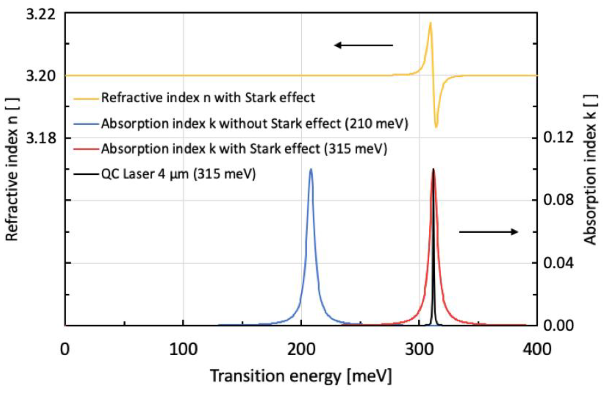
For a diode laser based on an interband transition, the bias applied on the active device will—via a pronounced quantum-confined Stark effect (QCSE)—result in a smaller transition energy than in the passive, unbiased areas. The energy of the emitted photons in the lasing area is, therefore, no longer sufficient to be absorbed in the unbiased waveguide area. This behavior was first described by D A B Miller et al. in 1984 [38]. The situation is, however, the opposite for the case of a laser based on an inter-subband transition. When an electric field is applied to such a QC laser-active region, the Stark shift results in a larger inter-subband transition energy [39,40]. If there were step-shaped absorption behavior, such as in a diode laser, the emission would, therefore, be strongly absorbed in the unbiased waveguide areas. However, unlike inter-band transitions, inter-subband transitions (such as in our case) exhibit peaked (i.e., not step-shaped) absorption. A biased ISB laser section will, therefore, shift its emission peak toward a slightly larger transition energy (red/black curves in Figure 5 below) than the absorption peak of the unbiased waveguides (blue curve in Figure 5 below). For a sufficiently small full width at half maximum (FWHM) in the ISB luminescence/absorption peaks (for instance, with an FWHM of 15 meV)—along with a large enough energy difference between the emission and absorption peaks—the mutual overlap between the biased laser/photodetector and unbiased waveguiding areas gets low enough to result in a small waveguide loss. An estimated loss value of αWG = 1 cm−1 then leads (after a 10 mm total path length (5 mm back and 5 mm forth) within the interferometer) to 37% of the initial intensity. At the same time, the unaltered high spectral overlap between laser emission and photodetector absorption will result in efficient absorption in the photodetecting section.
Within its linear range for an applied electric field of E = 0.32 V/47.8 nm = 6.7 × 10⁴ V/cm—according to reference [41,42]—the phase modulator (which is based on the QCSE) produces a refractive index change of ∆n = 1.0 × 10⁻³. In order not to overly stress the semiconductor material used, we work here—somewhat arbitrarily—with the known maximal field value being present in the active quantum cascade laser section [43,44]. With the above change in the refractive index, we can define a sufficiently long phase modulator to result in an optical phase shift of π/2 (i.e., π/4 per single pass). This condition is called phase quadrature. In order to calculate the required length of the modulator, let us first consider the angular argument of an electromagnetic wave having a wavelength of λ = 4.0 µm. Here, kλ is the wave vector defined by kλ = 2π/λ. We then compare the angular argument produced by a phase modulator with length L and having either a refractive index of ‘n’ or ‘n + Δn’. A refractive index of ‘n’ corresponds to an applied voltage of 0 V, and a refractive index of ‘n + Δn’ is seen at a maximum applied voltage of −10 V. Therefore, we obtain the following:
Δ φ [ ( n + Δ n ) ( n ) ] k λ   L = Δ n   k λ   L
Δ φ = ( 2 π   Δ n   L ) / λ
In addition, values of Δ φ = π/4 (π/2) for the desired single-pass (double-pass) optical phase shift, ∆n = 1.0 × 10⁻³ for the refractive index change within the linear range of Figure 5, λ = 4 µm for the wavelength of the DFB laser, and kλ = 1.5707 µm−1 are used [45]. With these parameters, Formula (2) can be solved for the yet unknown length, L, of the modulator:
L = ( λ   Δ φ ) / ( 2 π   Δ n ) = Δ φ / ( k λ   Δ n )
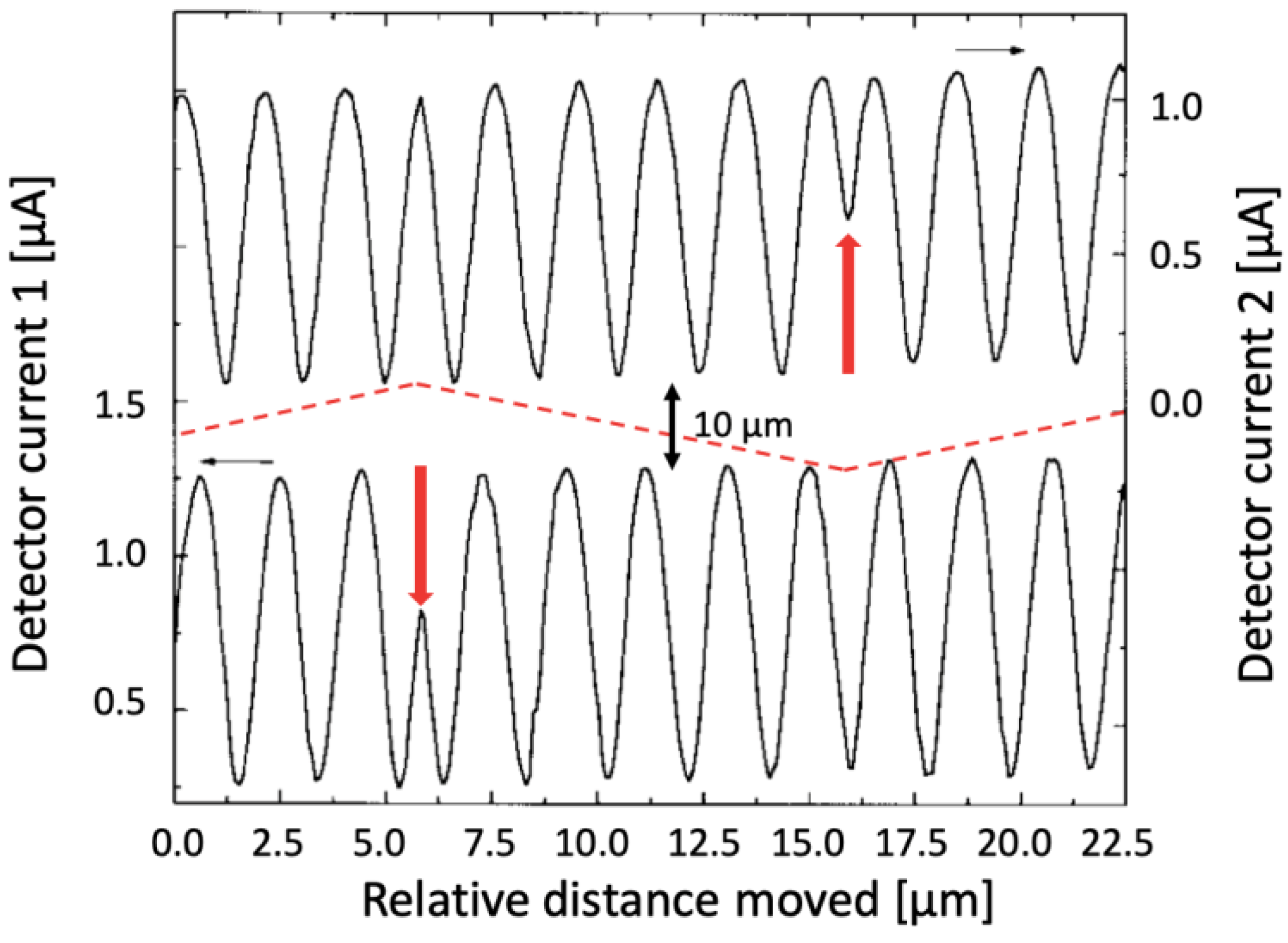
By using the above parameters, we obtained a value of L = 500 µm. Including a safety margin, we get L = 800 µm. In addition to its good manufacturability, this length still results in relatively low waveguide losses. Apart from the explicit calculation in Equation (2), most of the other results presented in this section are based either on numerical simulations or on experimental variations. In Figure 6, the signals of the two photodetectors located to the left and the right side of the DFB laser, respectively, are presented. The externally moving mirror travels roughly 10.5 µm in total between two extreme positions, which are 5.25 interference fringes apart.
The two discontinuities (red arrows) indicate the changes in direction of the external mirror. In addition to the current traces of the two interferometer signals in phase quadrature in Figure 6, these two signals will also be presented in the form of a so-called Lissajous figure. This more intuitive plot of the two measurement signals is shown in Figure 7. One interferometric fringe corresponds to half the employed laser wavelength; thus, it corresponds to 2 µm. Already, a minimal interpolation of four points per interference fringe (minimum, maximum, and two zeros in between) of this movement results in a measurement resolution of 500 nm. In Figure 7, we show the expected Lissajous figure of the sinusoidal/co-sinusoidal oscillations shown in Figure 6. For a mirror displacement in a given direction, the phasor of this roughly circular graph will turn in clockwise direction. If the sense of the mirror movement is reversed, the phasor in the Lissajous figure will turn in counter-clockwise direction accordingly.
Although the expected measurement resolution of 500 nm is five times lower (i.e., worse) than in our GaAs-based Michelson interferometer from 1996, it is still better than the presently used glass scale linear encoders by a factor of 10.
As shown in our earlier experiments from 1996, it is obvious that a shorter wavelength laser would—at least theoretically—allow for a considerably better measurement resolution. However, we must take into account the rather harsh environmental conditions typically prevailing in a mechanical workshop. They include oil vapors, metal chips, vibrations, and considerably large temperature changes. Under these somewhat difficult conditions, looking for a resolution far below 1 µm seems not to be very useful and rather overkill, resulting (eventually) in an increased number of problematic technical issues rather than satisfactory positioning precision. As an important difference to the results of 1996, the experiments suggested here are not made under idealized laboratory conditions or during vibration-free night hours. This easily explains why the relative resolution normalized by the laser wavelength has become five times lower.
Of course, knowledgeable people in the field might ask why mid-IR QC lasers have not been used much earlier for monolithic interferometers, especially since they were demonstrated already back in 1994 [21]. As a matter of fact, the first QC lasers were available only as cryogenically cooled devices. Room temperature CW operation with threshold currents in the several hundred mA range was achieved in 2002 [22]. True low-threshold currents have only been available since 2016 [46].

4. Discussion and Most Suitable Applications

In this publication, we propose the use of a monolithically integrated Michelson interferometer for optical displacement measurements—employing a QC DFB laser at an emission wavelength of 4 µm. Compared to existing interferometers that utilize near-infrared lasers at λ = 820 nm, this wavelength—and thus the resolution of the entire sensor circuit—will be coarser by a factor of five. However, in the main envisaged application (interferometric position measurement in CNC machine tools), the currently employed resolution will nevertheless be improved by roughly a factor of 10. Today, such machines typically use glass scale linear encoders, with a standard accuracy of 5 µm, whereas by using the interferometric method suggested in this publication, a positioning accuracy within 0.5 µm (i.e., 500 nm) will become possible. In Figure 8a, the existing measurement scheme based on such a glass scale linear encoder for current industrial applications is presented; Figure 8b shows a short section and enlarged details of such a linear encoder.
As written above, the linear accuracy of this very well-established positioning system is around 5 µm. In the following section, we will see how this accuracy can be improved by the use of an optical interferometer.
As mentioned before, very rough interpolation results in at least four points per period, i.e., a resolution of 500 nm. The arguments behind this number are based on the fact that the fringe distance corresponds to exactly one-half of the laser wavelength of 4 µm. Furthermore, by assuming that four points per fringe can be easily detected (the minimum, maximum, and two zeros of the sinusoidally modulated signal), we obtain a resolution of one-quarter of half the laser wavelength used. Although this resolution is five times ‘worse’ than in our GaAs-based Michelson interferometer from 1996—relative to the laser wavelength—it is still a factor of 10 better than the presently used glass scale linear encoder systems. In any case, it is clear that standard fabrication procedures and tolerances in mechanical workshops rarely reach below 10 µm. From this point of view, a positioning accuracy of 500 nm will be a really important step forward. Working with an even higher accuracy would, however, be truly overkill; parasitic effects, such as thermal and mechanical instabilities, in CNC machine tools would inherently prevent the successful implementation of such ultra-high positioning precision.
When finally looking at measurements in quantum metrology and investigating either entangled photons or detecting gravitational waves, due to its semiconductor laser light source, the suggested Michelson interferometer constitutes an emitter with too low spectral purity. With the proposed semiconductor-based interferometer having a typical coherence length of 30 m, the small effects in such highly specialized applications are simply not accessible.

5. Specific Use in Modern CNC Machine Tools

In today’s CNC machines (both for measuring and production purposes), high-precision positional readings based on glass scale linear encoders have been the industrial standard for several decades already. Such reading systems can be found, for instance, in DMG MORI AG milling machines. These machine tools are fabricated at the former Friedrich Deckel AG, Munich. One example of such a milling machine is shown in Figure 9 below.
Glass-based encoding systems—such as the one shown in the previous example—have a maximal accuracy of 5 µm. This has to do with mechanical ruggedness, temperature instabilities, and the smallest manufacturable feature size on such glass rulers. However, apart from mechanic CNC machines, glass scale linear encoders, such as the one in Figure 8, can also be found in metrology systems equipped, for instance, with the PICOSCALE Sensor Head of SmarAct, Inc. [48]. After all, there are numerous applications where a higher precision of the positional reading would be a clear advantage. In addition, the physical dimensions of the existing systems can no longer really be shrunk: a glass scale linear encoder with its tiny inscriptions needs a certain physical dimension, which corresponds pretty much to the maximal travel of the corresponding machine axis. If one could replace this bulky ruler element with a low-cost and touchless interferometer-based solution, this would be a formidable advantage. The interferometer proposed in this article is not overkill in terms of precision—owing to its long wavelength laser light source. Thanks to adequate housing, it will not be sensitive to oil vapors, metal chips, or other types of typical dirt that are generated in a mechanical workshop environment. With its factor-of-10 improvement of the expected accuracy, it constitutes a true improvement compared to existing glass scale linear encoding systems.

6. Use for Absolute Distance Measurements

The spectrometer presented in this publication also has the potential to be used as an absolute distance sensor. One method of choice for this purpose is frequency-modulated continuous-wave (FMCW) light detection and ranging (Lidar) [49]. With this method, a frequency-chirped, continuous-wave laser produces reflected waves from mirror-like surfaces. The required optical frequency shift is generated by an acousto-optic modulator. The aliasing-free beat signal produced by this method can then be used to extract the absolute distances of mirroring objects. As a rather advanced example, experimental demonstrations resulted in values of v = 26.43 ± 0.037 m/s for the velocity of a spinning disk at a distance of 1.267 ± 0.016 m. Furthermore, the system proposed in reference [44] above is capable of discriminating the direction of rotation based on a single fast Fourier transform analysis. In addition, a three-dimensional image of such a spinning disk can be reconstructed.

7. Conclusions

Resembling our earlier results from the year 1996 from using a GaAs-based monolithically integrated Michelson interferometer for optical displacement measurements, we propose a very similar device but with a five-times larger laser emission wavelength of 4 µm instead of 820 nm. For the typical applications envisaged here—namely, positional sensing in CNC machine tools—the resulting resolution when using mid-infrared light is still sufficiently high for most problems occurring in a mechanical workshop. As another important difference to the device demonstrated in 1996, a DFB laser instead of a DBR laser will be used. This results not only in a more straightforward fabrication procedure but also allows for more efficient optical isolation between the single-mode light source and the downstream interferometric circuit. This is an important issue because the GaAs-based displacement sensor from 1996 clearly ran into the problem of too high optical feedback entering into the DBR laser. This feedback led to a greatly increased laser linewidth and, thus, a much shorter coherence length of the DBR laser light source. In practical terms, this meant that our sensor could not be used for mirror distances larger than about 50 cm; in a typical mechanical CNC machine tool, such maximal mirror displacement would be clearly insufficient. With the suggested improvements, typical maximum displacements of ±1 m will be possible without problems. Obviously, the proposed interferometer will be suitable for any other high-precision measurement at the accessible distance range.

8. Patents

Since none of the contributing authors is currently working in the area of optical interferometry, there are no patent issues associated with this research.

Author Contributions

Conceptualization, D.H. and H.B.; methodology, D.H.; software, D.H. and H.B.; Writing—Original draft, D.H.; Writing—Review and editing, D.H., H.B. and D.P.B. All authors have read and agreed to the published version of the manuscript.

Funding

This research received no external funding.

Institutional Review Board Statement

Not applicable.

Informed Consent Statement

Not applicable.

Data Availability Statement

The original data are available from D.H. on request.

Acknowledgments

The authors would like to thank the former Institute of Physics at the University of Neuchâtel for having made their experimental equipment available; we express gratitude for the financial support provided by the Professorship Program of the Swiss National Science Foundation, and we acknowledge the valuable discussions with Klaus Reimann of the Max-Born Institute in Berlin and Manfred Helm from the Helmholtz-Zentrum Dresden-Rossendorf.

Conflicts of Interest

Author D.P.B. is employed by the company Google LLC and declares that this research was conducted in the absence of any commercial or financial relationships that could be construed as a potential conflict of interest. The authors D.H. and H.B. declare no conflicts of interest.

References

  1. Michelson, A.A. The relative motion of the earth and the luminiferous ether. Am. J. Sci. 1881, 22, 120–129. [Google Scholar] [CrossRef]
  2. Michelson, A.A.; Morley, E.W. On the relative motion of the earth and the luminiferous ether. Am. J. Sci. 1887, 34, 333–345. [Google Scholar] [CrossRef]
  3. Einstein, A. Zur Elektrodynamik bewegter Körper (in German). Ann. Der Phys. 1905, 322, 891–921. [Google Scholar] [CrossRef]
  4. Nolte, D.D. After the Gold Rush: The Trials of Albert Michelson. In Interference: The History of Optical Interferometry and the Scientists Who Tamed Light; Oxford University Press: Oxford, UK, 2023. [Google Scholar] [CrossRef]
  5. Cui, J.; He, Z.; Jiu, Y.; Tan, J.; Sun, T. Homodyne laser interferometer involving minimal quadrature phase error to obtain subnanometer nonlinearity. Appl. Opt. 2016, 55, 7086–7092. [Google Scholar] [CrossRef]
  6. Wang, J.; Cai, Z.; Yu, J.; Luo, H.; Ma, C. Nanometer-scale displacement measurement based on an orthogonal dual Michelson interferometer. Chin. Opt. Lett. 2023, 21, 101201. [Google Scholar] [CrossRef]
  7. Jestel, D.; Baus, A.; Voges, E. Integrated-optic interferometric microdisplacement sensor in glass with thermo-optic phase modulation. Electron. Lett. 1990, 26, 1144–1145. [Google Scholar] [CrossRef]
  8. Ulbers, G. A sensor for dimensional metrology with an interferometer using integrated optics technology. Measurement 1991, 9, 13–16. [Google Scholar] [CrossRef]
  9. Yuan, L.; Yang, J.; Liu, Z.; Sun, J. In-fiber integrated Michelson interferometer. Opt. Lett. 2006, 31, 2692–2694. [Google Scholar] [CrossRef] [PubMed]
  10. Feng, L.; Zhang, Q.; Lou, R.; He, S.; Yang, X. Fibre-optic Michelson interferometer for detecting coolant level and refractive index. Z. Für Naturforschung A 2022, 77, 621–627. [Google Scholar] [CrossRef]
  11. Suhara, T.; Taniguchi, T.; Uemukai, M.; Nishihara, H.; Hirata, T.; Iio, S.; Suehiro, M. Monolithic integrated-optic position/displacement sensor using wavguide gratings and QW-DFB laser. IEEE Photonics Technol. Lett. 1995, 7, 1195–1197. [Google Scholar] [CrossRef]
  12. Hofstetter, D.; Zappe, H.P.; Dändliker, R. Monolithically integrated optical displacement sensor in GaAs/AlGaAs. Electron. Lett. 1995, 31, 2121–2122. [Google Scholar] [CrossRef]
  13. Hofstetter, D.; Zappe, H.P.; Dändliker, R. Optical displacement measurement with GaAs/AlGaAs-based monolithically integrated Michelson interferometers. IEEE J. Light. Technol. 1997, 4, 663–670. [Google Scholar] [CrossRef]
  14. Englert, C.R.; Harlander, J.M.; Marr, K.D.; Harding, B.J.; Makela, J.J.; Fae, T.; Brown, C.M.; Ratnam, M.V.; Bhaskara Rao, S.V.; Immer, T.J. Michelson interferometer for global high-resolution thermospherical imaging (MIGHI) on-orbit wind observations: Data analysis and instrument performance. Space Sci. Rev. 2023, 219, 27. [Google Scholar] [CrossRef] [PubMed]
  15. Wang, G.; Song, Q.; Peng, H.; Xiao, Q.; Zhao, D.; Jia, B. Dual-wavelength Michelson interferometer employing time delay estimation for distributed disturbance location. Opt. Fiber Technol. 2020, 56, 102181. [Google Scholar] [CrossRef]
  16. Volkov, P.; Lukyanov, A.; Goryunov, A.; Semikov, D.; Vyazankin, O. Low-coherence homodyne interferometer for sub-megahertz fiber optic sensor readout. Sensors 2024, 24, 552. [Google Scholar] [CrossRef] [PubMed]
  17. Hu, X.-G.; Zhao, Y.; Peng, Y.; Tong, R.-J.; Zheng, H.-K.; Zhao, J.; Hu, S. In-fiber optofluidic Michelson interferometer for detecting small volume and low concentration chemicals with a fiber ring cavity laser. Sens. Actuators B Chem. 2022, 370, 132467. [Google Scholar] [CrossRef]
  18. Hei, K.; Anandarajah, K.; Martin, E.P.; Shi, G.; Anandarajah, P.M.; Bhattacharya, N. Absolute distance measurement with a gain-switched dual optical frequency comb. Opt. Express 2021, 29, 8108–8116. [Google Scholar] [CrossRef] [PubMed]
  19. Van den Berg, S.A.; van Eldik, S.; Bhattacharya, N. Mode-resolved frequency comb interferometry for high-accuracy long distance mesaurement. Sci. Rep. 2015, 5, 14661. [Google Scholar] [CrossRef] [PubMed]
  20. Volkov, P.; Lukyanov, A.; Goryunov, A.; Semikov, D.; Vopilkin, E.; Kraev, S. Fiber optic impact location system based on a tracking tandem low-coherence interferometer. Sensors 2023, 23, 772. [Google Scholar] [CrossRef] [PubMed]
  21. Faist, J.; Capasso, F.; Sivco, D.; Sirtori, C.; Hutchinson, A.L.; Cho, A.L. Quantum Cascade Laser. Science 1994, 264, 553–556. [Google Scholar] [CrossRef]
  22. Beck, M.; Hofstetter, D.; Aellen, T.; Faist, J.; Oesterle, U.; Ilegems, M.; Gini, E.; Melchior, H. Continuous-wave operation of a mid-infrared semiconductor laser at room temperature. Science 2002, 295, 301–305. [Google Scholar] [CrossRef] [PubMed]
  23. Jozwik, J.; Kuric, I.; Semotiuk, L. Laser interferometer diagnostics of CNC machine tools. Commun.-Sci. Lett. Univ. Žilina 2014, 16, 169–175. [Google Scholar] [CrossRef]
  24. Technical Description of an Existing Laser Interferometer for CNC-Machines in Mechanical Workshops. Lasertex Interferometer: Lasertex HPI-3D. 2024. Available online: https://lasertex.eu/products/dmi-hpi-3d/ (accessed on 20 May 2024).
  25. Yu, J.S.; Evans, A.; Slivken, S.; Darvish, S.M.; Razeghi, M. Short wavelength (λ ~ 4.3 µm) high-performance continuous-wave quantum-cascade lasers. IEEE Photonics Technol. Lett. 2005, 17, 1154–1156. [Google Scholar] [CrossRef]
  26. Hofstetter, D.; Beck, M.; Aellen, T.; Faist, J.; Oesterle, U.; Ilegems, M.; Gini, E.; Melchior, H. Distributed-feedback quantum cascade lasers emitting in the 9-µm band with InP top cladding layers. IEEE Photonics Technol. Lett. 2002, 14, 18–20. [Google Scholar] [CrossRef]
  27. Hofstetter, D.; Faist, J.; Beck, M.; Mueller, A.; Oesterle, U. Demonstration of high-performance 10.16 µm quantum cascade distributed feedback lasers fabricated without epitxial regrowth. Appl. Phys. Lett. 1999, 75, 665–667. [Google Scholar] [CrossRef]
  28. Ishutkin, S.; Arykov, V.; Yunusov, I.; Stepanenko, M.; Smirnov, V.; Troyan, O.; Zhidik, Y. The method of low-temperature ICP etching of InP/InGaAs heterostructures in Cl2-based plasma for integrated optics applications. Micromachines 2021, 12, 1535. [Google Scholar] [CrossRef]
  29. Hofstetter, D.; Beck, M.; Aellen, T.; Faist, J. High-temperature operation of distributed feedback quantum-cascade lasers at 5.3 µm. Appl. Phys. Lett. 2001, 78, 396–398. [Google Scholar] [CrossRef]
  30. Hofstetter, D.; Zappe, H.P.; Epler, J.E.; Söchtig, J. Single-growth-step GaAs/AlGaAs distributed Bragg reflector laser with holographically-defined recessed gratings. Electron. Lett. 1994, 30, 1858–1859. [Google Scholar] [CrossRef]
  31. Alpes Lasers SA, Avenue des Pâquiers 1, NE 2072 St. Blaise, Switzerland. Complete List of Available Room Temperature DFB Lasers. 2024. Available online: https://alpeslasers.ch/lasers-on-stock/sbcw10186.pdf (accessed on 17 April 2024).
  32. Lyakh, A.; Maulini, R.; Tsekoun, A.; Go, R.; Von der Porten, S.; Pflügl, C.; Diehl, L.; Capasso, F.; Patel, C.K.N. High-performance continuous-wave room temperature 4.0-µm quantum cascade lasers with single-facet optical emission exceeding 2 W. Proc. Natl. Acad. Sci. USA 2010, 107, 18799–18802. [Google Scholar] [CrossRef]
  33. DRS Daylight Solutions, 16465 Via Esprillo, San Diego, CA 92127, USA. 2023. Available online: https://daylightsolutions.com/products/CW-MHF/ (accessed on 21 June 2024).
  34. Kasztelanic, R.; Filipkowski, A.; Pysz, D.; Nguyen, H.T.; Stepien, R.; Liang, S.; Troles, J.; Karioja, P.; Buczynski, R. Development of gradient index microlenses for the broadband infrared range. Opt. Express 2022, 30, 2338–2352. [Google Scholar] [CrossRef]
  35. Zhang, C.; Gui, Y.; Xia, K.; Jia, G.; Liu, C.; Zhang, J.; Li, J.; Yang, Z. Preparation of infrared axial gradient refractive index lens based on powder stacking and the sintering thermal diffusion method. Opt. Mater. Express 2022, 12, 584–592. [Google Scholar] [CrossRef]
  36. Hofstetter, D.; Beck, M.; Faist, J. Quantum-cascade-laser structures as photodetectors. Appl. Phys. Lett. 2002, 81, 2683–2685. [Google Scholar] [CrossRef]
  37. Chen, X.F.; Liu, W.; An, J.M.; Liu, Y.; Xu, K.; Wang, X.; Liu, J.G.; Ji, Y.F.; Zhu, N.H. Photonic integrated technology for multi-wavelength laser emission. Chin. Sci. Bull. 2010, 56, 3064–3071. [Google Scholar] [CrossRef]
  38. Miller, D.A.B.; Chemla, D.S.; Damen, T.C.; Gossard, A.C.; Wiegmann, W.; Wood, T.H.; Burrus, C.A. Bandedge electroabsorption in quantum well structures: The quantum-confined Stark effect. Phys. Rev. Lett. 1984, 53, 2173–2177. [Google Scholar] [CrossRef]
  39. Harwit, A.; Harris, J.S., Jr. Obersvation of Stark shifts in quantum well intersubband transitions. Appl. Phys. Lett. 1987, 50, 685–687. [Google Scholar] [CrossRef]
  40. Bar-Joseph, I.; Klingshirn, C.; Miller, D.A.B.; Chemla, D.S.; Koren, U.; Miller, B.I. Quantum-confined Stark effect in InGaAs/InP quantum wells grown by organometallic vapor phase epitaxy. Appl. Phys. Lett. 1987, 50, 1010–1012. [Google Scholar] [CrossRef]
  41. Weiner, J.S.; Miller, D.A.B.; Chemla, D.S. Quadratic electro-optic effect due to the quantum-confined Stark effect in quantum wells. Appl. Phys. Lett. 1987, 50, 842–844. [Google Scholar] [CrossRef]
  42. Rocha, W.G.M.; Pilling, S. Determination of optical constants n and k of thin films from absorbance data using Kramers-Kronig relationship. Spectrochim. Acta Part A Mol. Biomol. Spectrocopy 2013, 123, 436–446. [Google Scholar] [CrossRef] [PubMed]
  43. Gross, E.; Nevet, A.; Pesach, A.; Monroy, E.; Schacham, S.; Orenstein, M.; Segev, M.; Bahir, G. Measuring the refractive index around intersubband transition in GaN/AlN multi quantum wells. Opt. Express 2013, 21, 3800–3808. [Google Scholar] [CrossRef] [PubMed]
  44. Almogy, G.; Shakouri, A.; Yariv, A. Observation of birefringence induced by intersubband transitions in quantum wells. Appl. Phys. Lett. 1993, 63, 2720–2722. [Google Scholar] [CrossRef]
  45. Huang, Y.-Z. Comparison of modal and material gain for strong guiding slab waveguides. IEE Proc. Optoelectron. 2001, 148, 131–133. [Google Scholar] [CrossRef]
  46. Wolf, J.M.; Riedi, S.; Süess, M.J.; Beck, M.; Faist, J. 3.36 µm single-mode quantum cascade laser with a dissipation below 250 mW. Opt. Express 2016, 24, 662–671. [Google Scholar] [CrossRef] [PubMed]
  47. Collins, D. Where Are Glass Scale Linear Encoders Used? Heidenhain Webpage 2022. Linear Motion Tips. Available online: https://www.heidenhain.com/products/linear-encoders/sealed/lc-100 (accessed on 3 May 2024).
  48. PICOSCALE Sensor Heads of ‘SmarAct’ Motion and Metrology Systems. 2024. Available online: https://www.smaract.com/en/picoscale-advantages (accessed on 20 May 2024).
  49. Na, Q.; Xie, Q.; Zhang, N.; Zhang, L.; Li, Y.; Chen, B.; Peng, T.; Zuo, G.; Zhuang, D.; Song, J. Optical frequency shifted FMCW Lidar system for unambiguous measurement of distance and velocity. Opt. Lasers Eng. 2023, 164, 107523. [Google Scholar] [CrossRef]
Figure 1. Drawing of the original Michelson interferometer used in the experiments of 1881/1887. In this figure, (a) is the sodium vapor light source, (b) is the 50% transparent glass plate acting as a beam splitter, (c) and (d) are silver-coated mirror glass plates, (e) is the ocular for fringe observation, (g) is a compensating plane-parallel glass plate, (k) and (l) are the signal and the reference arms of the interferometer, respectively, and (m) is a micrometer screw acting on plate (b); (u) is a counterweight for the mechanical stabilization of the entire setup, and (o) is a circularly shaped supporting plate for the different interferometer components. This picture was copied from reference [2].
Photonics 11 00593 g001
Figure 2. Modern laser interferometer of a mechanical milling machine. It is obvious that, in comparison to the proposed monolithically integrated Michelson interferometer, a larger space budget must be reserved for such a bulky system. In this example, the external mirror is attached to the moving rotary table, and the interferometer itself sits in the box attached to the machine bench.
Photonics 11 00593 g002
Figure 3. Optical diffraction grating to be etched by an inductively coupled plasma (ICP) process between the top waveguide (In0.53Ga0.47As) and the upper cladding (InP) layer. The required grating period is 0.58 µm. An etch depth of 100 nm is realized in this device. The upper cladding and the cap layers are then epitaxially regrown on top of the grating.
Photonics 11 00593 g003
Figure 4. The picture at the top is an optical microscope image of a monolithically integrated Michelson interferometer fabricated and characterized in 1996. The laser wavelength used in this device was 0.82 µm, i.e., about five times smaller than the one in the work proposed herein. The schematic picture at the bottom shows the Michelson interferometer proposed. Due to the longer laser wavelength, larger curve radii were used. The device, therefore, measures 5 mm in length.
Photonics 11 00593 g004
Figure 5. Refractive and absorption index of a 500 µm long phase modulator based on the QCSE. With this length, a single-pass phase shift of π/4 (phase quadrature in double-pass) between the two interferometer signals can be achieved. Here, we assume a grating coupling efficiency of z = 10%. The upper arrow—pointing towards the left y-axis—belongs to the upper (yellow) ‘Refractive index n’ curve (plotted on the left). The lower arrow—pointing towards the right y-axis—belongs to the lower (blue, red, black) ‘Absorption index k’ curves (plotted on the right).
Photonics 11 00593 g005
Figure 6. Measured photocurrents of a monolithically integrated Michelson interferometer in the 4 µm wavelength range. The dashed red line shows the periodic 10.50 µm movement of the external mirror. The two red arrows at x = 5.75 µm and x = 16.25 µm mark the positions where this movement was reversed after each 5.25 interference fringes; corresponding to 2.00 µm per fringe.
Photonics 11 00593 g006
Figure 7. Lissajous figure of the measured relative photocurrents occurring in photodetector 1 (plotted on the x-axis) and photodetector 2 (plotted on the y-axis). In practice, due to some remaining electro-optical crosstalk, certain DC current offsets will occur. Even with a deep trench between the laser and detector waveguides, and when using metalized trench sidewalls, optical radiation finds its way directly into the photodetectors. In a carefully designed and ideally fabricated trench, we expect parasitic unmodulated crosstalk currents of the order of <1 µA.
Photonics 11 00593 g007
Figure 8. Schematic view (a) and short section (b) of a glass scale linear encoder, as is used today in state-of-the-art CNC machines. Such encoders have a positioning accuracy of 5 µm [47]. (1) LED light source, (2) condenser lens, (3) slit mask, (4) glass ruler, and (5) photodetectors.
Photonics 11 00593 g008
Figure 9. Refurbished DMG MORI AG milling machine. This type of machine is already fitted with glass scale linear encoders in the three main axes, with each having an accuracy of 5 µm. Fortunately, in each one of the three main directions, there is a sufficiently large amount of space to add a movable mirror and a fixed InGaAs/InAlAs-based, monolithically integrated interferometer chip.
Photonics 11 00593 g009
Table 1. Generic layer descriptions, materials, thicknesses, and doping levels of the proposed Michelson interferometer.
Layer DescriptionsMaterialsThicknessesDoping Levels
Cap layerInP0.5 µmSi, 2 × 1019 cm−3
Upper cladInP1.8 µmSi, 2 × 1017 cm−3
GratingIn0.53Ga0.47As0.2 µmSi, 5 × 1017 cm−3
Upper waveguideIn0.53Ga0.47As0.3 µmSi, 8 × 1016 cm−3
Active regionIn0.68Ga0.32As/In0.39Al0.61As1.4 µmSi, 1 × 1017 cm−3
Lower waveguideIn0.53Ga0.47As0.3 µmSi, 8 × 1016 cm−3
SubstrateInPSi, 6 × 1016 cm−3
Table 2. Type of epitaxial layers, along with the materials, thicknesses, and doping levels for 1 of the 30 totally active region periods [25,26].
Layer DescriptionsMaterialsThicknessesDoping Levels
Barrier 1/QW 1In0.39Al0.61As/In0.68Ga0.32As41 Å/10 Å
Barrier 2/QW 2In0.39Al0.61As/In0.68Ga0.32As15 Å/39 Å
Barrier 3/QW 3In0.39Al0.61As/In0.68Ga0.32As15 Å/34 Å
Barrier 4/QW 4In0.39Al0.61As/In0.68Ga0.32As16 Å/31 Å
Barrier 5/QW 5In0.39Al0.61As/In0.68Ga0.32As23 Å/23 Å
Barrier 6/QW 6In0.39Al0.61As/In0.68Ga0.32As18 Å/20 Å
Barrier 7/QW 7In0.39Al0.61As/In0.68Ga0.32As19 Å/18 ÅSi, 1 × 1017 cm−3
Barrier 8/QW 8In0.39Al0.61As/In0.68Ga0.32As20 Å/17 ÅSi, 1 × 1017 cm−3
Barrier 9/QW 9In0.39Al0.61As/In0.68Ga0.32As22 Å/16 Å
Barrier 10/QW 10In0.39Al0.61As/In0.68Ga0.32As22 Å/15 Å
Barrier 11/QW 11In0.39Al0.61As/In0.68Ga0.32As29 Å/15 Å
Table 3. The waveguide dimensions and several specific device parameters of the components in this work.
ComponentWidthLengthLossSeparationSplittingSensitivityResponsivity
Waveguide8 µm5 mm1 cm−1
DFB-Laser8 µm500 µm10 cm−1100 mW/A
Directional Coupler8 µm450 µm1 cm−14 µm50%/50%
Phase Modulator8 µm800 µm1 cm−1
Photodetector8 µm500 µm10 cm−110 mA/W
Disclaimer/Publisher’s Note: The statements, opinions and data contained in all publications are solely those of the individual author(s) and contributor(s) and not of MDPI and/or the editor(s). MDPI and/or the editor(s) disclaim responsibility for any injury to people or property resulting from any ideas, methods, instructions or products referred to in the content.