Article

Design of Photonic Molecule-Based Multiway Beam Splitter/Coupler with Variable Division Ratio

V.E. Zuev Institute of Atmospheric Optics, 1 Acad. Zuev Square, Tomsk 634021, Russia
Photonics 2024, 11(7), 600; https://doi.org/10.3390/photonics11070600
Submission received: 30 May 2024 / Revised: 24 June 2024 / Accepted: 25 June 2024 / Published: 26 June 2024
(This article belongs to the Special Issue Recent Advances in Diffractive Optics)

Abstract

:
An optical beam splitter is used for dividing an input optical beam into several separate beams with a specific power ratio. Usually, conventional optical beam splitters have bulky dimensions (many optical wavelengths) and a fixed dividing ratio, which significantly limit the design of new miniaturized optical devices and integrated optical circuits. We propose and investigate in detail a novel physical concept of a highly miniaturized (up to two working wavelengths) planar optical resonant splitter/coupler with a switching element comprising a photonic molecule (PM) pair dispersing input optical fluxes in multiple directions with a tailored power ratio. The structural design of the proposed splitter is based on a silicon-on-insulator (SOI) platform and composed of high-quality resonators in the form of electromagnetically coupled submicron-sized microcylinders. The control on the power division ratio and the selection of optical beam directions is realized by tuning the photonic splitter structure to the corresponding resonance of the PM supermode. Compared to known analogs, the proposed design is easy and cheap in fabrication. Because of its tiny dimensions, it is suitable for integration into a “System-on-a-chip” platform and can dynamically change the beam power division ratio by input wave-phase manipulation.

1. Introduction

Dielectric microresonators have long been actively used in disk lasers [1], high-resolution spectroscopy [2], laser frequency stabilization [3], add–drop filters for compact wavelength division (de)multiplexing [4,5], dispersion compensation of optical fiber transmission lines [6], implementation of all-optical switching for optical signals [7,8], optical nodes of quantum computers [9], as well as beam power dividers [10,11] and inertia-free optical couplers [12,13].
Generally, an optical beam splitter (BS) is a device for splitting an optical beam incident on its input port into two or more separate beam(s) with specific power ratio(s) and optionally field polarization states and phase matching. Typically, glass plates or prisms with semi-reflective coatings are used in the design of beam splitters. However, in the spatial scales of nanophotonic devices, as well as in the geometry of planar on-chip optical elements, the bulky dimensions of conventional beam splitters, which usually constitute many optical wavelengths, and their constructively predetermined fixed power division ratio significantly limit the design of new miniaturized optical devices and make it difficult to build integrated optical circuits. This challenge has stimulated the development of BS devices based not on the differential refraction of optical fluxes but on the principle of diffraction division of an input optical signal into separate beamlets by interaction (transmission) with specially designed diffractive optical elements (DOEs). Thus, such DOEs can be, e.g., ring resonators integrated into photonic crystals [14,15], specially shaped reflecting/transmitting metasurfaces and meta-lattices [11,16,17] providing angular beam separation, as well as planar conventional Y-branch splitters with a complex hierarchy [18].
Recently, optical splitters based on planar disk or ring traveling/standing wave resonators realized as an integrated element inside photonic crystals [8,15] or directly on a silicon-on-insulator (SOI) platform [4,5,19] have become widespread. Typically, such splitters operate in a narrow spectral band near the eigenmode resonances of a constituting microcavity when the incoming optical radiation is coupled to the resonant modes and is redirected into signal collection channels (drop ports). The main advantages of such BS devices are their planar design suitable for operation directly as part of a photonic SOI microchip, as well as low insertion losses of the optical signal, typically <−8 dB. Another profit of resonance-based dividers is that they can function as narrow passband filters allowing for an optical signal passing only within the resonance contour of a particular cavity eigenmode.
The most common structural design of resonant beam splitters (RBSs) is usually composed of several high-quality (high-Q) resonant DOEs (ring, disk, microcylinder, microsphere) coupled to the commutation buses in the form of rectangular or cylindrical waveguides forming the through and drop ports of the optical signal output. The resonators themselves are usually in close subwavelength contact with each other in a serial [4] or parallel structural topology [5,20]. The working principle of a typical RBS relies on resonant excitation of specific resonator eigenmode(s) which, ideally, captures all optical energy in the through port(s) and blocks forward optical wave propagation, but redirects the optical energy to the drop channel(s) that is usually connected to the other side of the resonance cavity [5,14]. In optical splitters based on multimode interaction, the interconnection of resonant elements and waveguide buses is realized by indirect coupling of evanescent electromagnetic fields of the eigenmodes. The presence of several resonators in the RBS design improves its filtering properties. Meanwhile, the topologies of dividers and couplers with nested [21] and cascade-arranged microrings [22] are also reported, which increase the sensitivity of the device.
Recently, specific photonic structures—photonic molecules (PMs) formed by electromagnetic coupling of two or more optical microcavities—have gained increasing scientific interest [23,24]. This physical molecular analogy stems from the special optical PM properties, which are themselves manifested in the fact that the normal electromagnetic modes of a PM are constituted of several interacting “photonic atoms”, and the electronic states of real atoms of matter combined into a molecule behave in a similar way. In other words, a single optical resonator is treated as a photonic atom, while several optically coupled resonators are treated as the photonic analog of a matter molecule. With these high-dimensionality of composite structures, controlled interactions between light and matter can be achieved and even enhanced by manipulating the coupling or matching of individual resonators, including their mechanical and optical tuning [25,26,27].
To date, quite a few different topological forms of PMs are studied, including basic diatomic molecules, molecular chains, and complex 2D structures [28]. Meanwhile, a common property of all PMs is the appearance of specific structural electromagnetic superlattice modes, usually referred to as the supermodes (SMs), resulting from the collective resonant interaction of the optical fields of all atoms in a photonic molecule [29]. This strong mode coupling produces a new hybridized spectrum of eigenfrequencies of molecular photonic structure as a whole [26]. PM supermodes differ in the type of optical coupling of atoms and form bonding (even) and anti-bonding (odd) oscillations, which results in the corresponding symmetry or anti-symmetry in the electric field’s distribution with respect to the PM axis [30]. In addition, with the change in the type of interatomic coupling, the quality factor (Q) of PM supermodes also changes, in some cases demonstrating a drastic increase relative to the Q-value of an isolated resonator [25,31].
Typically, photonic molecules are excited using a single optical channel through a PM matched tapered fiber [26], or by illuminating the molecule with free-space coupled radiation [32]. Recently, in our work [31], a scheme simultaneously using two optical buses with varying phase difference was proposed to enhance or suppress the generation of certain supermodes of the molecule and thus control its spectral response. According to the structural parameters, the photonic molecules consisting of planar resonators are similar to the resonant beam splitters discussed here. Both photonic structures have coupling resonant cavities and excitation/emission channels. Regarding this connection, however, the possibility of using PMs with complex topology possessing a rich spectrum of supermodes as an element of RBS has not yet been discussed in the literature.
In this paper, we propose a new theoretical concept of a resonant optical beam power splitter based on photonic molecules (PM-BS) with different topologies. We consider a PM formed by quazi-planar resonators in the form of several silicon microcylinders with subwavelength thickness. The main advantage of the proposed PM-based optical splitter over known analogs is its multiway operation, which allows for redirecting the input optical signal into several oppositely directed drop channels with a tailored power ratio. Additionally, by adding another input channel, the PM-based beam splitter can function as an optical coupler, which mixes signals from the input ports and directs them to one or more output channels. Unlike similar metasurface-based beam dividers [11,33], in terms of functionality, the proposed beam splitter is much simpler and cheaper in fabrication, suitable for “System-on-a-chip” integration, and can dynamically change its power splitting ratio by spectrally tuning to a different resonant supermode of the constituting PM. Moreover, another advantage of the proposed RBS is its ultracompact design, with the switching area dimensions typically not exceeding few optical wavelengths as compared to the optical splitter based on ring resonators and Y-junctions [5,34].

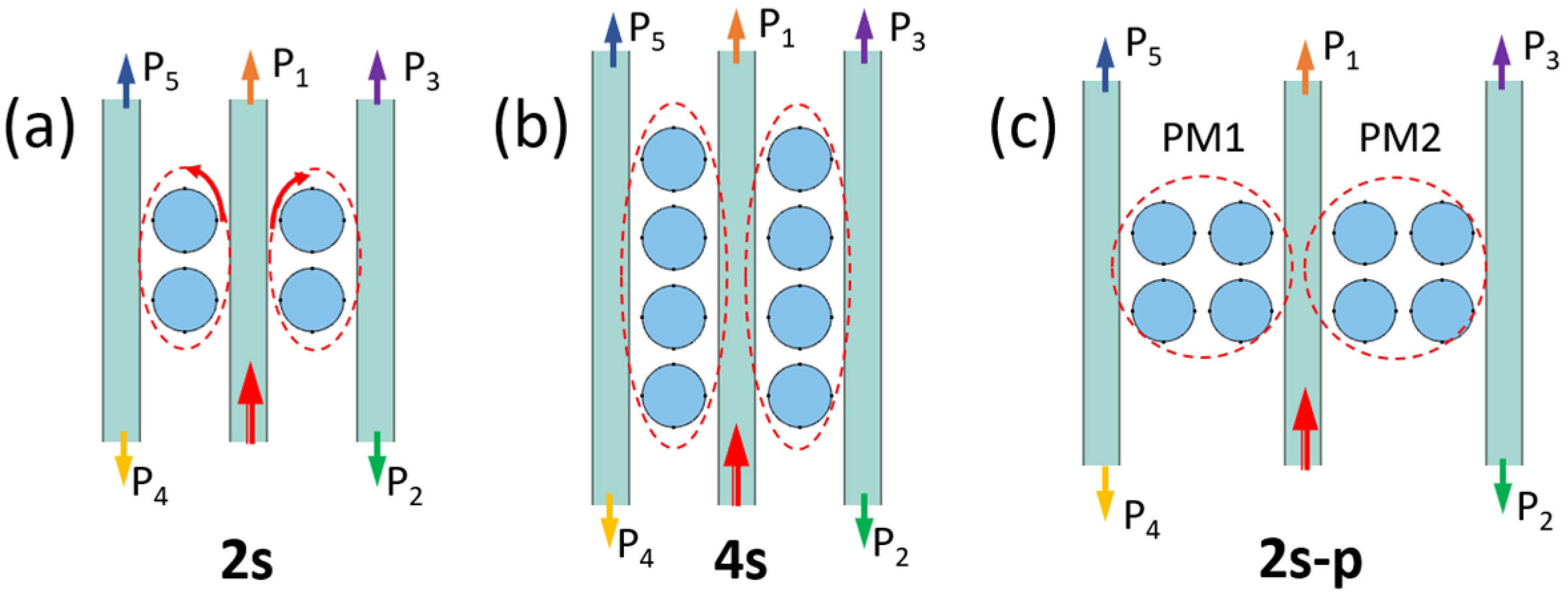
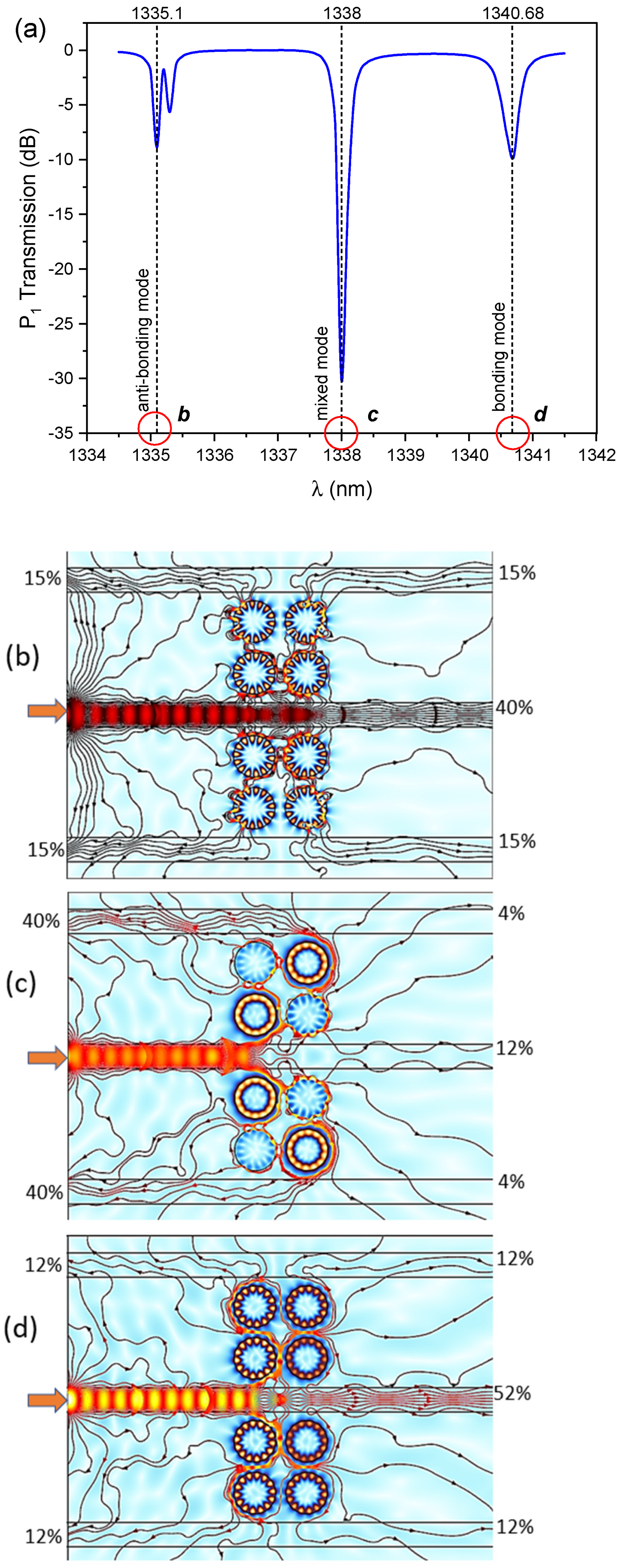
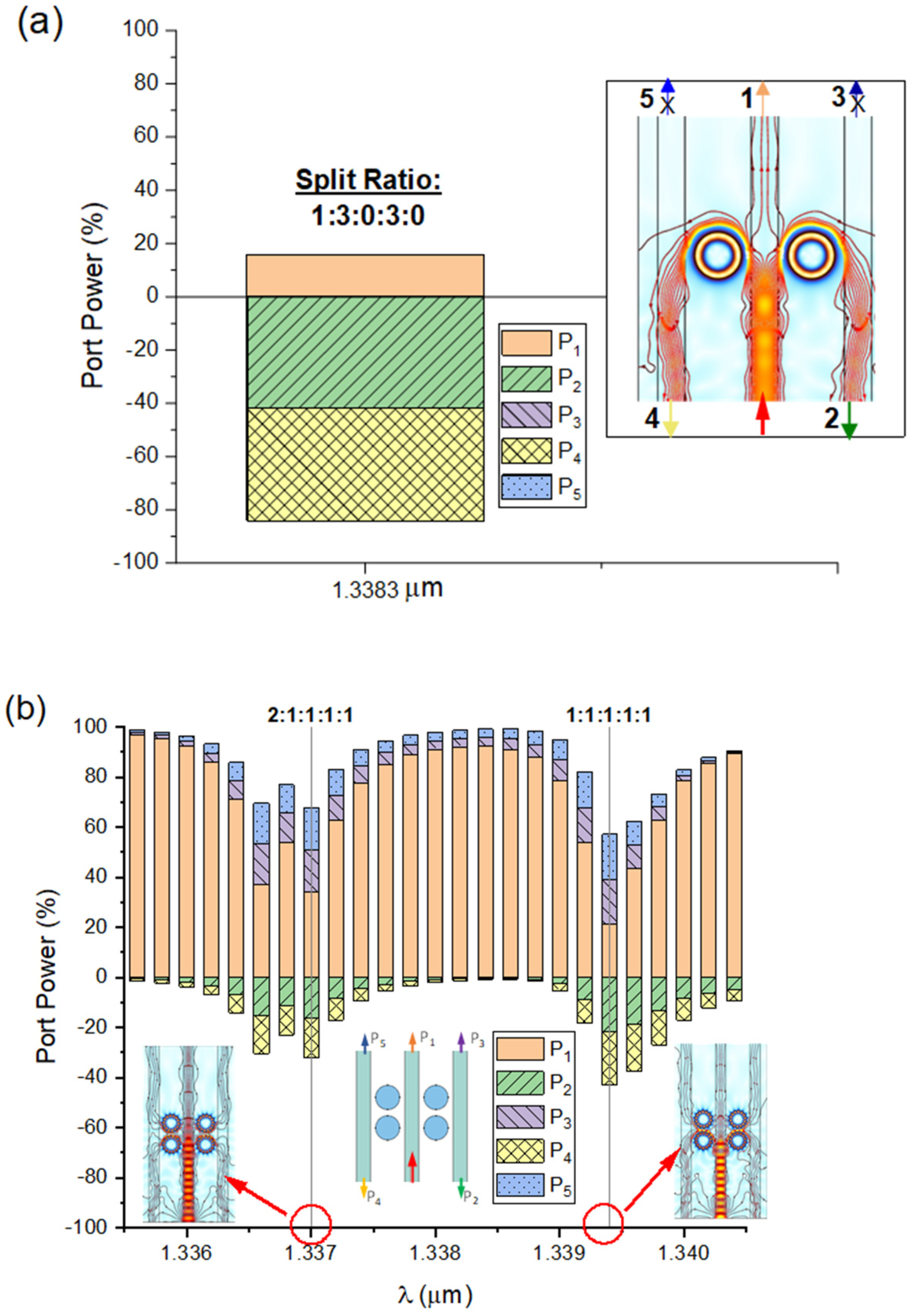
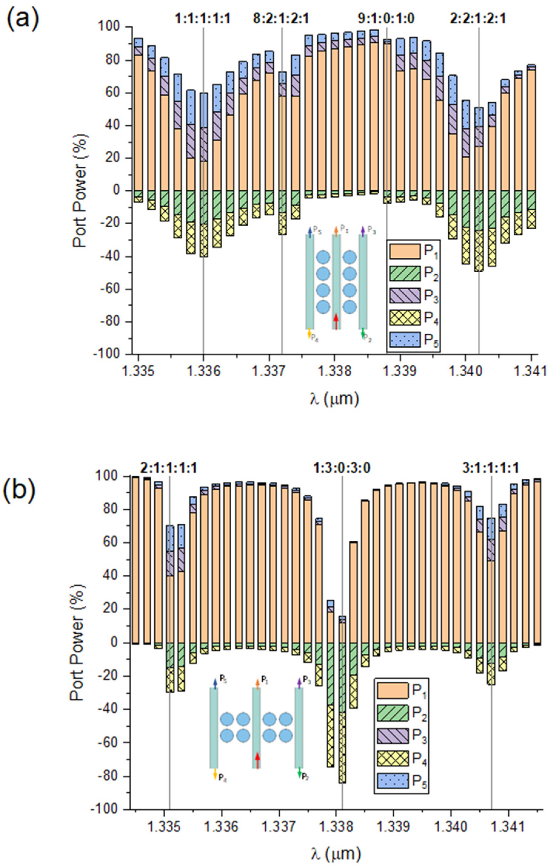
2. PM-BS Structural Model and Working Principle

Before considering complex PM-based beam splitter structures, it is instructive to recall the basics of coupled oscillations in the simplest system of two closely spaced identical resonant cavities (atoms) pumped through two optical waveguide channels, as shown in Figure 1a.
Assume that each cavity in the pair supports a single degenerate optical eigenmode at the same frequency ω0. By using the coupled mode theory [35], the evolution in time (t) of two eigenmodes a1 and a2 existing in a cavity pair is described by the following equations:
d d t a 1 = j ω 0 μ i + μ w a 1 + A μ w e j Δ φ j μ c a 2 d d t a 2 = j ω 0 μ i + μ w a 2 + A μ w j μ c a 1
Here, μi is field amplitude decrement due to intrinsic losses in the cavity (absorption, radiative escape, etc.), μw and μc stay for normalized coupling parameters of resonators with a waveguide and with each other, respectively. Obviously, the inter-cavity coupling μc depends on the value of the interatom gap (g). In the following, for simplicity, we take A = 1, and then the solution to Equation (1) for any of the normal modes, e.g., a1, can be written as follows:
a 1 t e μ t t j μ c ω 0 + μ t e j Δ φ 1 e j ω 0 + μ c t j μ c + ω 0 μ t e j Δ φ + 1 e j ω 0 μ c t
where μt = (μI + μw) and j2 = −1.
Equation (2) shows that a pair of coupled resonators instead of a single resonant mode ω0 possess two collective resonances—the supermodes—with the eigenfrequencies, ω1,2 = ω0 ± μc, equidistantly shifted from the resonant frequency of the isolated cavity by the value of the coupling coefficient μc and having the power ratio a 1 2 / a 2 2 μ c ω 0 2 / μ c + ω 0 2 . At the same time, the magnitude of the phase shift Δφ between the excitation channels of the photonic duet controls the amplitudes of these supermodes. Particularly, in two extreme cases, Δφ = 2πm and Δφ = (2m + 1)π, where m is an integer, the anti-bounding or bounding modes are completely suppressed, respectively. Importantly, the dips in the PM waveguide transmittances in Figure 1b indicate that almost all incoming optical power is trapped in PM supermodes maintaining the energy recirculation along the resonators’ surface. If yet another optical waveguide (drop port) is placed in the gap between the atoms, it can capture part of the SM energy and redirect out of the photonic molecule, thus forming a drop channel. Qualitatively, this is the way a PM-based splitter/coupler works.
Without reducing the generality of the problem considered, we further analyze a certain PM topology built from identical photonic atoms in the form of a circular cylinder of a certain diameter, say, D = 1200 nm, and height, h = 600 nm, placed in the nodes of a rectangular 2D lattice with the period d = 1270 nm. Different numbers of PM atoms can form photonic structures with either two or four interacting resonators. According to the physical type of this optical field coupling, we refer to the serial arrangement of atoms as “2s” and “4s” configurations, as depicted in Figure 2a,b, whereas a mixed type of serial–parallel bonding is labeled as “2s-p” molecule and shown in Figure 2c.
In the simulations, a PM is assembled on the SOI platform with a silicon dioxide (SiO2) substrate and is structurally characterized by the interatomic gap, g = 300 nm. Crystalline silicon (Si) with refractive index n = 3.5 and almost zero optical absorption (κ ~ 10−11) in the telecommunication spectral band centered on the wavelength λ = 1330 nm [34] is chosen as the material for photonic atoms. To enhance functionality, the considered photonic splitter is composed of two PMs coupled through a central waveguide (Figure 3a,c) acting as an input port. On the lateral sides of the splitter structure, two more waveguides are mounted at a certain distance (s) from the outermost atoms, s = 250 nm, serving for the collection of the divided optical beams. All waveguide feeders are considered to have the same width (1000 nm) and height (600 nm) and can be fabricated from the core of a single-mode optical fiber (SiO2), or through the etching of a dielectric photoresist (e.g., PMMA). The refractive index of the waveguides during the simulation was chosen as n1 = 1.5.
An optical TE-polarized wave (Figure 3d) with an electric field vector directed along the z-axis (out of the plane of the figure) is fed to the input of the splitter. After interacting with the resonant structure (PMs), the split optical fluxes are captured by through and drop ports 1 to 5. When operating as a coupler (Figure 3b), the operation order of the optical ports is reversed. Now, ports 4 and 2 become the input ports and the remaining ports become signal acquisition ports. Importantly, every molecular structure considered in this paper can operate both as a beam splitter and a beam coupler depending on the port switching order.
The spectral range of the input wave is chosen to include one of the high-Q eigenmode resonances of the cylindrical atom constituting a PM. This resonant mode exists in the form of a standing or traveling wave and is often referred to as the “whispering-gallery mode” (WGM) [36]. In order for the PM to function as a coherent resonant photonic structure, it is necessary to require sufficiently high-Q values of the microcavity used to ensure the WGM excitation. Since the surface of a dielectric atom is not totally reflective, the optical fields of the eigenmodes leak out the resonator boundaries and in this sense the WGMs in an open resonator are the quasi-bounded or quasi-normal electromagnetic modes. The optical coupling between the PM atoms is precisely due to these leaking evanescent fields [37]. Thus, in the situation considered, the eigenmode TE7,1 in a silicon cylinder is chosen as the fundamental resonance (Figure 3d) having quality factor Q = 8500 at the wavelength λ = 1338.2 nm and the linewidth of about 0.2 nm. Note that, according to the adopted notations for the electromagnetic eigenmodes of a sphere, the subscripts “7,1” denote the semi-number of optical standing wave antinodes along the azimuthal direction (along the cylinder rim) and the number of maxima along the radial coordinate, respectively.
For studying the spatial distribution of the optical field in the photonic structures considered, we apply the vector Helmholtz equation in the stationary approximation:
× × E r k 2 ε r E r = 0
Here, ε is the dielectric permittivity of medium and k = 2π/λ is the optical wavenumber. The electric field E is a vector with the components along each of the coordinate axes. Worthwhile noting, in the case of a spherical or cylindrical particle, the analytical solution to Equation (3) is widely known in the form of infinite series on the vector spherical harmonics, called the “Mie series” in the literature [38]. For two or more touching particles, although such partial wave expansion can be obtained and used (T-matrix method [39], multisphere scattering formulation [40], discrete dipole approximation [41]), it results in too sophisticated a formulation and is time/memory consuming in the calculations. Therefore, in the following, we use the direct numerical integration of the wave Equation (3) to derive the electromagnetic field distribution.
The numerical solution of the Helmholtz equation (3) for the electromagnetic field in the investigated photonic structure is performed using the Wave Optics module of COMSOL Multiphysics® 5.1 software, which exploits the finite element method (FEM). Without limiting the generality, we use the 2D formulation of the problem as shown in Figure 3c,d. In this case, the whole photonic structure is surrounded by a rectangular region of perfectly absorbing layers (PMLs) to minimize wave reflection from the boundaries. The optical radiation is input through the corresponding COMSOL digital ports. For the numerical discretization of all simulation domains, a mesh with triangular elements and a maximum edge size of λ/40 is used. The wavelength sweep is performed by creating a parametric study in the range of 1333 nm ≤ λ ≤ 1343 nm, which includes all supermodes of the considered PM topologies based on the TE7,1 resonance of single atom.
To understand the PM-BS operation principle, we consider the resonance spectrum of a 2s-p molecule, which is shown in Figure 4a as the spectral dependence of P1-port transmittance. As seen, the spectrum of such a molecule contains a total of 4 collective supermodes, each of them being fourfold degenerate due to the high spatial symmetry in the PM atomic structure. Here, three groups of resonant supermodes can be distinguished [31]: (i) anti-bonded modes with λ = 1335.1 nm and 1335.3 nm, (ii) bonded modes with λ = 1340.68 nm, and (iii) a mixed-type supermode centered at λ = 1338 nm. The blue-shifted anti-bonded modes have close resonance wavelengths, so in the following, we consider the only one of them, with λ = 1335.1 nm, which exhibits more pronounced transmission dip.
In the anti-bonded molecular supermode the phases of field oscillations in all atoms are opposite and mirror-symmetric with respect to the symmetry axis of the molecule [42]. Practically, the anti-bonded supermode can be considered as the eigenmode resonance of the half-PM located near a perfectly reflecting mirror. Previously [43], in the example of a dielectric sphere on a mirror, it was shown that in this case, the blue shift in TE-mode resonance is realized. A similar effect is observed for the anti-bonded supermode of a photonic molecule. In contrast, the bonded supermode is red-shifted within the PM spectrum and demonstrates the appearance of strong bonds between electric fields of atoms. As in an ordinary molecule of matter, a PM exhibits strong interference and hybridization of optical eigenmodes (molecular energy terms), which is expressed in mode splitting and the appearance of new collective field oscillations (low-energy sublevels). The mixed-type PM supermode bears the imprint of both bounded and anti-bounded modes, and the distribution of interatomic optical fields here is characterized simultaneously by symmetry along one direction and anti-symmetry with respect to another plane.
In Figure 4b, the streamlines of the Poynting vector, defined as S = c / 8 π Re E × H * (E and H are electric and magnetic field vectors, respectively, and c is the speed of light), are plotted for each of the selected supermodes. As seen, in resonance, the streamlines of vector S are captured from the feeder waveguide by nearby atoms of the molecule and then directed into the hybridized field of the PM supermode formed by the coupling of atomic resonant modes. Photonic molecules on both sides of the feeder waveguide always have a counter-directed circulation of optical energy and produce regions of field singularity such as optical vortices and saddles, which is typical for standing wave resonators [42]. The most distant atoms of photonic molecules (relative to the input waveguide) drop a part of the energy flux into the lateral waveguides and the rest of mode optical energy is looped again in the molecular supermode.
It is also clearly visible that the PM-BS structure disperses the optical fluxes to all ports in both forward and reverse directions in different proportions, which depend on the particular excitation supermode. Consequently, the splitting ratio of the input optical signal can be controlled by varying the operating wavelength. This is one of the main advantages of the proposed photonic structure. Meanwhile, because of the sufficiently high quality of PM resonances, the typical insertion losses of the PM-based splitting structure are less than 1%.

3. Discussion

3.1. Structural Types of PM-Based Beam Splitter

Worthwhile noting, the presence even in the simplest diatomic molecule of two coupled resonant microcavities not only enriches the spectrum of its electromagnetic modes but also opens new paths for optical energy transportation. This is illustrated in Figure 5a,b, which show the most important characteristic of the optical splitter—the splitting ratio—for two photonic structures assembled from (i) a pair of ring resonators similar to that proposed in refs. [5,22], and (ii) two PMs of 2s type. The relative fraction of the total optical power directed to the corresponding splitter port are indicated by differently colored bars. The negative values correspond to reverse power directed into ports 2 and 4. Note, here and in the subsequent figures, the specific width of the column bars (typically, fraction of nanometer) does not have any physical meaning and is set for illustrative purposes only.
Clearly, for a two-ring splitter, one can obtain only a single dividing proportion between the optical ports, namely, (rounded) 1:3:0:3:0, as shown in the schematic of Figure 5a. In other words, at the resonance of this structure (λ = 1338.3 nm), nearly six-sevenths of total input beam power is reversed into drop ports 2 and 4, while one-seventh of the total power passes through into port 1. The beam power practically does not enter the passthrough ports 3 and 5, i.e., such a photonic structure works as a resonant filter [5].
A completely different situation is observed in the PM-based splitter shown in Figure 5b. Here, two high-quality (Q ~ 105) resonances at the wavelengths 1337 nm and 1339.4 nm can be found in the BS spectral response function. At each of these supermodes, a different form of beam splitting is realized. Importantly, at the red-shifted bonded supermode, the input beam is divided equally among all ports of the splitter, while at the blue-shifted anti-bonded resonance, the power in the passthrough port is twice as high as that in remaining drop ports. Meanwhile, out of resonance the majority of input power passes unchanged into port 1, and the photonic splitter is in the off-line state.
The analysis of Poynting streamline maps shows that in the case of the anti-bonded resonance, the input optical energy flux is equally divided between the upper and lower parts of the photonic molecule because the optical fields of molecule parts are in antiphase. In contrast, at the resonance of the lower-frequency bonded supermode, the fields of atoms and both (left/right) molecules are phase-matched and constructively interfere in the region of the input central waveguide, which leads to the division ratio change towards higher power in the through port 1.
In Figure 6a,b, the working diagrams of splitters based on photonic molecules of 4s and 2s-p types are plotted. The splitting coefficients realized for the main resonances of these photonic structures are indicated by the numeral ratios. Obviously, different molecular structures and different supermodes of the molecules produce very different dividing ratios of the input beam power into the output waveguides. Indeed, it is possible to obtain an equal power distribution among all ports (ratio 1:1:1:1:1 at λ = 1336 nm of 4s molecule), shifting the dividing balance toward the passthrough port (ratio 2:1:1:1:1 at λ = 1335.1 nm and 3:1:1:1:1 at λ = 1340.7 nm of molecule 2s-p), or redirecting the divided optical beams predominantly toward retro-ports 2 and 4 (ratio 1:3:0:3:0 for 1338.1 nm mode of molecule 2s-p, and ratio 2:2:1:2:1 at λ = 1340.2 nm in molecule 4s).
Moreover, the spectral position and quality factor of the supermodes in PM with selected topology can be easily tuned by the interatomic gap (g) adjustment. Previously [27], we performed a stability analysis of PM structure to the fabrication errors related with random deviations in atomic position, which is controlled by the g-parameter. It turned out that the tolerance of the supermode resonance to random shifts in the interatomic gap is about 10 nm for the anti-bonded and bonded modes, whereas only 70 nm changes in g could spoil the central mixed supermode. The tolerance of a PM supermode to the atomic resonator shape imperfections rising during the fabrication process (surface ridges, nonsphericity, etc.) depends on the particular resonance in use and is governed by the resonance linewidth [37], which in the case considered is typically one nanometer. Such structural tolerances are quite achievable in modern ion/electron beam lithography processes.

3.2. Design of PM-Based Optical Coupler

Now, recall the switching photonic structure shown in Figure 3b. Such a device allows for all-optical mixing and switching of different optical signals through the interference coupling into a single molecular supermode. In this case, two optical beams are input to the coupler, and demultiplexing is performed in ports 1 through 4. Note that here, we do not consider the design of a classical multi-frequency add–drop filter but assume that both input optical signals are at the same wavelength. The relative power arriving at the optical ports of the coupler based on the photonic molecule pair having two and four atoms (2s and 4s molecules) is shown in Figure 7a,b as a function of the input radiation wavelength.
Evidently, the distribution of optical fluxes during their coupling occurs in a similar way as in the optical splitter discussed above, except that the coupler always operates symmetrically, i.e., the power in passthrough ports 1 and 4 is always the same. Only the mutual proportion of optical beams directed to drop channels 2 and 3 changes.
Interestingly, if a phase shift is introduced in one of input optical ports, as shown in Figure 1a and Figure 8a, the PM optical coupler becomes the ability for adjusting the fraction of power directed into each output port separately. Indeed, when the phase of the input ports is matched (Δφ = 0, Figure 8b), the incoming optical flux is equally divided between the upper and lower PM atoms, and then constructively interferes within the central waveguide to form equal-power beams in opposite directions. Controversially, when the input ports operate in the antiphase (Δφ = π, Figure 8c), SM optical fields of the left and right molecules cancel each other in the coupling area; thus, power output to ports 2 and 3 nearly terminates, and the signals at these ports drop to ~−17 dB. In the intermediate situation, Δφ < π, a smooth adjustment of the power proportion in each of the output ports can be realized. Importantly, when the photonic coupler is tuned to a different resonance, particularly to the anti-bonded supermode (1337 nm), the considered structure operates in a reversed manner with the same variation in phase delay between 0 and π radians.

4. Conclusions

In summary, we present novel physical concept of a planar resonant optical power splitter/coupler based on a photonic molecule that distributes one or two input optical beams to multiple routes with tailored power ratios depending on the working wavelength. A sample structural design of such a photonic device on an SOI platform is proposed. The power division ratio of the input beams is controlled by tuning the structure to the corresponding resonance of the photonic molecule hybridized supermode. We show that by utilizing different photonic molecules and different supermodes, one can essentially obtain different splitting ratios of the input beam power ranging from equal power splitting among all output ports (dividing ratio 1:1:1:1:1 at λ = 1336 nm in a 4s molecule) to completely redirecting the divided optical beams predominantly in the backward direction (ratio 1:3:0:3:0 for λ = 1338.1 nm mode of molecule 2s-p, and ratio 2:2:1:2:1 at λ = 1340.2 nm in molecule 4s). Emphasizing, conventional beam splitters are characterized by a fixed dividing ratio that is stipulated by fixed constructive designs. The proposed photonic device is able to change its splitting ratio simply by tuning to different molecular resonance line without changing its basic structure.
Importantly, compared to known analogs, the proposed splitter has an ultracompact size typically of a few optical wavelengths, which is limited only by the PM structure in use. For example, a PM-BS constructed on the base of 2s or 2s-p molecules has the maximal dimension of two atom diameters plus an interatomic gap (g), which roughly equals to about two working wavelengths. Moreover, the proposed photonic device is relatively simple and cheap to fabricate; it is suitable for integration into a “system-on-a-chip” platform, can dynamically change the beam power division ratio by tuning on different molecular resonances, and is able to produce counter-directional optical fluxes.

Funding

Ministry of Science and Higher Education of the Russian Federation (IAO SB RAS).

Institutional Review Board Statement

Not applicable.

Informed Consent Statement

Not applicable.

Data Availability Statement

Data underlying the results presented in this paper may be obtained from the author upon reasonable request.

Conflicts of Interest

The author declares no conflicts of interest.

References

  1. Pasquazi, A.; Razzari, L.; Moss, D.J.; Coen, S.; Erkintalo, M.; Chembo, Y.K.; Hansson, T.; Wabnitz, S.; Del’Haye, P.; Xue, X.; et al. Micro-combs: A novel generation of optical sources. Phys. Rep. 2018, 729, 1–81. [Google Scholar] [CrossRef]
  2. Xia, Z.; Eftekhar, A.A.; Soltani, M.; Momeni, B.; Li, Q.; Chamanzar, M.; Yegnanarayanan, S.; Adibi, A. High resolution on-chip spectroscopy based on miniaturized microdonut resonators. Opt. Express 2011, 19, 12356–12364. [Google Scholar] [CrossRef]
  3. Vasiliev, V.V.; Velichansky, V.L.; Ilchenko, V.S.; Gorodetsky, M.L.; Hollberg, L.; Yarovitsky, A.V. Narrow-line-width diode laser with a high-Q microsphere resonator. Opt. Commun. 1998, 158, 305–312. [Google Scholar] [CrossRef]
  4. Popovic, M.A.; Barwicz, T.; Dahlem, M.S.; Gan, F.; Holzwarth, C.W.; Rakich, P.T.; Smith, H.I.; Ippen, E.P.; Kartner, F.X. Tunable, fourth-order silicon microring-resonator add-drop filters. In Proceedings of the 33rd European Conference and Exhibition of Optical Communication, Berlin, Germany, 16–20 September 2007; pp. 1–2. [Google Scholar] [CrossRef]
  5. Bagheri, A.; Nazari, F.; Moravvej-Farshi, M.K. Bidirectional switchable beam splitter/filter based graphene loaded Si ring resonators. Phys. Scr. 2021, 96, 125536. [Google Scholar] [CrossRef]
  6. Madsen, C.K.; Lenz, G. Optical all-pass filters for phase response design with applications for dispersion compensation. IEEE Photon. Technol. Lett. 1998, 10, 994–996. [Google Scholar] [CrossRef]
  7. Heebner, J.E.; Boyd, R.W. Enhanced all-optical switching by use of a nonlinear fiber ring resonator. Opt. Lett. 1999, 24, 847–849. [Google Scholar] [CrossRef]
  8. Chhipa, M.K.; Madhav, B.T.P.; Suthar, B. An all-optical ultracompact microring-resonator-based optical switch. J. Comput. Electron. 2021, 20, 419–425. [Google Scholar] [CrossRef]
  9. Grassani, D.; Azzini, S.; Liscidini, M.; Galli, M.; Strain, M.J.; Sorel, M.; Sipe, J.E.; Bajoni, D. Micrometer-scale integrated silicon source of time-energy entangled photons. Optica 2015, 2, 88–94. [Google Scholar] [CrossRef]
  10. Kumar, V.S.P.; Sunita, P.; Kumar, M.; Kumari, N.; Karar, V.; Sharma, A.L. Design and fabrication of multilayer dichroic beam splitter. Adv. Mater. Proc. 2017, 2, 398. [Google Scholar] [CrossRef]
  11. Chen, X.; Zou, H.; Su, M.; Tang, L.; Wang, C.; Chen, S.; Su, C.; Li, Y. All-Dielectric Metasurface-Based Beam Splitter with Arbitrary Splitting Ratio. Nanomaterials 2021, 11, 1137. [Google Scholar] [CrossRef]
  12. Wang, Y.; Xu, L.; Yun, H.; Ma, M.; Kumar, A.; El-Fiky, E.; Li, R.; Abadíacalvo, N.; Chrostowski, L.; Jaeger, N.A.F.; et al. Polarization-independent mode-evolution-based coupler for the silicon-on-insulator platform. IEEE Photon. J. 2018, 10, 4900410. [Google Scholar] [CrossRef]
  13. Pérez-Armenta, C.; Ortega-Moñux, A.; Luque-González, J.M.; Halir, R.; Reyes-Iglesias, P.J.; Schmid, J.; Cheben, P.; Molina-Fernández, Í.; Wangüemert-Pérez, J.G. Polarization-independent multimode interference coupler with anisotropy-engineered bricked metamaterial. Photon. Res. 2022, 10, A57–A65. [Google Scholar] [CrossRef]
  14. Moniem, T.A. All-optical digital 4 × 2 encoder based on 2D photonic crystal ring resonators. J. Mod. Opt. 2016, 63, 735–741. [Google Scholar] [CrossRef]
  15. Rahmi, B.; Badaoui, H.; Abri, M.; Imam, A. High-performance all-optical 3×8 photonic crystal decoder using nonlinear micro-ring resonators. App. Phys. B 2023, 129, 35. [Google Scholar] [CrossRef]
  16. Xu, W.; Hu, L.; Shao, K.; Liang, H.; He, T.; Dong, S.; Zhu, J.; Wei, Z.; Wang, Z.; Cheng, X. Design of arbitrary energy distribution beam splitters base on multilayer metagratings by a hybrid evolutionary particle swarm optimization. Opt. Express 2023, 31, 41339–41350. [Google Scholar] [CrossRef]
  17. Ren, Y.; Liang, Z.; Shi, X.; Yang, F.; Zhang, X.; Dai, R.; Zhang, S.; Liu, W. Infrared All-Dielectric Metasurface Beam Splitter Based on Transflective Structures. Appl. Sci. 2023, 13, 5207. [Google Scholar] [CrossRef]
  18. Xu, Y.; Tian, Z.; Meng, X.; Chai, Z. Methods and applications of on-chip beam splitting: A review. Front. Phys. 2022, 10, 985208. [Google Scholar] [CrossRef]
  19. Little, B.E.; Chu, S.T.; Absil, P.P.; Hryniewicz, J.V.; Johnson, F.G.; Seiferth, F.; Gill, D.; Van, V.; King, O.; Trakalo, M. Very high-order microring resonator filters for WDM applications. IEEE Photonics Technol. Lett. 2004, 16, 2263–2265. [Google Scholar] [CrossRef]
  20. Peng, Z.; Arakawa, T. Tunable Vernier Series-Coupled Microring Resonator Filters Based on InGaAs/InAlAs Multiple Quantum-Well Waveguide. Photonics 2023, 10, 1256. [Google Scholar] [CrossRef]
  21. Selim, M.A.; Anwar, M. Enhanced Q-factor and effective length silicon photonics filter utilizing nested ring resonators. J. Opt. 2023, 25, 115801. [Google Scholar] [CrossRef]
  22. Jin, L.; Li, M.; He, J.-J. Highly-sensitive silicon-on-insulator sensor based on two cascaded micro-ring resonators with vernier effect. Opt. Commun. 2011, 284, 156–159. [Google Scholar] [CrossRef]
  23. Rakovich, Y.P.; Donegan, J.F. Photonic atoms and molecules. Laser Photon. Rev. 2010, 4, 179–191. [Google Scholar] [CrossRef]
  24. Liao, K.; Hu, X.; Gan, T.; Liu, Q.; Wu, Z.; Fan, C.; Feng, X.; Lu, C.; Liu, Y.; Gong, Q. Photonic molecule quantum optics. Adv. Opt. Photon. 2020, 12, 60–134. [Google Scholar] [CrossRef]
  25. Boriskina, S.V. Theoretical prediction of a dramatic Q-factor enhancement and degeneracy removal of whispering gallery modes in symmetrical photonic molecules. Opt. Lett. 2006, 31, 338. [Google Scholar] [CrossRef]
  26. Li, Y.; Abolmaali, F.; Allen, K.W.; Limberopoulos, N.I.; Urbas, A.; Rakovich, Y.; Maslov, A.V.; Astratov, V.N. Whispering gallery mode hybridization in photonic molecules. Laser Photonics Rev. 2017, 11, 1600278. [Google Scholar] [CrossRef]
  27. Geints, Y.E. Manipulating the supermodes in photonic molecules: Prospects for all-optical switching and sensing. J. Opt. Soc. Am. B 2023, 40, 1875–1881. [Google Scholar] [CrossRef]
  28. Chremmos, I.; Schwelb, O.; Uzunoglu, N. (Eds.) Photonic Microresonator Research and Applications; Springer Series in Optical Sciences; Springer: Berlin/Heidelberg, Germany, 2010. [Google Scholar]
  29. Evans, P.W.; Holonyak, N. Room temperature photopumped laser operation of native-oxide-defined coupled GaAs-AlAs superlattice microrings. Appl. Phys. Lett. 1996, 69, 2391–2393. [Google Scholar] [CrossRef]
  30. Bayer, M.; Gutbrod, T.; Reithmaier, J.P.; Forchel, A.; Reinecke, T.L.; Knipp, P.A.; Dremin, A.A.; Kulakovskii, V.D. Optical modes in photonic molecules. Phys. Rev. Lett. 1998, 81, 2582–2585. [Google Scholar] [CrossRef]
  31. Geints, Y.E. Phase-controlled supermodes in symmetric photonic molecules. J. Quant. Spectrosc. Radiat. Transf. 2023, 302, 108524. [Google Scholar] [CrossRef]
  32. Hoang, T.X.; Chu, H.-S.; García-Vidal, F.J.; Png, C.E. High-performance dielectric nano-cavities for near- and mid-infrared frequency applications. J. Opt. 2022, 24, 094006. [Google Scholar] [CrossRef]
  33. Tian, T.; Liao, Y.; Feng, X.; Cui, K.; Liu, F.; Zhang, W.; Huang, Y. Metasurface-Based Free-Space Multi-Port Beam Splitter with Arbitrary Power Ratio. Adv. Optical Mater. 2023, 11, 2300664. [Google Scholar] [CrossRef]
  34. Long, J.; Jia, H.; Zhang, J.; Chen, C. Low-loss and compact, dual-mode, 3-dB power splitter combining a directional coupler, a multimode interferometer, and a Y-junction. Appl. Opt. 2024, 63, 2030–2035. [Google Scholar] [CrossRef] [PubMed]
  35. Manolatou, C.; Khan, M.J.; Fan, S.; Villeneuve, P.R.; Haus, H.A.; Joannopoulos, J.D. Coupling of modes analysis of resonance channel add-drop filters. IEEE J. Quantum Electron. 1999, 35, 1322–1331. [Google Scholar] [CrossRef]
  36. Schinke, C.; Peest, P.C.; Schmidt, J.; Brendel, R.; Bothe, K.; Vogt, M.R.; Kröger, I.; Winter, S.; Schirmacher, A.; Lim, S.; et al. Uncertainty analysis for the coefficient of band-to-band absorption of crystalline silicon. AIP Adv. 2015, 5, 67168. [Google Scholar] [CrossRef]
  37. Matsko, A.B.; Ilchenko, V.S. Optical resonators with whispering-gallery modes Part I: Basics. IEEE J. Sel. Top. Quantum Electron. 2006, 12, 3–14. [Google Scholar] [CrossRef]
  38. Bohren, C.F.; Huffman, D.R. Absorption and Scattering of Light by Small Particles; John Wiley: New York, NY, USA, 1983. [Google Scholar]
  39. Mishchenko, M.I.; Videen, G.; Babenko, V.A.; Khlebtsov, N.G.; Wriedt, T. T-matrix theory of electromagnetic scattering by particles and its applications: A comprehensive reference database. J. Quant. Spectrosc. Radiat. Transf. 2004, 88, 357–406. [Google Scholar] [CrossRef]
  40. Xu, Y.-L. Electromagnetic scattering by an aggregate of spheres. Appl. Opt. 1995, 34, 4573–4588. [Google Scholar] [CrossRef] [PubMed]
  41. Draine, B.T.; Goodman, J. Beyond Clausius-Mossotti: Wave propagation on a polarizable point lattice and the discrete dipole approximation. Astrophys. J. 1993, 405, 685. [Google Scholar] [CrossRef]
  42. Kanaev, A.V.; Astratov, V.N.; Cai, W. Optical coupling at a distance between detuned spherical cavities. Appl. Phys. Lett. 2006, 88, 111111. [Google Scholar] [CrossRef]
  43. Geints, Y.E.; Minin, I.V.; Minin, O.V. Coupled Optical Resonances in a Dielectric Microsphere: Physical Concept of a Miniature Optical Pressure Sensor. Atmos. Ocean. Opt. 2022, 6, 802–810. [Google Scholar] [CrossRef]
Figure 1. (a) Schematic of two coupled resonant cavities (atoms) excited through two optical channels with a phase mismatch Δφ. (b) Spectral transmittance |A1/A|2 of right waveguide channel in a silicon two-atom PM (Δφ = π/2) demonstrating anti-bonding and bonding PM supermodes (SMs). Single-atom fundamental resonance is shown for comparison.
Photonics 11 00600 g001
Figure 2. Structural types of PM-based optical splitters with (a,b) serial (2s and 4s) and (c) serial–parallel (2s-p) electromagnetic coupling of atoms in photonic molecules PM1 and PM2 (outlined with dashed ovals). Optical signal is injected through the central waveguide (red arrow) and collected in the through and drop ports labeled as P1 and P2 to P5, respectively.
Photonics 11 00600 g002
Figure 3. Three-dimensional design of proposed photonic (a) splitter and (b) coupler on the SOI platform with input and drop port labeling. (c) PM-BS structural scheme and (d) the working principle.
Photonics 11 00600 g003
Figure 4. (a) Resonance spectrum of a 2s-p photonic molecule showing different types of supermodes. (bd) Two-dimensional distributions of the normalized amplitude |Ez| (color maps) and the Poynting vector S(x,y) for three principal PM supermodes: anti-bonded (b), mixed (c), and bonded (d). The numbers indicate the proportions of the optical energy splitting that are inputted through the central waveguide.
Photonics 11 00600 g004
Figure 5. (a) Splitting ratio for a pair of microrings in resonance. The inset shows the Poynting vector streamlines. (b) Spectral dependence of the relative power directed in the ports of proposed PM-BS based on two diatomic 2s-PMs. S streamlines are shown for the two supermode resonances.
Photonics 11 00600 g005
Figure 6. Spectral dependence of the dividing ratio of PM-PS designed on a pair of (a) 4s and (b) 2s-p molecules.
Photonics 11 00600 g006
Figure 7. Spectral dependence of relative optical power in the output ports of PM-based coupler for (a) 2s и (b) 4s PM structures.
Photonics 11 00600 g007
Figure 8. (a) Dependence of relative power in the optical ports of optical coupler on the left port dephasing Δϕ. (b,c) Poynting vector streamlines in the 2s PM coupler at (b) Δφ = 0 and (c) Δφ = π radians at 1339.4 nm bonded supermode resonance.
Photonics 11 00600 g008
Disclaimer/Publisher’s Note: The statements, opinions and data contained in all publications are solely those of the individual author(s) and contributor(s) and not of MDPI and/or the editor(s). MDPI and/or the editor(s) disclaim responsibility for any injury to people or property resulting from any ideas, methods, instructions or products referred to in the content.

