Abstract
Visible Light Communication (VLC) is emerging as a promising technology to meet the demands of fifth-generation (5G) networks and the Internet of Things (IoT). This study introduces a novel RGB-LED-based VLC system design that leverages autoencoders, addressing the often overlooked impact of optical-to-electrical (O/E) conversion efficiency. Unlike traditional methods, our autoencoder-based system not only improves communication performance but also mitigates the negative effects of O/E conversion. Through comprehensive simulations, we show that the proposed autoencoder structure enhances system robustness, achieving superior performance compared to traditional VLC systems. By quantitatively assessing the impact of O/E conversion—a critical aspect previously overlooked in the literature—our work bridges a crucial gap in VLC research. This contribution not only advances the understanding of VLC systems but also provides a strong foundation for future enhancements in 5G and IoT connectivity.
1. Introduction
The fifth-generation (5G) networks aim to revolutionize the Internet of Things (IoT) with enhanced speed, connectivity, and capacity. A potential technology for this transformation is Optical Wireless Communication (OWC) [1], specifically Visible Light Communication (VLC), which utilizes ubiquitous light-emitting diodes (LEDs) for dual purposes: illumination and high-speed data transmission [2]. Operating in the 400–800 THz spectrum, VLC faces challenges in signal communication at these frequencies, particularly affecting device performance at the transmitting and receiving ends.
In addressing VLC’s challenges within 5G networks, our research adopts an end-to-end learning approach using neural networks to optimize transmitter and receiver structures [3,4]. This innovative method aligns with the IEEE 802.15.7 standard, which describes various modulation schemes, including CSK [5]. CSK, pivotal in our study, modulates data through color changes in RGB LEDs, balancing data transmission with illumination needs [6,7]. Performance in CSK-based VLC systems relies on maximizing the Euclidean distance between constellation symbols and maintaining desired color tones [8,9,10]. The VLC standard includes two receiver detectors: photodetectors and image sensors [11]. However, despite the breadth of studies on VLC [12,13,14], existing research overlooks hardware imperfections and component non-linearities, which are critical to system performance. Addressing these elements is vital for practical system design.
Traditionally, communication system designs have been based on mathematical models and standard optimization techniques, which focus on individual components within the system [15]. This methodology has made communication systems a complex and well-established engineering field with numerous distinct areas of investigation [16,17,18]. However, optimizing these components as a whole often proves complex and computationally demanding. Recently, machine learning, particularly deep learning, has emerged as a solution, treating the system as an autoencoder (AE) model [19,20,21]. This novel approach involves training the AE to optimize the structure of the transceiver for specific performance goals. Notable studies in this domain include Lee et al.’s multi-color VLC AE with dimming control [22], Pepe et al.’s heuristic machine learning algorithms for CSK signal classification [23], and Zhang et al.’s AE for multi-color VLC, addressing chromaticity and signal constraints [24]. The integration of deep learning into VLC systems is further explored in the works of Zou et al. [25], Ulkar et al. [26], and Shrivastava et al. [27], expanding the application of these advanced technologies in communication systems.
Integration of VLC with IoT offers a wide range of applications and opportunities. Although studies like those by Mitra et al. [28], Laakso et al. [29], and Lizarraga et al. [30] have examined LEDs’ non-linear characteristics, research into the efficiency of electro-optic conversions in VLC systems remains limited. Moreover, while the responsivity of photodetectors can appear linear within certain operational ranges, it is subject to non-linear behaviors outside these limits because of saturation at high light intensities and noise at low intensities. Additionally, temperature changes and wavelength variations can further complicate this relationship. These nuances underscore the need for careful consideration in system design to maintain signal integrity and system reliability in VLC technologies.
When considering signal conversions in VLC systems, it is important to acknowledge that the process is not simply linear. Non-linearities, spectral dependencies, and the potential for signal distortion introduce complexities that demand sophisticated approaches to optimize the system. These factors can result in degraded signal integrity, higher error rates, and reduced system reliability, presenting significant challenges in the practical implementation of VLC technologies. To tackle these challenges, we are investigating the optical-to-electrical (O/E) conversion effects in CSK-based VLC systems by introducing a novel autoencoder architecture. This architecture, which highlights photoelectric conversion imperfections, is trained using stochastic gradient descent to optimize transmitter and receiver functions in RGB-LED-based VLC systems. Our approach, evaluated through symbol error rate (SER) analysis, demonstrates the potential to simplify connectivity between IoT devices and wireless networks.
The primary motivation for employing AEs in our work is their ability to learn complex, non-linear relationships directly from data without requiring explicit mathematical modeling of the system’s non-linearities. This capability is particularly advantageous in the context of O/E conversion in VLC systems. By training on a diverse dataset, AEs can map the input to the output accurately, even in the presence of complex, non-linear distortions, allowing for a more robust and adaptive system design. AEs provide an end-to-end learning framework, optimizing the entire transceiver system simultaneously, which is often more efficient and effective than optimizing individual components in isolation.
The main contributions of this paper are: (1) providing new insights into the often overlooked aspect of O/E conversion in CSK-based VLC systems, addressing a gap in current VLC research; (2) introducing a novel, data-driven autoencoder architecture designed to optimize RGB-LED-based VLC systems, focusing on the nuances of O/E conversion; (3) developing a CSK-focused VLC system equipped with a single-photodiode receiver to reduce system complexity and energy consumption, thus enhancing IoT integration capabilities; and (4) conducting a thorough SER analysis to quantitatively evaluate the impact of O/E conversion on the system’s receiver performance, demonstrating the effectiveness of our proposed solution in mitigating conversion-related performance degradation.
2. Signal Conversions and System Design in VLC
2.1. Signal Conversions
In VLC systems, the process of transitioning signals between electrical and optical domains presents a range of challenges that extends beyond just energy consumption. It includes considerations such as performance, system complexity, and signal accuracy. Converting electrical signals to optical signals is crucial for enabling data transmission, impacting both energy efficiency and the system’s operational bandwidth and latency. On the receiving end, transforming optical signals back to electrical signals using photodetectors or image sensors is equally important. This step is essential for accurately converting transmitted photon streams into electrical signals, directly affecting the overall system performance.
The efficiency of the O/E conversion process, as quantified by the photodetector’s responsivity, emerges as a crucial factor in determining the effectiveness of the VLC system. Responsivity, defined as the photocurrent produced per milliwatt of optical power, is mathematically expressed as
where is the output photocurrent (in amperes) and represents the radiant energy (in watts). The relationship between responsivity and wavelength, particularly for standard silicon photodiodes, is vital [31].
Recognizing and addressing these multifaceted challenges, our research aims to advance the design and implementation of an end-to-end learning VLC system. For simplicity and without losing generality in demonstrating the functionality of our autoencoder strategy, we focus exclusively on the O/E conversion processes at the receiver. This focus is aimed at enhancing not only energy efficiency but also system performance and reliability. However, this approach can be extended to include the conversion of electrical to optical signals at the transmitter as well. In doing so, our goal is to bridge the gap between the theoretical potential and the practical usability of VLC technologies, ensuring that our solution is conceptually sound and viable for real-world applications.
2.2. CSK-Based System Design
The traditional VLC system, employing CSK modulation, is illustrated in Figure 1. We focus on a direct point-to-point optical communication link, using an RGB LED to transmit a signal vector, denoted as , from a predefined set . This vector, derived from the M different data symbols d in the set , is received and processed through optical filtering to separate the RGB channels, followed by conversion into electrical currents for each channel. The signal model for the received vector ∈ is given by
where ∈ represents the VLC channel matrix, ∈ transmitted signals, ∈ the noise vector, and ∈ the responsivity matrix.
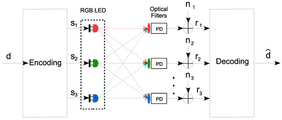
Figure 1.
Traditional color space-based VLC system model.
Our study uses CSK modulation for its complexity and sophistication as a key technique in the VLC standard IEEE 802.15.7 [5]. CSK operates by transmitting bits per symbol, where M indicates the size of the constellation. This transmission is achieved by varying the color intensities of an RGB LED. A crucial aspect of CSK is the design of the constellation’s symbols, which requires a meticulous balance between brightness and chromaticity to ensure efficient communication. The transmitted RGB optical power vector, denoted , corresponds to a specific chromaticity coordinate . This vector is calculated using the following equation, as referenced in [32]:
In this equation, , , and denote the chromaticity coordinates of red, green, and blue light sources. The transmitted signal must meet two key lighting criteria: adhering to a target color, typically white, verified via a chromaticity diagram to ensure that CSK constellation symbols match this color benchmark, and maintaining within the RGB LED’s dynamic range. The total optical power, the sum of the powers of the red (), green (), and blue () LEDs, must not exceed the limit of the dynamic range, mathematically , where is the maximum allowable average power.
In the exploration of VLC systems, particular attention is given to the receiver-side O/E conversion process. This conversion is critical in the transformation of optical signals into electrical signals, a process that is fundamentally influenced by the characteristics of the photodetector used. The analysis begins with a conventional photodetector array configuration, represented in Figure 1, which is standard in VLC systems. This configuration, while effective, presents an inherent challenge in managing the non-linear response characteristics induced by various factors such as quantum efficiency (Q.E.), wavelength (), and ambient temperature. To provide a comprehensive understanding of these dynamics, Figure 2 delves into the operational principles of a photodetector. It illustrates how incident light is converted into an electrical signal, with the photodetector’s responsivity (R) playing a central role. The figure further demonstrates the non-linear response of the photodetector to temperature variations and wavelength changes, which can significantly impact the system’s performance.
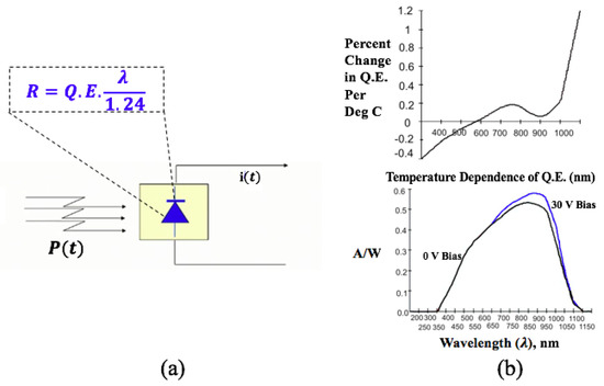
Figure 2.
Photodetector response characteristics in VLC Systems: (a) schematically represents the photodetector converting light power into an electrical current with the responsivity equation highlighted to account for material properties; (b) displays the temperature dependence of quantum efficiency (Q.E.), illustrating the percent change in responsivity per degree Celsius and the wavelength dependence of responsivity under different bias voltages.
An alternative detection method employing a single photodetector array is also introduced in Figure 3. This approach aims to simplify the system’s design, reducing both complexity and cost and facilitating better integration with IoT technologies. However, simplifying the design also accentuates the challenge of accurately managing the non-linear O/E conversion process. Therefore, it prioritizes implementation efficiency, offering substantial advantages in deployment and integration with IoT technologies, with careful consideration required for the conversion intricacies that could affect system performance.
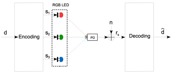
Figure 3.
Single photodetector-based VLC color space-based VLC system model.
In terms of enhancing the performance of the symbol error probability, the maximum-likelihood (ML) method is used with the photodetector array. The ML method aims to minimize the Euclidean distance between the received signal vector (as defined in (2)) and all possible transmitted signals. The optimal function of the ML detector can be formulated as follows:
where represents the estimated value of d, which is mapped to one of the signal vectors in the set , and denotes the 2-norm.
An alternative to the photodetector array to detect RGB light signals is the use of a single photodiode (SPD) [33]. This approach, illustrated in Figure 3, simplifies the receiver design by using just one photodetector and omitting any optical filters. The fundamental principle of the SPD is based on the wavelength-dependent responsivity of the photodiode. This feature allows for the mapping of received optical signals to distinct scalar values, each corresponding to the wavelengths of the individual RGB LEDs. With the SPD configuration, the received signal model, initially formulated in (2), is adapted to the following:
where represents the photodetector’s responsivity at the peak wavelengths for the red, green, and blue components. The symbol signifies the dot product operation, and the photodetector output is a combination of the influence of the channel matrix and a scalar representation of noise. Similarly to the approach in (4), the SPD receiver determines the transmitted symbol by employing an optimal detection strategy. This is expressed as follows.
where indicates the absolute value. This method allows the SPD receiver to effectively identify the transmitted symbol, optimizing detection in the VLC system.
3. CSK-Based VLC System Design Using Neural Networks
In this section, we delve into the design of our CSK-based VLC system, which utilizes an innovative autoencoder-based approach. Initially, we detail the architecture of our autoencoder model, focusing on its core components, including the crucial hidden layers that play a vital role in the system’s learning and adaptation capabilities. We elaborate on the meticulous design of the training framework, which is tailored to optimize the weights and biases within these layers, effectively minimizing the cost function for enhanced performance.
3.1. Autoencoder Design
In our study, we conceptualize the VLC system within an autoencoder framework consisting of three primary components: the encoder, the code, and the decoder. The transmitter and receiver are represented as two separate parametric neural networks, envisioned, respectively, as the encoder and decoder. These networks are jointly optimized to meet specific performance criteria, with the Additive White Gaussian Noise (AWGN) channel representing the code.
3.1.1. Hyperparameters
Our autoencoder’s efficiency is significantly influenced by the selection of optimal hyperparameters. The key parameters that we fine-tuned during the optimization process are detailed in Table 1.

Table 1.
Optimized hyperparameters for autoencoder efficiency.
3.1.2. Cost Function
Our goal is to jointly optimize the transmitter and receiver network parameters. This is achieved using the following cost function:
is defined using the categorical cross-entropy metric to measure the discrepancy between the input symbols and their predicted probabilities:
where is the true value for the m-th symbol, and is the predicted probability for the m-th symbol. The categorical cross-entropy metric () plays a pivotal role in the cost function, not only measuring the accuracy discrepancy between input values and their predicted counterparts but also implicitly favoring the maximization of the minimum Euclidean distance between constellation symbols. Well-separated symbols naturally lead to a lower cross-entropy value, which correlates with a more accurate and reliable system performance. The integration of this metric thus subtly but effectively ensures that symbols are sufficiently spaced in the constellation without necessitating an additional explicit term in the loss function for the Euclidean distance.
The second term, , incorporates the chromaticity constraint for illumination, integrating the RGB constraint in the CIE chromaticity diagram:
where CCT represents the desired color temperature and is the color temperature resulting from the RGB lights produced by the transmitter. The computation of is based on McCamy’s approximation [34]:
where , given the measured chromaticity coordinates . Lastly, the parameter controls the relative contribution of the penalty term provided in (9).
The balance within the cost function, as reflected in Equation (7), between the accuracy-focused and the chromaticity constraint , has been carefully calibrated to support robust performance while maintaining compliance with illumination requirements.
3.2. Autoencoder Simulation Framework
In this section, we outline the simulation framework used to model the VLC system using neural networks. The proposed simulation structure can be seen in Figure 4.
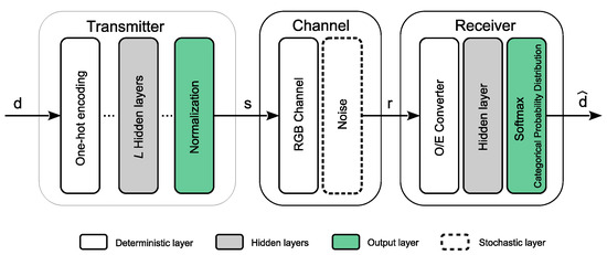
Figure 4.
Proposed end-to-end VLC structure.
3.2.1. Transmitter
The transmitter begins by mapping each training input symbol from the set and ranging from to a one-hot vector in the set . The set comprises distinct one-hot vectors, defined as:
This vector is then passed through L fully-connected hidden layers, each with M neurons, except the last layer, which has N neurons. The output from the l-th layer, where l ranges from 1 to L, is given by:
where , , and represent the weights matrix, input vector, and bias vector, respectively, with as the activation function. Notice that for , , and for , , , and . The final output from the transmitter, symbolizing the CSK constellation symbol for the i-th training symbol, is normalized to uphold power constraints:
where ∘ denotes the Hadamard product, and is the normalization vector ensuring
3.2.2. Channel
Our novel autoencoder architecture is initially analyzed using an AWGN channel for simplicity and to gain basic insights before addressing more complex scenarios. This is apt for VLC, where non-line of sight reflections are minimal, aligning with the AWGN model’s characteristics.
In the stochastic channel layer of the model, the transmitted optical signal vector is first multiplied by the identity matrix . We then introduce a noise vector , adhering to the normal distribution , to this product. Consequently, the output from the channel layer for the i-th training symbol is formulated as:
with is . It is important to note that although the noise samples for each training symbol are independent and identically distributed (i.i.d.), their specific statistics are not discernible during the training phase. This consideration is crucial for accurately modeling the stochastic nature of the channel within our autoencoder framework.
3.2.3. Receiver
The receiver’s primary function in our VLC system is to decode the channel output, , to accurately approximate the original transmitted symbol. This process begins with the output being fed through a deterministic O / E conversion layer, which is subsequently passed through the J hidden neural network layers. The output from each hidden layer, j, where j ranges from 1 to J, is formulated as:
in this expression, , , and represent the weight matrix, input vector, and bias vector for each layer, respectively. Each layer utilizes the activation function . In particular, the first layer’s input is specifically .
Following the hidden layers, the output layer uses the softmax activation function to calculate the probabilities corresponding to each predicted class. These probabilities are determined by:
where is the m-th element of the output layer. The final step in the decoding process involves determining the estimated training symbol, , by identifying the element with the highest probability:
4. System Configuration and Evaluation Criteria
Following the autoencoder design outlined in Section 3, this section elaborates on the specific configurations of our VLC system for numerical evaluation. We detail the setup processes, performance metrics, and computational complexity assessments involved, offering a framework essential for understanding the numerical results discussed in Section 5.
4.1. Setup
Our approach is designed to develop an optimal CSK-based modulation set, achieved by training the autoencoder parameters in a noise-free environment. In this approach, the model acclimates to the modulation symbols derived from the training data without the influence of noise factors. The crux of this method lies in maximizing the minimum Euclidean distance among the modulation symbols. This is in contrast to noise-aware models, which require a prior estimation of noise statistics and necessitate updates to the modulation set upon any changes in these statistics. A key advantage of our noise-free approach is the rapid training process that leads to optimal results. This efficiency is due to the fact that the goal of maximizing Euclidean distance between modulation symbols is not impacted by noise, making it a robust strategy regardless of noise conditions.
Table 2 presents the detailed structure of our proposed autoencoder for the VLC network. The transmitter consists of a one-hot mapping layer, two hidden layers, and a normalization layer, with the maximum transmitted optical power for each color channel normalized to a value of one (as specified in Section 3.2.1). Conversely, the receiver integrates two fully connected hidden layers, each containing M neurons. We employed silicon photodiodes as optical detectors to investigate the nuances of the O/E conversion response. The specifications of the light sources and optical receivers used in our VLC system are listed in Table 3. Notably, the responsivity vector is derived based on the documented response in [31], with defined wavelengths of nm, nm and nm.
Table 2.
Autoencoder structure.
Table 3.
Electric and optical parameters.
We assess the performance of the VLC system across four distinct scenarios:
- CSK-VLC-AE (baseline): This scenario serves as a baseline, employing a maximum-likelihood detector to identify data symbols in the RGB channels without considering optical-to-electrical (O/E) conversion effects. This ideal case helps establish a performance benchmark under optimal conditions.
- CSK-VLC-AE with O/E: This scenario is similar to the baseline but includes the impact of O/E conversion at the receiver, using the same ML detection method. This comparison highlights the effects of O/E conversion on system performance.
- CSK-VLC-AE with SPD: Here, we implement a system using a single-photodiode (SPD) detector, which inherently includes O/E conversion. This setup is crucial for understanding the performance trade-offs when employing a cost-effective, simplified detector configuration.
- CSK-VLC with O/E (traditional non-autoencoder system): This scenario compares our autoencoder approach with a traditional VLC system using CSK modulation and ML detection that includes O/E conversion. This comparison serves as a critical benchmark to evaluate the advantages of integrating autoencoders into VLC systems.
The network model is trained with samples on 10 epochs, using a mini-batch size of and Adam optimizer with a learning rate of . The effectiveness of these schemes is tested using data symbols, analyzing the SER outcomes. During our training phase, we used both the transmitter and receiver networks to evaluate the average SER performance. For the testing phase, we analyzed data symbols to compare SER across the three outlined schemes.
4.2. Performance Metrics
Evaluating the performance and complexity of our neural network-based VLC system is crucial. This subsection details the metrics we have selected for this evaluation, enabling a comprehensive comparison of the different schemes under study.
Symbol Error Rate: A key metric in assessing the efficiency of digital communication systems is the SER in relation to the SNR. To estimate the SER, we conducted simulations using the learned transmitter and receiver with a substantial number of symbols. We calculate the SER by comparing the ratio of erroneously received symbols to the total number of transmitted symbols, defined as:
Minimum Euclidean distance: Another critical metric is the minimum Euclidean distance between symbols in a modulation scheme. This distance is indicative of a communication system’s performance, with a larger Euclidean distance generally implying better performance. To assess this, we evaluate the minimum Euclidean distance among the signals received by our VLC receiver, calculated as:
where and are elements of the set for .
4.3. Processing Complexity
In assessing the efficiency of our proposed model, it is important to consider the processing complexity of the autoencoder architecture. To this end, the computational complexities of the individual layers are detailed in Table 4, offering a granular view of the computational demands of the model. Our analysis includes a representative complexity function for the entire architecture, formulated as , which simplifies to a complexity of . Moreover, the adoption of parallel processing, a common practice in neural network operations, can significantly mitigate these computational requirements.
Table 4.
Number of mathematical operations in the end-to-end autoencoder model.
Comparing this to conventional systems, the autoencoder stands out for its balanced computational profile. Traditional VLC systems often have fluctuating computational needs based on their detection methods. For instance, optimal ML detectors with a photodetector array can have a complexity of , while a single-photodiode detector simplifies this to .
5. Results
This section discusses the impact of O/E conversion on our CSK-modulated autoencoder VLC system. We initially trained the CSK-VLC-AE network to incorporate the autoencoder’s explicit structure and the effects of O/E conversion. The learning curves of the dataset indicated a rapid and effective acquisition of transmitter and receiver functions, with a training accuracy that quickly reached and stabilized nearly 100% after the initial epochs. The loss, combining the terms and of our methodology, showed rapid stabilization, maintaining a consistent average in the later training stages. Specifically, after the fifth epoch, the loss value leveled at around 0.42, indicating that the model had successfully converged. The Adam optimizer was particularly effective in later learning stages, even with suboptimal hyperparameters. Following a similar approach, we trained and tested two other scenarios: CSK-VLC-AE without O/E and CSK-VLC-AE with SPD. Both yielded results consistent with our initial network model.
Figure 5 illustrates the average SER performance in relation to SNR for the VLC schemes evaluated. Incorporating O/E conversion at the receiver notably degrades SER performance. Specifically, the CSK-VLC-AE scheme shows a performance drop of approximately 10 dB at an average SER of , and an additional 8 dB decrease is observed in the CSK-VLC-AE with SPD scheme. To provide a benchmark, the results of a traditional non-autoencoder VLC system, CSK-VLC with O/E, which incorporates O/E effects and utilizes a maximum-likelihood detector, are also presented (see Figure 1). Despite utilizing well-established detection methods, this traditional VLC system is consistently outperformed by the CSK-VLC-AE schemes, particularly at SNRs above 12 dB and SERs below . This highlights the autoencoder’s ability to enhance SER performance amidst the challenges posed by O/E conversion. As noise levels increase, surpassing signal levels, all schemes exhibit an uptick in error rates. However, the resilience of the CSK-VLC-AE approaches underscores their potential advantages in practical VLC system applications.
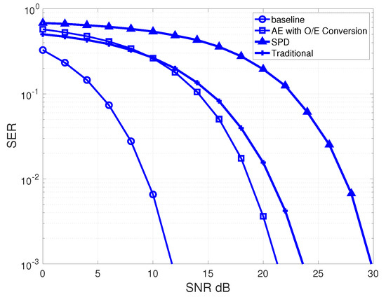
Figure 5.
SER performance results of the CSK-based autoencoder VLC system according to the baseline scheme, the cases with O/E conversion and SPD detection, and an additional curve representing a traditional VLC system employing maximum-likelihood detection for comparison.
In Figure 6, Figure 7 and Figure 8, the 4-CSK mapping constellations for the autoencoder-based schemes are displayed in the CIE 1931 color space for the respective examined configurations. The central wavelengths of RGB LEDs are indicated by circles, with the optimal color coordinates for each constellation symbol shown as squares, and the average color tonality is represented by a red cross, with an aim to reproduce the D65 color standard. Figure 6 represents the standard CSK-VLC-AE scheme, Figure 7 illustrates the CSK-VLC-AE scheme with O/E conversion, and Figure 8 shows the CSK-VLC-AE scheme with SPD. All schemes strive for D65 white tonality. Additionally, the MacAdam ellipse on the CIE 1931 xy chromaticity diagram is included to emphasize colors that are indistinguishable from the ellipse’s center to the average human eye.
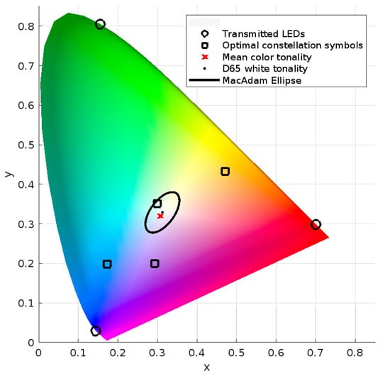
Figure 6.
Resulting optimal constellation symbols (N = 3) for scheme CSK-VLC-AE for and using D65 white tonality as target.
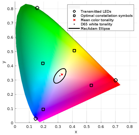
Figure 7.
Resulting optimal constellation symbols (N = 3) for scheme CSK-VLC-AE with O/E for and using D65 white tonality as target.
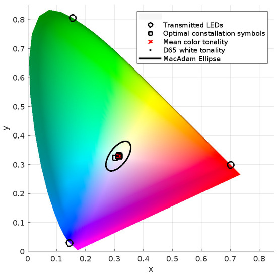
Figure 8.
Resulting optimal constellation symbols (N = 3) for scheme CSK-VLC-AE with SPD for and using D65 white tonality as target color.
Table 5 details the constellation sets for each case study, focusing on the minimum distance at the transmitter for each scheme. Evaluating the minimum distance between constellation symbols at the receiver reveals the effect of photoelectric conversion, with decreasing significantly due to this impact. The SPD-structured system further reduces this minimum Euclidean distance, as the transmitted RGB vector aligns with the sensitivity response.
Table 5.
CSK constellations learned for and K.
The Euclidean distance at the receiver plays a crucial role in error probability. Figure 9 contrasts the constellations at the receiver for the standard CSK-VLC-AE scheme with those impacted by O/E conversion and SPD scenarios. The constellation points in the O/E and SPD scenarios are noticeably closer due to photoelectric conversion, reducing their effectiveness in minimizing error probability compared to the baseline configuration.
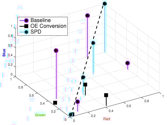
Figure 9.
Receiver constellations for standard CSK-VLC-AE (baseline) and the impact of O/E conversion and SPD, showing reduced error minimization effectiveness.
6. Conclusions
In this study, we have applied the use of an autoencoder network for the design of a CSK-based VLC system, meticulously incorporating the nuances of the O/E conversion at the receiver. This end-to-end learning approach represents a notable shift from conventional mathematical models, showcasing the potential to craft multi-colored VLC transceivers leveraging sophisticated neural network algorithms. By optimizing constellation symbols with a custom cost function that combines categorical cross-entropy with chromaticity considerations, our methodology has yielded significant performance enhancements.
A critical insight from our research is the substantial influence of O/E conversion efficiency on the minimum distance between constellation symbols, which in turn, crucially affects SER performance. Specifically, our simulations show that including the O/E conversion process leads to a performance degradation of approximately 10 dB at an SER of . However, our proposed autoencoder design mitigates this degradation, improving performance by 2 dB compared to a traditional CSK-VLC system without the autoencoder. Furthermore, our findings underline the adaptability of an autoencoder framework equipped with a single-photodiode receiver as an effective solution for creating cost-efficient and energy-saving IoT deployments. Despite observed performance dips in the single-photodiode receiver configuration due to altered constellation points, potential remedies such as the augmentation of emission power present a viable countermeasure, particularly in IoT networks where power limitations may be more flexible.
By delving into the impacts of O/E conversion and introducing a learning-driven design philosophy for VLC systems, our work furthers the integration of this technology with IoT infrastructures. This research not only deepens the theoretical understanding of VLC but also extends its practical reach, setting the stage for VLC technology to thrive in diverse real-world applications. Additionally, utilizing autoencoders paves the way for future research opportunities to investigate other processes that impact both the transmitter and receiver. Although this study primarily focuses on the optical-to-electrical conversion at the receiver, the framework developed can be expanded to address other overlooked processes that influence the overall system performance and quality. Subsequent studies will further confirm the effectiveness of autoencoders in optimizing VLC systems and overcoming a wider range of challenges. Potential future applications for this technology include smart homes and offices, healthcare facilities, public transportation systems, industrial automation, AR/VR applications, and retail environments. These applications showcase the adaptability and extensive usability of our proposed VLC system design in enhancing Internet of Things (IoT) connectivity and data transmission.
Author Contributions
Conceptualization, J.M.L.-R., J.R. (Jose Rabadan) and R.P.-J.; Methodology, J.M.L.-R., J.R. (Jose Rabadan) and J.R. (Julio Rufo); Software, J.M.L.-R., J.R. (Julio Rufo) and V.G.; Validation, J.M.L.-R. and V.G.; Formal analysis, J.M.L.-R., C.A.G. and R.P.-J.; Writing—original draft, J.M.L.-R., C.A.G. and J.R. (Jose Rabadan); Writing—review & editing, R.P.-J.; Funding acquisition, J.M.L.-R., J.R. (Jose Rabadan), J.R. (Julio Rufo) and R.P.-J. All authors have read and agreed to the published version of the manuscript.
Funding
This research was funded by the Spanish State Research Agency through grants PID2020-114561RB-I00 and TED2021-130049B-C21/22, MCIN/AEI/10.13039/501100011033, and the European Union NextGenerationEU/PRTR with grant TED2021-130049A-C22. Additional funding was provided by the María Zambrano Grant from the Universidad de Las Palmas de Gran Canaria and the State Government of San Luis Potosí in Mexico with grant FME-2021-01-03, Fideicomiso 23871.
Institutional Review Board Statement
Not applicable.
Informed Consent Statement
Not applicable.
Data Availability Statement
Data is contained within the article.
Conflicts of Interest
The authors declare no conflicts of interest.
References
- Khalighi, M.A.; Uysal, M. Survey on Free Space Optical Communication: A Communication Theory Perspective. IEEE Commun. Surv. Tutor. 2014, 16, 2231–2258. [Google Scholar] [CrossRef]
- Pathak, P.H.; Feng, X.; Hu, P.; Mohapatra, P. Visible Light Communication, Networking, and Sensing: A Survey, Potential and Challenges. IEEE Commun. Surv. Tutor. 2015, 17, 2047–2077. [Google Scholar] [CrossRef]
- Qin, Z.; Ye, H.; Li, G.Y.; Juang, B.-H.F. Deep Learning in Physical Layer Communications. IEEE Wirel. Commun. 2019, 26, 93–99. [Google Scholar] [CrossRef]
- An, Y.; Wang, S.; Zhao, L.; Ji, Z.; Ganchev, I. A Learning-Based End-to-End Wireless Communication System Utilizing a Deep Neural Network Channel Module. IEEE Access 2023, 11, 17441–17453. [Google Scholar] [CrossRef]
- IEEE Std 802.15.7-2018 (Revision of IEEE Std 802.15.7-2011); IEEE Standard for Local and Metropolitan Area Networks—-Part 15.7: Short-Range Optical Wireless Communications. IEEE: Piscataway, NJ, USA, 2019; pp. 1–407. [CrossRef]
- Das, P.; Kim, B.-Y.; Park, Y.; Kim, K.-D. A New Color Space Based Constellation Diagram and Modulation Scheme for Color Independent VLC. Adv. Electr. Comput. Eng. 2012, 12, 11–18. [Google Scholar] [CrossRef]
- Drost, R.J.; Sadler, B.M. Constellation Design for Color-Shift Keying Using Billiards Algorithms. In Proceedings of the 2010 IEEE Globecom Workshops, Miami, FL, USA, 6 December 2010; pp. 980–984. [Google Scholar] [CrossRef]
- Monteiro, E.; Hranilovic, S. Design and Implementation of Color-Shift Keying for Visible Light Communications. J. Light. Technol. 2014, 32, 2053–2060. [Google Scholar] [CrossRef]
- Monteiro, E.; Hranilovic, S. Constellation Design for Color-Shift Keying Using Interior Point Methods. In Proceedings of the 2012 IEEE Globecom Workshops, Anaheim, CA, USA, 3–7 December 2012; pp. 1224–1228. [Google Scholar] [CrossRef]
- Liang, X.; Yuan, M.; Wang, J.; Ding, Z.; Jiang, M.; Zhao, C. Constellation Design Enhancement for Color-Shift Keying Modulation of Quadrichromatic LEDs in Visible Light Communications. J. Light. Technol. 2017, 35, 3650–3663. [Google Scholar] [CrossRef]
- IEEE 802.15.7-2011 and IEEE802.15.7r1, “IEEE 802.15 WPANTM”. Available online: https://www.ieee802.org/15/pub/IEEE%20802_15%20WPAN%2015_7%20Revision1%20Task%20Group.htm (accessed on 9 November 2022).
- Koonen, T. Indoor Optical Wireless Systems: Technology, Trends, and Applications. J. Light. Technol. 2018, 36, 1459–1467. [Google Scholar] [CrossRef]
- Matheus, L.E.M.; Vieira, A.B.; Vieira, L.F.M.; Vieira, M.A.M.; Gnawali, O. Visible Light Communication: Concepts, Applications and Challenges. IEEE Commun. Surv. Tutor. 2019, 21, 3204–3237. [Google Scholar] [CrossRef]
- Căilean, A.-M.; Dimian, M. Current Challenges for Visible Light Communications Usage in Vehicle Applications: A Survey. IEEE Commun. Surv. Tutor. 2017, 19, 2681–2703. [Google Scholar] [CrossRef]
- Sklar, B.; Harris, F. Digital Communications: Fundamentals and Applications, 3rd ed.; Pearson: London, UK, 2020. [Google Scholar]
- Rappaport, T.S. Wireless Communications: Principles and Practice, 2nd ed.; Prentice-Hall: Upper Saddle River, NJ, USA, 2002. [Google Scholar]
- Djordjevic, I.B. Advanced Optical and Wireless Communications Systems; Springer: Cham, Switzerland, 2018. [Google Scholar]
- Gagliardi, R.M.; Karp, S. Optical Communications, 2nd ed.; Wiley: New York, NY, USA, 1995. [Google Scholar]
- Li, Z.; Shi, J.; Zhao, Y.; Li, G.; Chen, J.; Zhang, J.; Chi, N. Deep Learning Based End-to-End Visible Light Communication with an In-Band Channel Modeling Strategy. Opt. Express 2022, 30, 28905–28921. [Google Scholar] [CrossRef] [PubMed]
- O’Shea, T.; Hoydis, J. An Introduction to Deep Learning for the Physical Layer. IEEE Trans. Cogn. Commun. Netw. 2017, 3, 563–575. [Google Scholar] [CrossRef]
- Chi, N.; Jia, J.; Hu, F.; Zhao, Y.; Zou, P. Challenges and Prospects of Machine Learning in Visible Light Communication. J. Commun. Inf. Netw. 2020, 5, 302–309. [Google Scholar] [CrossRef]
- Lee, H.; Lee, I.; Lee, S.H. Deep Learning Based Transceiver Design for Multi-Colored VLC Systems. Opt. Express 2018, 26, 6222–6238. [Google Scholar] [CrossRef] [PubMed]
- Pepe, A.; Wei, Z.; Fu, H.Y. Heuristic, Machine Learning Approach to 8-CSK Decision Regions in RGB-LED Visible Light Communication. OSA Contin. 2020, 3, 473–482. [Google Scholar] [CrossRef]
- Zhang, D.-F.; Yu, H.-Y.; Zhu, Y.-J.; Zhu, Z.-R. A Transceiver Design Based on an Autoencoder Network for Multi-Color VLC Systems. IEEE Photonics J. 2020, 12, 7902716. [Google Scholar] [CrossRef]
- Zou, C.; Yang, F. Dimming-Aware Deep Learning Approach for OOK-Based Visible Light Communication. J. Light. Technol. 2020, 38, 5733–5742. [Google Scholar] [CrossRef]
- Ulkar, M.G.; Baykas, T.; Pusane, A.E. VLCnet: Deep Learning Based End-to-End Visible Light Communication System. J. Light. Technol. 2020, 38, 5937–5948. [Google Scholar] [CrossRef]
- Shrivastava, S.; Chen, B.; Chen, C.; Wang, H.; Dai, M. Deep Q-Network Learning Based Downlink Resource Allocation for Hybrid RF/VLC Systems. IEEE Access 2020, 8, 149412–149434. [Google Scholar] [CrossRef]
- Mitra, R.; Bhatia, V. Chebyshev Polynomial-Based Adaptive Predistorter for Nonlinear LED Compensation in VLC. IEEE Photonics Technol. Lett. 2016, 28, 1053–1056. [Google Scholar] [CrossRef]
- Laakso, M.; Dowhuszko, A.A.; Wichman, R. Predistortion of OFDM Signals for VLC Systems Using Phosphor-Converted LEDs. In Proceedings of the 2022 IEEE 23rd International Workshop on Signal Processing Advances in Wireless Communication (SPAWC), Oulu, Finland, 4–6 July 2022; pp. 1–5. [Google Scholar] [CrossRef]
- Lizarraga, E.M.; Wayar, J.; Linares, M.F.; Dowhuszko, A.A. Effects of LED Non-linear Response and Waveform Settings on Multi-Cell VLC System Deployments. In Proceedings of the 2021 IEEE Latin-American Conference on Communications (LATINCOM), Santo Domingo, Dominican Republic, 17–19 November 2021; pp. 1–5. [Google Scholar] [CrossRef]
- Hamamatsu. Si PIN Photodiodes (S1223 Series). Available online: https://www.hamamatsu.com/eu/en/product/optical-sensors/photodiodes/si-photodiodes/S1223-01.html (accessed on 1 December 2023).
- Wyszecki, G.; Stiles, W.S. Color Science; Wiley: New York, NY, USA, 1982; Volume 8. [Google Scholar]
- Luna-Rivera, J.M.; Suarez-Rodriguez, C.; Guerra, V.; Perez-Jimenez, R.; Rabadan, J.; Rufo, J. Low-Complexity CSK-based Visible Light Communications System. IET Optoelectron. 2015, 9, 191–198. [Google Scholar] [CrossRef]
- McCamy, C.S. Correlated Color Temperature as an Explicit Function of Chromaticity Coordinates. Color Res. Appl. 1992, 17, 142–144. [Google Scholar] [CrossRef]
Disclaimer/Publisher’s Note: The statements, opinions and data contained in all publications are solely those of the individual author(s) and contributor(s) and not of MDPI and/or the editor(s). MDPI and/or the editor(s) disclaim responsibility for any injury to people or property resulting from any ideas, methods, instructions or products referred to in the content. |
© 2024 by the authors. Licensee MDPI, Basel, Switzerland. This article is an open access article distributed under the terms and conditions of the Creative Commons Attribution (CC BY) license (https://creativecommons.org/licenses/by/4.0/).