Article

Single Trench Fiber-Enabled High-Power Fiber Laser

1
Test Center, National University of Defense Technology, Xi’an 710106, China
2
College of Advanced Interdisciplinary Studies, National University of Defense Technology, Changsha 410073, China
3
Nanhu Laser Laboratory, National University of Defense Technology, Changsha 410073, China
*
Authors to whom correspondence should be addressed.
These authors contributed equally to this work.
Photonics 2024, 11(7), 615; https://doi.org/10.3390/photonics11070615
Submission received: 10 June 2024 / Revised: 25 June 2024 / Accepted: 27 June 2024 / Published: 28 June 2024
(This article belongs to the Special Issue Research on Rare-Earth-Doped Fiber Lasers)

Abstract

:
As a novel design of large-mode-area fiber, the single trench fiber (STF) providing high higher-order-mode suppression with a large mode area for the fundamental mode shows potential for high-power and high-brightness applications. However, the output power of STFs has remained relatively low over the past decade. In this paper, we first conducted a design process for STFs and determined the optimal ratio of the fiber structural parameters. Following this ratio, we fabricated an ytterbium-doped STF and demonstrated an all-fiberized fiber amplifier. The system achieved an output power of 2.5 kW with an M2 factor of 1.396. To the best of our knowledge, the power of the STF in this study is approximately three times higher than the previous single-mode power record.

1. Introduction

Conventional rare-earth-doped fibers feature a core with a higher refractive index (RI) and a cladding with a lower RI, ensuring guided light propagation through total internal reflection [1]. Over recent decades, in pursuit of enhanced fiber functionality [2,3], researchers have proposed various innovative designs featuring more intricate RI distributions, including multi-core [4,5], multi-layer [6], and micro-structured [7,8,9,10] fibers. These innovative fiber designs, alongside conventional fibers, have garnered significant attention in applications such as communication [11], sensing [12,13], imaging [14], and high-power lasers [15,16,17].
The single trench fiber (STF) [18,19] stands out as a typical multi-layer [6] design among the aforementioned innovative concepts, whose RI profile is depicted in Figure 1. In the STF configuration, the core is encircled by a trench layer with a low RI and a ring layer with a high RI. Previous studies have demonstrated that this arrangement not only enables a large mode area [20] but also effectively suppresses higher-order mode (HOM) [21,22]. Consequently, the rare-earth-doped STF is perceived as a promising active fiber for high-power applications.
However, the output power of the rare-earth-doped STFs has stayed at a comparatively low level over the past decade. The pioneering work on STFs dates back to 2014 when D. Jain and his colleagues first demonstrated an ytterbium-doped STF with a core diameter of 40 μm [18]. They successfully constructed a fiber laser cavity operating at the 10 W level using this STF. In 2015, the same research group utilized an STF to develop a picosecond Master Oscillator Power Amplifier (MOPA). The average output power of this MOPA was increased to 52 W [23]. Fast forward three years later, due to the introduction of an all-fiber structure, our group achieved an output power of 807 W based on an ytterbium-doped STF [24]. It is worth noting that the beam propagation factor (M2) of the output laser in the above studies is consistently less than 1.5, indicating that all laser outputs are single-mode, thanks to the high HOM suppression of the STF. In 2022, although we achieved a 1.5 kW laser output through a homemade STF [25], the corresponding M2 was measured as 1.92. The measured beam propagation factor indicates multimode operation, which can be attributed to the non-optimal RI distribution of the fabricated STF. To summarize the previous studies, the single-mode output power of STF remains below 1 kW.
In this study, we have scaled the single-mode output power of the STF to above 2 kW based on a homemade ytterbium-doped STF. Compared with our previous work [24,25], design optimizations have been made to the fiber parameters, alongside improvements in fiber fabricating techniques. Thanks to these improvements, the maximum output power of the STF-based single-mode laser reaches 2.5 kW. To our knowledge, this marks the highest output power ever achieved by any laser system utilizing STFs as the active fibers. Moving forward, Section 2 will present the fiber design process and fabrication results. Section 3 will detail the experimental setup, while Section 4 will encompass both the experimental results and discussions.

2. Fiber Design and Fabrication
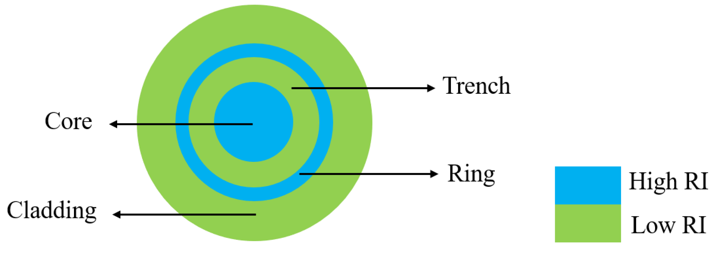
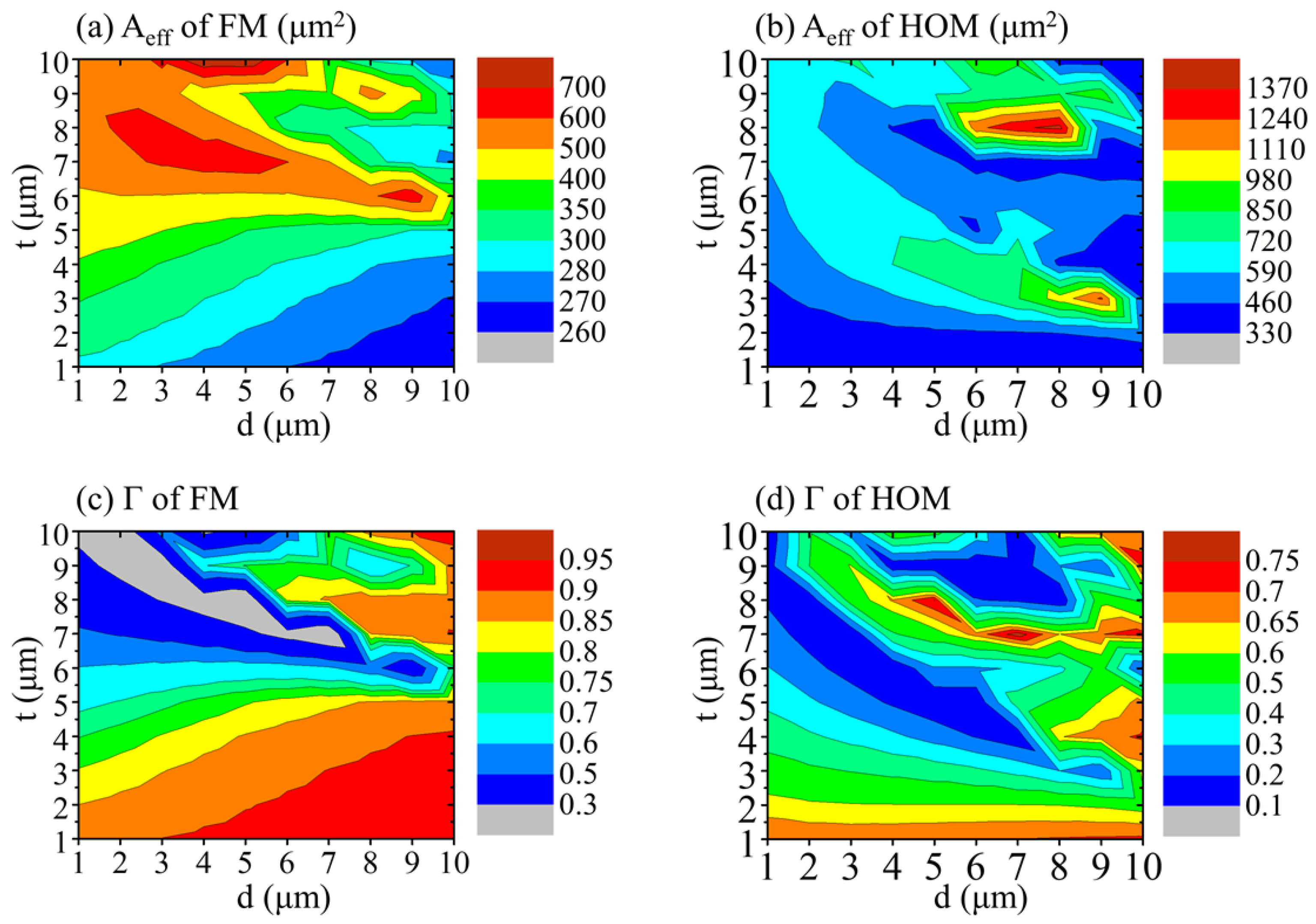
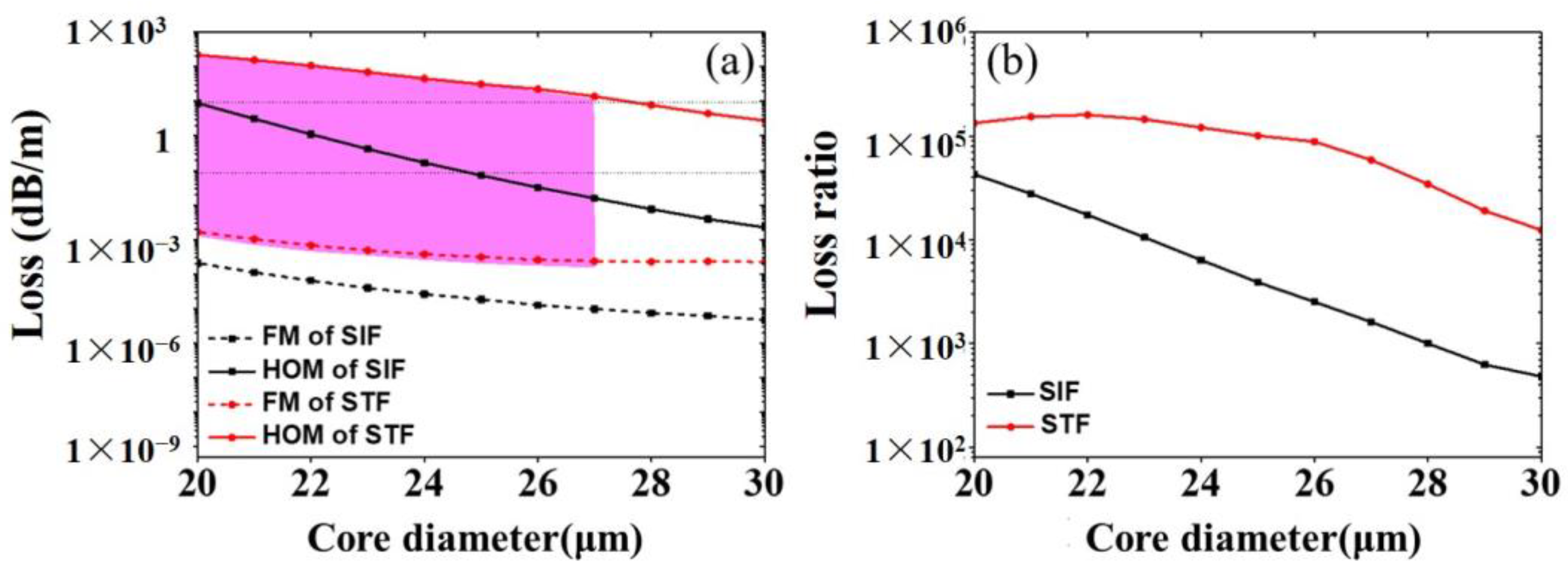
2.1. Fiber Design

The optimized design of an STF is important for its effective application in high-power fiber lasers. Here, we outline key design principles essential for optimizing high-power performance:
(1) Bending loss considerations. Generally, the bending loss of higher-order modes (HOMs) is expected to be sufficiently high, while the loss of the fundamental mode (FM) is anticipated to be sufficiently low to ensure effective single-mode (ESM) output. A criterion for achieving this is when the FM has a loss lower than 0.1 dB/m and the HOMs have losses greater than 10 dB/m, as proposed in [26]. In this study, the term HOM specifically denotes the mode characterized by the lowest bending loss among all HOMs.
(2) Large mode area [27] of fundamental mode (FM). This will help mitigate nonlinear effects such as Stimulated Raman Scattering (SRS) [28] and Stimulated Brillouin Scattering (SBS) [29] in the power amplification process.
(3) Proper overlap factor [30]. This factor characterizes the overlap between the mode field distribution and the doping region. A higher overlap factor indicates a more significant gain of the target mode to some extent. Consequently, a smaller overlap factor for the HOM and a larger one for the FM aid in suppressing the gain of the HOM in fibers.
To design an STF, let us assume initial values including a core diameter of 20 μm, a numerical aperture (NA) of 0.06, an operating wavelength of 1.08 μm, and a bending radius of 7 cm. Then, we investigate variations in both the trench thickness (d) and ring layer thickness (t) ranging from 1 to 10 μm.
Employing the finite element method (FEM), we construct a model of the STF to analyze bending loss, mode field area, and overlap factor of both the FM and HOM under different layer thicknesses. Concretely, when the STF is bent, its RI profile nbent can be calculated through the conformal mapping technique [24]
n b e n t 2 ( r , φ ) = n 2 ( r ) ( 1 + 2 r ρ R cos φ ) ,
where n represents the RI profile of the straight STF, R denotes the bending radius, and ρ is fixed at 1.25 to account for the correction factor of the elastic-optic effect. The bending loss of the FM and the HOM can be calculated based on the propagation constant β provided by FEM modeling:
α ( dB / m ) = 20 ln 10 I m ( β ) 8.686 I m ( β )
As for the mode field area Aeff, it can be expressed as
A e f f = ( 0 2 π 0 r clad | E ( r , φ ) | 2 r d r d φ ) 2 0 2 π 0 r clad | E ( r , φ ) | 4 r d r d φ ,
where rclad denotes the radius of the fiber cladding, and E represents the electric field of the FM or the HOM.
The overlap factor Γ can be calculated by
Γ = 0 2 π 0 r doped | E ( r , φ ) | 2 r d r d φ 0 2 π 0 r clad | E ( r , φ ) | 2 r d r d φ
where rdoped represents the radius of the doped region.
Figure 2 illustrates the variation in bending loss for both the FM and HOM under different trench thicknesses (d) and ring thicknesses (t) at a bending radius of 7 cm. Focusing on the bending loss of the FM shown in Figure 2a, it is apparent that when d is below 3 μm, the loss remains below 0.05 dB/m across different t values. Additionally, when t is below 4 μm, the FM loss remains under 0.01 dB/m across various d values. Moving on to the examination of the HOM bending loss depicted in Figure 2b, in regions where d is below 3 μm, it is observed that the bending loss of the HOM decreases with increasing t values, consistently remaining below 10 dB/m. Therefore, achieving the ESM condition is challenging when d is below 3 μm. Conversely, exploring regions where t is below 4 μm, it is noted that when d ranges from 9 to 10 μm and t is 3 μm, the HOM experiences its highest loss, potentially exceeding 150 dB/m in bending loss. After observing bending loss variations for the FM and HOM, initial parameters for STF design can be proposed: a trench thickness of 9–10 μm and a ring thickness of 3 μm.
The variations in mode field area (Aeff) and overlap factor (Γ) for the STF are depicted in Figure 3. As shown in Figure 3a,c, achieving a simultaneously large Aeff and high Γ of the FM presents challenges. For the design parameters of a 9–10 μm trench thickness and a 3 μm ring thickness, the Aeff of the FM is relatively smaller compared to other design parameters, but the Γ of the FM is higher. In Figure 3b,d, the parameter combination of a 9 μm trench thickness and a 3 μm ring thickness exhibits a smaller Γ of the HOM than the combination of a 10 μm trench thickness and a 3 μm ring thickness.
Based on the variations in bending loss, mode field area, and overlap factor, it can be inferred that for an STF with a core diameter of 20 μm, the optimal design parameters include a trench thickness of 9 μm and a ring thickness of 3 μm. The optimized ratio of the core radius to trench thickness to ring thickness is 10:9:3.
The above analysis assumes a 20 μm core diameter for the STF. In high-power fiber lasers, larger core diameters are also commonly employed. Therefore, it is necessary to figure out the optimal fiber parameters for STFs with larger core diameters. We adopted a similar analyzing methodology to investigate STFs with core diameters of 22 μm, 25 μm and 30 μm. The results show that the optimized design parameters maintained a consistent ratio of the core radius to trench thickness to ring thickness of approximately 10:9:3, consistent with the case when the core diameter is 20 μm.
The bending loss for the optimized STF (ratio of core radius to trench thickness to ring thickness is 10:9:3) and the common step-index fiber (SIF) under different core diameters are compared in Figure 4a. The SIF shares all parameters with the STF, except for the trench and ring layers. It is found that the STFs achieved the ESM conditions within core diameter ranges of 20–27 μm, while the ordinary SIF only met the ESM conditions at a core diameter of 20 μm. Additionally, Figure 4b depicts the loss ratio of the HOM to the FM for STFs and SIFs. The loss ratio in STFs is significantly higher than that of ordinary SIFs, indicating a superior HOM suppression capability across different core diameters.
Among core diameters ranging from 20 μm to 30 μm, we choose 25 μm as the verifying parameter to fabricate the STF and carry out high-power experiments.

2.2. Fiber Fabrication

By utilizing the Modified Chemical Vapor Deposition (MCVD) technique [31], we fabricate an ytterbium-doped STF. This homemade fiber features a core diameter of 25 μm, an inner cladding diameter of 400 μm, and respective thicknesses of 12.3 μm for the trench layer and 4.3 μm for the ring layer. The ratio of the core radius to trench thickness to ring layer thickness for this fiber is 10:9.9:3.4, closely resembling the optimal designs. Figure 5 illustrates the measured and fitted RI profiles, represented by the black and red curves, respectively. The insets in Figure 5 show microscopic images of the fiber endface and its central enlargement, clearly revealing the trench and ring layers. Notably, the core presents a relatively uniform RI, with a fitted value of 1.45126, while both the trench and ring layers exhibit an RI of 1.4501 and 1.45126, respectively. The absorption coefficients at 915 nm, 976 nm, and 1018 nm are 0.473 dB/m, 1.209 dB/m, and 0.196 dB/m, respectively.

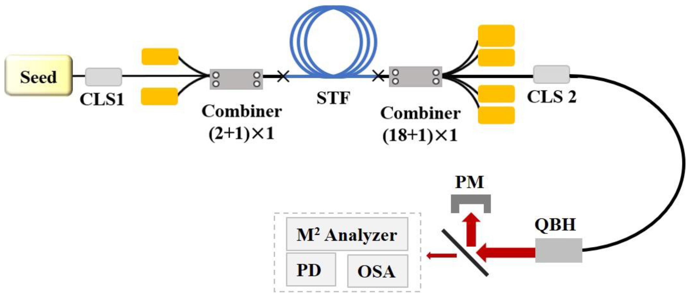
3. Experimental Setup

The experimental setup for the STF-based fiber amplifier is depicted in Figure 6. The seed is a single-mode laser emitting at a center wavelength of 1050 nm with an output power of 140 W. The seed light traverses through the cladding light stripper (CLS 1) and the (2 + 1) × 1 side pump combiner before being introduced into the main amplifier stage. The backward pumping structure incorporates a laser diode (LD) pump source with an unsteady wavelength of 976 nm, injected into the amplifier via an (18 + 1) × 1 end-pump combiner. In the initial experiment, a 23 m long STF is coiled on the water-cooling plate with guiding grooves shaped like a figure “8”, resulting in a bending radius of 8.0~9.8 cm. The bending radius of the fiber input end is 8.0 cm, while the output end is 8.4 cm. Following amplification, the laser passes through the cladding light stripper (CLS 2) before being emitted into free space via the quartz block head (QBH). Afterwards, the output laser undergoes testing using a system that includes a power meter (PM), an M2 analyzer, a photodetector (PD), and an optical spectrum analyzer (OSA). The laser reflected by the high-reflection mirror is directed into the PM for power measurements. Due to the limited power handling capacity of the PD and OSA, scattered light from the laser transmitted through the high-reflection mirror is directed into either the PD for time-domain measurements or the OSA for spectral measurements. The laser that passes through the high-reflection mirror ultimately enters the M2 analyzer for beam quality measurement.

4. Experimental Results and Discussion

The correlation between the output power of the fiber amplifier and the pump power is illustrated in Figure 7. As the backward pump power increases, the optical-to-optical efficiency (O-O efficiency) fluctuates within the range from 65% to 85%. Specifically, as the backward pump power scales up from 294 W to 3148 W, the output power experiences a variation from 340 W to 2.7 kW.
However, upon further enhancement of the pump power, fluctuations of the order of kHz were observed in the time-domain signals of the output laser, indicating the threshold of transverse mode instability (TMI) [32,33,34]. Consequently, it was decided not to proceed with additional pump power increments.
The output spectra of this fiber amplifier under various output powers are depicted in Figure 8. Notably, owing to the backward pumping configuration, no residual pump light is observed in the output laser. With increasing output power, the center wavelength of the spectrum consistently remains at 1050 nm, and the spectral width experiences a slight augmentation. When the output power reaches 2.5 kW, an SRS peak can be observed.
The measured M2 factors and corresponding beam waist spots at various output powers are illustrated in Figure 9. Initially, the M2 factors of the seed light in the x and y directions are determined to be 1.318 and 1.265, respectively, resulting in an equivalent M2 factor of 1.291. As the power increases, there is a general tendency for the M2 factor to slightly increase. When the output power reaches 2530 W, the M2 factors of the output laser in the x and y directions reach at 1.455 and 1.340, respectively, resulting in an equivalent M2 factor of only 1.396. This observed change in the M2 factor with output power indicates that the homemade STF demonstrates a commendable ability to maintain good beam quality.
The above results show the variation in the power, spectra, and M2 of the STF under the initial conditions described in Section 3. The output power of the STF is restricted by the TMI effects. It is noteworthy that, due to appearance of Raman signals at the highest power of backward pumping and the fact that forward pumping will suffer significant Raman effects for the seed at 1050 nm (denote this seed laser as seed #1), bidirectional pumping experiments were not conducted.
To explore the influence of other experimental conditions (fiber bending radius, laser seed wavelength, pumping conditions, etc.) on this STF, we further carried out a series of experiments, and the results are listed in Table 1.
As indicated in Table 1, when adopting seed #2 with a central wavelength of 1080 nm for power amplification experiments, a 2.5 kW single-mode output (M2 equals 1.48) can also be achieved through bidirectional pumping. However, when scaling the power to 3 kW, the M2 factor degrades to 1.60, indicating a multimode output.
Then, seed #2 is replaced with seed #3, which offers better output beam quality. It is observed that for the amplification of seed #3, M2 remains relatively smaller than in the case of seed #2 when the output power is below 2.5 kW. However, as the output power exceeds 2.5 kW, the beam quality deteriorates. At 3 kW, the M2 factor degrades to 1.61, which is similar to the case of seed #2.
To investigate the impact of bending conditions on beam quality and the TMI threshold, the bending radius of the fiber output end is reduced from 8.4 cm to 7.0 cm. In this case, the TMI threshold increases by approximately 130 W and 220 W for backward and bidirectional pumping, respectively. This implies that changing the bending conditions contributes to the enhancement of the TMI threshold. The M2 factor at a 1.5 kW output power remains consistent with the previous bending condition. However, at 3 kW, the M2 factor degrades to 1.67, noticeably larger than the M2 value in the previous case. The degradation of M2 indicates that changing the bending conditions does not help enhance the single-mode output power of the STF.
When comparing the high-power results of the different experimental conditions listed in Table 1, an interesting phenomenon of beam quality variation can be observed. Despite variations in the beam quality of the seed or the bending of the fiber, once the output power exceeds 2.5 kW, the laser output from the STF rapidly degrades into a multimode state (M2 > 1.5). One possible reason is that as the power increases, phase-shifted refractive index grating [34,35] develops to couple the power from the FM to the HOM. Future research endeavors can delve into investigating the mechanism behind this phenomenon and exploring strategies to overcome it.
The aforementioned findings illustrate that this homemade STF can yield a single-mode laser output of 2.5 kW. Notably, this output power represents a significant improvement compared to previously reported results of STFs, with the single-mode output power increasing by a factor of three. Moreover, our results also suggest that further research is necessary to mitigate the degradation of the M2 factor as the output power of the STF exceeds 2.5 kW.

5. Conclusions

In conclusion, this study presents the design and application of STFs in high-power fiber lasers. By adhering to key design principles for high-power applications, we obtained optimized STF parameters, maintaining a consistent ratio of the core radius to trench thickness to ring thickness of 10:9:3. Then, we fabricated an ytterbium-doped STF with a core diameter of 25 μm. Utilizing this homemade STF, we obtained a single-mode laser output of 2.5 kW, representing a significant improvement compared to previously reported results. Further efforts can be directed toward addressing beam quality degradation as the power increases to achieve higher single-mode output power for STFs.

Author Contributions

Conceptualization, Y.A. and L.H.; methodology, F.L., H.Y., X.C., Z.Y. and Z.P.; validation, Y.A., F.L., B.Y. and P.W.; formal analysis, Y.A., F.L., B.Y. and L.H.; writing—original draft preparation, Y.A. and F.L.; writing—review and editing, L.H. and M.J.; supervision, Z.J. and P.Z. All authors have read and agreed to the published version of the manuscript.

Funding

This study was funded by the National Natural Science Foundation of China (61805280, 62305385).

Institutional Review Board Statement

Not applicable.

Informed Consent Statement

Not applicable.

Data Availability Statement

The data presented in this study are available from the corresponding authors upon reasonable request.

Conflicts of Interest

The authors declare no conflicts of interest.

References

  1. Bai, H.; Li, S.; Barreiros, J.; Tu, Y.; Pollock, C.R.; Shepherd, R.F. Stretchable distributed fiber-optic sensors. Science 2020, 370, 848–852. [Google Scholar] [CrossRef] [PubMed]
  2. Abouraddy, A.F.; Bayindir, M.; Benoit, G.; Hart, S.D.; Kuriki, K.; Orf, N.; Shapira, O.; Sorin, F.; Temelkuran, B.; Fink, Y. Towards multimaterial multifunctional fibres that see, hear, sense and communicate. Nat. Mater. 2007, 6, 336–347. [Google Scholar] [CrossRef]
  3. Xiong, Y.F.; Xu, F. Multifunctional integration on optical fiber tips: Challenges and opportunities. Adv. Photonics 2020, 2, 064001. [Google Scholar] [CrossRef]
  4. Saitoh, K.; Matsuo, S. Multicore Fiber Technology. J. Light. Technol. 2016, 34, 55–66. [Google Scholar] [CrossRef]
  5. Anashkina, E.A.; Andrianov, A.V.; Litvak, A.G. Numerical Simulation of High-Power Optical Amplifiers at 2.3 µm Based on a Special Multicore Fiber. Photonics 2023, 10, 711. [Google Scholar] [CrossRef]
  6. Garcia, S.; Gasulla, I. Universal characteristic equation for multi-layer optical fibers. IEEE J. Sel. Top. Quantum. 2020, 26, 1–11. [Google Scholar] [CrossRef]
  7. Gao, S.F.; Wang, Y.Y.; Ding, W.; Jiang, D.L.; Gu, S.; Zhang, X.; Wang, P. Hollow-core conjoined-tube negative-curvature fibre with ultralow loss. Nat. Commun. 2018, 9, 2828. [Google Scholar] [CrossRef]
  8. Russell, P. Photonic crystal fibers. Science 2003, 299, 358–362. [Google Scholar] [CrossRef]
  9. Skibina, J.S.; Iliew, R.; Bethge, J.; Bock, M.; Fischer, D.; Beloglasov, V.I.; Wedell, R.; Steinmeyer, G. A chirped photonic-crystal fibre. Nat. Photonics 2008, 2, 679–683. [Google Scholar] [CrossRef]
  10. Tang, Z.W.; Zheng, Z.H.; Li, B.Y.; Wei, Z.Y.; Sun, J.H. Applications of Microstructured Optical Fibers in Ultrafast Optics: A Review. Photonics 2024, 11, 151. [Google Scholar] [CrossRef]
  11. Richardson, D.J.; Fini, J.M.; Nelson, L.E. Space-division multiplexing in optical fibres. Nat. Photonics 2013, 7, 354–362. [Google Scholar] [CrossRef]
  12. Chen, J.H.; Li, D.R.; Xu, F. Optical Microfiber Sensors: Sensing Mechanisms, and Recent Advances. J. Light. Technol. 2019, 37, 2577–2589. [Google Scholar] [CrossRef]
  13. Liu, Z.; Zhang, Z.F.; Tam, H.-Y.; Tao, X. Multifunctional Smart Optical Fibers: Materials, Fabrication, and Sensing Applications. Photonics 2019, 6, 48. [Google Scholar] [CrossRef]
  14. Stellinga, D.; Phillips, D.B.; Mekhail, S.P.; Selyem, A.; Turtaev, S.; Cizmar, T.; Padgett, M.J. Time-of-flight 3D imaging through multimode optical fibers. Science 2021, 374, 1395–1399. [Google Scholar] [CrossRef] [PubMed]
  15. Nilsson, J.; Payne, D.N. High-power fiber lasers. Science 2011, 332, 921–922. [Google Scholar] [CrossRef] [PubMed]
  16. Zervas, M.N.; Codemard, C.A. High Power Fiber Lasers: A Review. IEEE J. Sel. Top. Quantum. 2014, 20, 219–241. [Google Scholar] [CrossRef]
  17. Jauregui, C.; Limpert, J.; Tünnermann, A. High-power fibre lasers. Nat. Photonics 2013, 7, 861–867. [Google Scholar] [CrossRef]
  18. Jain, D.; Jung, Y.; Nunezvelazquez, M.; Sahu, J.K. Extending single mode performance of all-solid large-mode-area single trench fiber. Opt. Express 2014, 22, 31078–31091. [Google Scholar] [CrossRef] [PubMed]
  19. Jain, D.; Alam, S.; Jung, Y.; Barua, P.; Velazquez, M.N.; Sahu, J.K. Highly efficient Yb-free Er-La-Al doped ultra-low NA large mode area single-trench fiber laser. Opt. Express 2015, 23, 28282–28287. [Google Scholar] [CrossRef]
  20. Jain, D.; Sahu, J.K. Large mode area single trench fiber for 2 μm operation. J. Light. Technol. 2016, 34, 3412–3417. [Google Scholar] [CrossRef]
  21. An, Y.; Yang, H.; Chen, X.; Huang, L.J.; Yan, Z.P.; Pan, Z.Y.; Wang, Z.F.; Jiang, Z.F.; Zhou, P. Seeing the strong suppression of higher order modes in single trench fiber using the S2 technique. Opt. Lett. 2023, 48, 61–64. [Google Scholar] [CrossRef] [PubMed]
  22. Fini, J.M. Design of solid and microstructure fibers for suppression of higher-order modes. Opt. Express 2005, 13, 3477–3490. [Google Scholar] [CrossRef] [PubMed]
  23. Jain, D.; Alam, S.; Codemard, C.; Jung, Y.; Zervas, M.N.; Sahu, J.K. High power, compact, picosecond MOPA based on single trench fiber with single polarized diffraction-limited output. Opt. Lett. 2015, 40, 4150–4153. [Google Scholar] [CrossRef] [PubMed]
  24. Huang, L.J.; Yao, T.F.; Yang, B.H.; Leng, J.Y.; Zhou, P.; Pan, Z.Y.; Gu, S.Y.; Cheng, X.A. Modified single trench fiber with effective single-mode operation for high-power application. IEEE J. Sel. Top. Quantum. 2018, 24, 0901409. [Google Scholar] [CrossRef]
  25. An, Y.; Chen, Y.S.; Xiao, H.; Wu, H.S.; Chen, X.; Yang, H.; Yan, Z.P.; Huang, L.J.; Leng, J.Y.; Pan, Z.Y.; et al. 1.5 kW fiber amplifier employing home-made large-mode-area single trench fiber. In Proceedings of the Eighth Symposium on Novel Photoelectronic Detection Technology and Applications, Kunming, China, 7–9 December 2021; p. 121694R. [Google Scholar]
  26. Li, M.J.; Chen, X.; Liu, A.P.; Gray, S.; Wang, J.; Walton, D.T.; Zenteno, L.A. Limit of effective area for single-mode operation in step-index large mode area laser fibers. J. Light. Technol. 2009, 27, 3010–3016. [Google Scholar] [CrossRef]
  27. Xing, Z.; Wang, X.; Lou, S.Q.; Zhang, W.; Tang, Z.J.; Yan, S.B. Bend resistant large mode area fiber with step-index core and single trench. Opt. Fiber Technol. 2019, 48, 15–21. [Google Scholar] [CrossRef]
  28. Kim, J.; Dupriez, P.; Codemard, C.; Nilsson, J.; Sahu, J.K. Suppression of stimulated Raman scattering in a high power Yb-doped fiber amplifier using a W-type core with fundamental mode cut-off. Opt. Express 2006, 14, 5103–5113. [Google Scholar] [CrossRef] [PubMed]
  29. Kobyakov, A.; Sauer, M.; Chowdhury, D. Stimulated brillouin scattering in optical fibers. Adv. Opt. Photonics 2010, 2, 1–59. [Google Scholar] [CrossRef]
  30. Stutzki, F.; Jansen, F.; Otto, H.-J.; Jauregui, C.; Limpert, J.; Tünnermann, A. Designing advanced very-large-mode-area fibers for power scaling of fiber-laser systems. Optica 2014, 1, 233–242. [Google Scholar] [CrossRef]
  31. Bufetova, G.; Kosolapov, A.; Yashkov, M.; Umnikov, A.; Velmiskin, V.; Tsvetkov, V.; Bufetov, I. Extra-High Pressure in the Core of Silica-Based Optical Fiber Preforms during the Manufacturing Process. Photonics 2023, 10, 335. [Google Scholar] [CrossRef]
  32. Tao, R.M.; Ma, P.F.; Wang, X.L.; Zhou, P.; Liu, Z.J. 1.3 kW monolithic linearly polarized single-mode master oscillator power amplifier and strategies for mitigating mode instabilities. Photonics Res. 2015, 3, 86–93. [Google Scholar] [CrossRef]
  33. Tao, R.M.; Wang, X.L.; Zhou, P. Comprehensive theoretical study of mode instability in high-power fiber lasers by employing a universal model and its implications. IEEE J. Sel. Top. Quantum. 2018, 24, 1–19. [Google Scholar] [CrossRef]
  34. Jauregui, C.; Stihler, C.; Limpert, J. Transverse mode instability. Adv. Opt. Photonics 2020, 12, 429–484. [Google Scholar] [CrossRef]
  35. Ward, B. Theory and modeling of photodarkening-induced quasi static degradation in fiber amplifiers. Opt. Express 2016, 24, 3488–3501. [Google Scholar] [CrossRef] [PubMed]
Figure 1. A schematic diagram of the RI profile for an STF.
Photonics 11 00615 g001
Figure 2. The bending loss of (a) the FM and (b) the HOM under different trench thicknesses (d) and ring thicknesses (t) at a bending radius of 7 cm.
Photonics 11 00615 g002
Figure 3. The mode field area (Aeff) of (a) the FM and (b) the HOM under different trench thicknesses (d) and ring thicknesses (t). And the overlap factor (Γ) of (c) the FM and (d) the HOM under different trench thicknesses (d) and ring thicknesses (t).
Photonics 11 00615 g003
Figure 4. (a) Bending loss and (b) loss ratio changes with core diameters.
Photonics 11 00615 g004
Figure 5. The measured and fitted RI profiles for the homemade STF. The insets display microscopic images of the fiber endface and its central enlargement.
Photonics 11 00615 g005
Figure 6. The experimental setup of the fiber amplifier system based on the homemade STF.
Photonics 11 00615 g006
Figure 7. Variations in output power and O-O efficiency with pump power.
Photonics 11 00615 g007
Figure 8. Output spectra at different output power levels.
Photonics 11 00615 g008
Figure 9. The measured beam propagation factor (M2) of the laser at different output power levels. The insets show the corresponding beam profiles.
Photonics 11 00615 g009
Table 1. A summary of the high-power results for the STF under different experimental conditions.
Bending Radius
(Input-Maximum-Output)
Seed Number
(Power@Wavelength)
Pumping DirectionO-O EfficiencyTMI ThresholdBeam Quality (M2@Power)
8.0-9.8-8.4 cm#1:140W@1050nmBackward65~85%2.70 kW[email protected] kW
[email protected] kW
[email protected] kW
8.0-9.8-8.4 cm#2:103W@1080nmBackward66~84%1.97 kW[email protected] kW
[email protected] kW
Bidirectional67~79%3.08 kW[email protected] kW
[email protected] kW
8.0-9.8-8.4 cm#3:103W@1080nmBackward60~83%1.99 kW[email protected] kW
[email protected] kW
Bidirectional67~77%3.05 kW[email protected] kW
[email protected] kW
[email protected] kW
9.3-9.8-7.0 cm#3:103W@1080nmBackward62~86%2.12 kW[email protected] kW
Bidirectional66~79%3.27 kW[email protected] kW
[email protected] kW
[email protected] kW
[email protected] kW
Disclaimer/Publisher’s Note: The statements, opinions and data contained in all publications are solely those of the individual author(s) and contributor(s) and not of MDPI and/or the editor(s). MDPI and/or the editor(s) disclaim responsibility for any injury to people or property resulting from any ideas, methods, instructions or products referred to in the content.

