Article

Characterization of Single Frequency Fiber-Laser-Based Ultrasound Sensor

1
State Grid Wuhan Electric Power Supply Company, Wuhan 430074, China
2
School of Optical and Electronic Information, NGIA, Huazhong University of Science and Technology, Wuhan 430074, China
3
State Grid Hubei Electric Power Co., Ltd., Wuhan 430074, China
*
Author to whom correspondence should be addressed.
Photonics 2024, 11(7), 654; https://doi.org/10.3390/photonics11070654
Submission received: 12 June 2024 / Revised: 3 July 2024 / Accepted: 8 July 2024 / Published: 11 July 2024
(This article belongs to the Special Issue Cutting-Edge Developments in Fiber Laser)

Abstract

:
In this paper, we demonstrated a distributed feedback fiber-laser- (DFB-FL) based ultrasound detection system with a high signal-to-noise ratio (SNR), high sensitivity and wide frequency response range. The DFB-FL was fabricated by UV-inscribing a π phase-shifted grating in the Erbium–Ytterbium co-doped fiber using the phase mask method. The theory of DFB-FL and the sensing principle has been discussed and analyzed. The sensing signal was demodulated via an unbalanced Mach–Zehnder interferometer (MZI) system. The experimental results showed that the sensitivity of the sensor reached 75.18 mV/kPa and the flat frequency response range covered over 30 MHz, which covered the ultrasonic detection frequency range of abnormal discharge in the electric power system. The SNR of this DFB-FL was 42.9 dB, and the corresponding noise-equivalent pressure was calculated as 0.12 kPa.

1. Introduction

Ultrasonic detection has a wide range of applications in medical imaging diagnosis, non-destructive testing and other fields [1]. Traditional ultrasonic sensors are based on the piezoelectric effect, which are susceptible to electromagnetic interference and cannot work in harsh environments, and the sensitivity and bandwidth of the piezoelectric sensors are limited by the size of the sensor, which makes the piezoelectric sensors lack the ability to completely recover the incident ultrasound signals. The piezoelectric micromachined ultrasound transducers (PMUT) has disadvantages in energy transmission and bandwidth due to its acoustic impedance mismatch. Therefore, it is quite difficult to use in high-frequency ultrasound transducers [2]. Ultrasonic sensors based on optical fiber sensors have many advantages, such as anti-electromagnetic interference, small size, high sensitivity and a wide bandwidth of frequency response compared with traditional ultrasound detectors [3,4,5,6,7]. The traditional MZI-based ultrasound sensors usually has a relatively low sensitivity due to the high Yang’s module of the silica fiber, which limits its applications in weak signal detection [8]. On the contrary, by combining the DFB-FL with the MZI demodulation system, we can achieve a much more sensitive ultrasound sensor.
Recently, there are many research papers that have studied fiber laser ultrasound sensors. In 2016, Guan Baiou et al. developed a fiber-laser-based ultrasound sensor for photoacoustic imaging using the Inphase-Quadrature (I-Q) demodulation method; the ultrasound sensor presented a noise-equivalent pressure of 40 Pa over a 50 MHz bandwidth and its axial and lateral resolutions were 48 μm and 3.3 μm. The field of view was up to 1.57 mm2 [9]. In 2019, Zhu Yupeng et al. developed a self-injection locked distributed feedback diode-laser-based high sensitivity fiber-optic ultrasound sensor system, and showed that the sensitivity was improved due to the low frequency noise. The sensor system achieved a strain sensitivity of 78 fε/Hz1/2 at around 200 kHz [10]. In 2023, Pang Yuxi et al. demonstrated a broadband high-sensitivity acoustic sensing based on the Brillouin random fiber laser, which employed a double coupler fiber ring resonator to detect the external acoustic perturbations. Due to the high sensitivity of the transmission spectrum of the double coupler fiber ring resonator (DCFRR) to its cavity length variations, the sensor has a high sensitivity and broadband frequency response in both low-frequency (2~500 Hz) and high-frequency (0.5~200 kHz) regions with a high signal-to-noise ratio beyond 10 dB [11].
The resonant cavity of the DFB-FL is a π phase-shifted fiber grating inscribed into a gain fiber to achieve feedback and mode selection, in which each longitudinal mode meeting the resonance conditions will have different losses, and after superposition with the gain spectrum, only the longitudinal mode with the highest net gain could achieve laser excitation. Thus, the output laser of DFB-FL could generate a stable single frequency mode output. Similar to the sensing mechanism of a normal optical fiber grating, the DFB-FL is sensitive to environmental changes such as temperature [12], strain [13], acoustic [14] pressure and acceleration, which allows it to detect extremely weak dynamic or static signals [15,16,17].
In 2001, Sigurd Weidemann and Dmitrii Yu Stepanov from Australia demonstrated the feasibility of using the DFB-FL to measure external sound signals [18,19]. In 2005, S. Foster et al. in Australia designed the first acceleration-insensitive DFB-FL hydrophone package [20], achieving a sound pressure sensitivity of 110 dB re Hz/Pa. In 2008, Steven Goodman achieved a sound pressure sensitivity of 108 dB re Hz/Pa using a cantilevered beam package and pressure compensation by adding an airbag to the DFB-FL hydrophone [21]. In 2017, Vivek K et al. used a polymer coating to encapsulate the DFB-FL, reducing the probability of damage to the laser due to uneven forces during encapsulation, with a sound pressure resolution of 66.5 dB re μ pa/ H z [22]. Lina Ma et al. of the National University of Defense Technology used PE film sensitization to encapsulate a DFB-FL hydrophone with a sound pressure sensitivity of 103 dB re Hz/Pa [23].
In this paper, we demonstrated a DFB-FL-based ultrasound sensor system, in which the unbalanced MZI-based coherent demodulation system and PID algorithm were employed to reduce frequency noise caused by the environment noise. The sensitivity and frequency response of the DFB-FL sensor has been investigated theoretically and experimentally. At the frequency of 1 MHz, the measured acoustic sensitivity of the sensor reached 75.18 mV/kPa, which showed that the sensitivity improved over 30 dB compared with the commercial hydrophone. The frequency response shows a detectable range of about 30 MHz and the max sensitivity of the frequency response occurs at about 6 MHz. Compared with the commercial hydrophone, the DFB-FL-based sensors are more sensitive and have a lower noise. Based on fiber devices, the DFB-FL sensor also has advantages, such as immunity to electromagnetic interference, small size and an ability for distributed detection. As for other fiber-based ultrasound sensors, such as the microfiber ultrasound sensor [24], the proposed sensor still has a higher sensitivity (13 times higher than the microfiber one), and a wider frequency response.

2. Simulation and Theoretical Analysis

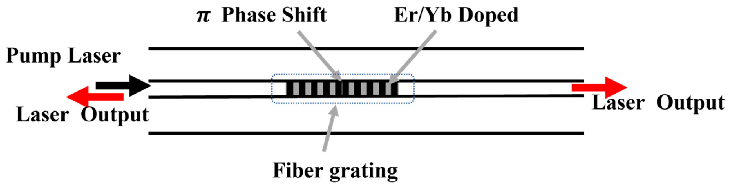
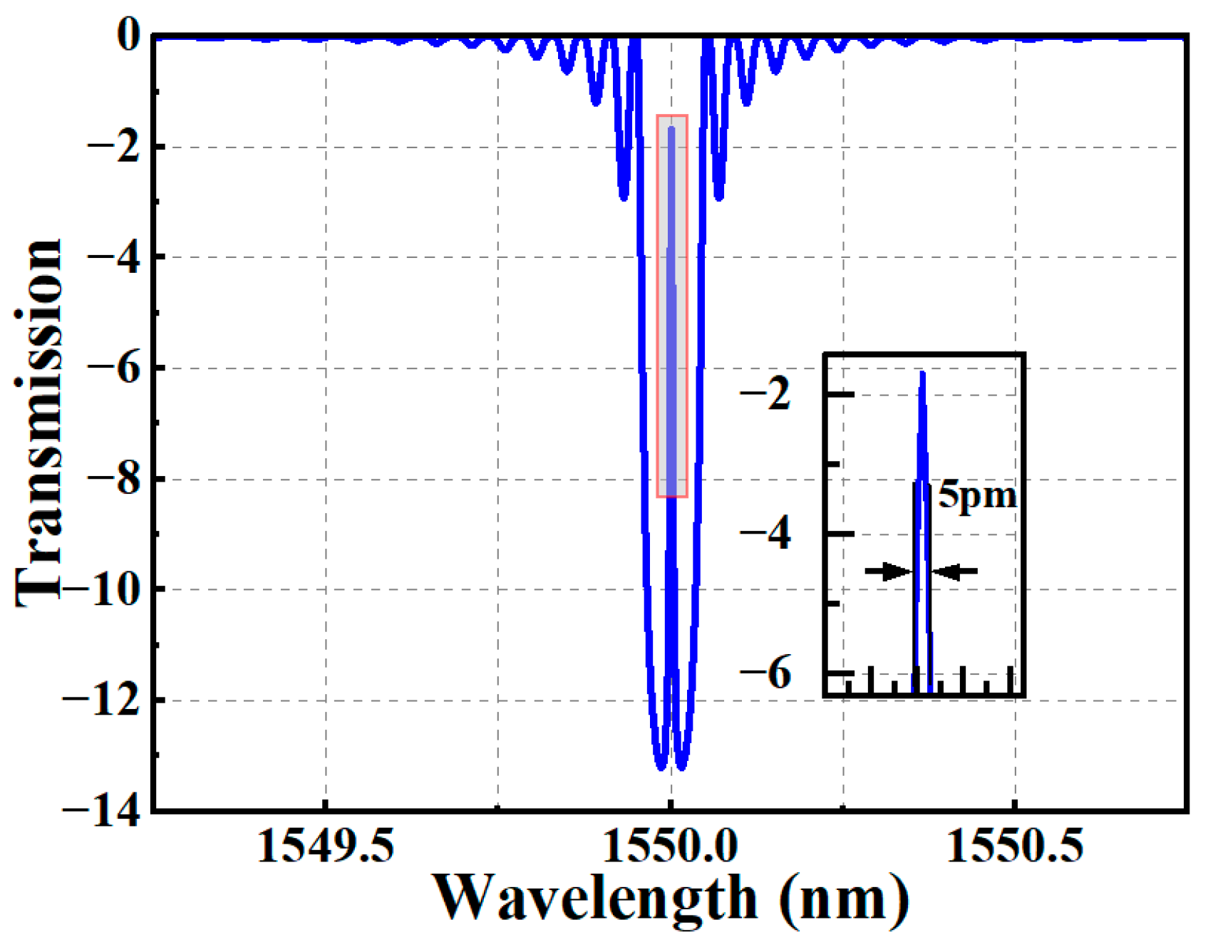
2.1. Simulation of the π-FBG

In this work, the π-FBG is the main sensing element of the DFB-FL-based ultrasound sensor. The modulation of the refractive index of the π-FBG has a phase shift in the central of the grating, as shown in Figure 1, which has a narrow trap in the centra of the transmission spectrum of the π-FBG. When the pump laser is injected into the active fiber cavity, multiple longitudinal mode lasers are generated in the resonant cavity with respect to the cavity length. Considering the ultra-narrow transmission window of the π-FBG, when these longitudinal mode lasers pass through this resonant cavity, only the longitudinal mode with wavelengths in the centra of the transmission window is able to pass through and its linewidth is greatly compressed, while the rest of the longitudinal modes is suppressed.
By using the transmission matrix method, we analyzed and simulated the spectral properties of phase-shifted fiber grating in the active fiber. Assuming the amplitude of the forward wave and backward wave are E A and E B , respectively, when the light passes through the gain grating of length Δz, the transmission equation of the optical field can be expressed as:
E A E B = F E A ( z ) E B ( z )
After taking the phase of grating into account, the transmission matrix F of the DFB-FL is modified to [25]:
F = cosh γ Δ z i Δ β γ sinh γ Δ z exp ( i β b Δ z ) i κ γ sinh γ Δ z exp i ( β b Δ z + φ ) i κ γ sinh ( γ Δ z ) exp i ( β b Δ z + φ ) cosh γ Δ z + i Δ β γ sinh ( γ Δ z ) exp ( i β b Δ z ) ,
where Δ β = i g + 2 n e f f π λ π / Λ , g is the grating unit gain, the optical phase of the j t h segment φ j = φ j 1 + 2 β b Δ z + Δ φ , Δ φ is the mutation phase shift, and   γ   is defined as   κ 2 Δ β 2 . κ is the ac coupling coefficient. Considering the doped Er/Yb ions inside the fiber core, the signal light gain at each position in the DFB-FL can be obtained by calculating the density of doped particles at each energy level, and the laser wavelength and its gain threshold for stable oscillation output can be calculated by using Equation (2).
Figure 2 shows the simulated transmission spectrum of the π-FBG. In the simulation, the length of the fiber grating is set at 4 cm; the period of the π-FBG is set at 534.48 nm; the refractive index modulation is 0.00005; and the phase shift of the fiber grating is set at π. As shown in Figure 2, the transmission spectrum of the π-FBG shows a resistive band near 1550 nm with 5 pm bandwidth.

2.2. Sensing Method

The center wavelength of the phase shifted fiber grating can be calculated by the following equation:
λ B = 2 n e f f Λ
where Λ is the period of the phase shifted grating, and n e f f is the effective refractive index of the grating. When the external ultrasound wave acts on the fiber resonant cavity, the period and the effective refractive index of the optical fiber grating change due to the elastic strain of fiber-optic materials and the elastic-optical effect of the fiber, respectively. The elastic-optical effect on the fiber core induced by ultrasound wave is orders of magnitude smaller than the axis strain. Therefore, we only consider the axial strain induced by the ultrasound wave along the fiber axis. By differentiating both sides of the equation, we can obtain the following equation:
λ = 2 Λ Δ n e f f + 2 Δ Λ n e f f .
Divide Equation (3) by Equation (4):
Δ λ λ B = Δ n e f f n e f f + Δ Λ Λ
The matrix of the elastic-optic constant is shown below [26]:
P = p 11 p 12 p 12 p 12 p 11 p 12 p 12 p 12 p 11 0 0 0 0 0 0 0 0 0 0 0 0 0 0 0 0 0 0 p 44 0 0 0 p 44 0 0 0 p 44
where p 11 and p 12 are the elastic-optic constant of the fiber, which indicate the change in the refractive index in the axial and radial directions due to axial strain, respectively. For isotropic media, p 44 = μ f ( p 12 p 11 ) / 2 , μ f is the Poisson‘s ratio of the fiber core.
The refractive index of the optical fiber along a certain direction can be represented by the dielectric impermeability tensor β i j and dielectric tensor ε i j :
β i j = 1 ε i j = 1 / n i j 2
The relationship between the amount of change in β i j and strain tensor S i j can be described as:
β i j = p i j r s S r s
Assuming there is no shear strain in the fiber, S i j can be expressed as:
S i j = μ f μ f   1   0   0   0   T Λ Λ .
At the same time, the axial strain on the fiber laser can be calculated as:
Δ Λ Λ = ( 1 2 μ f ) P E
For silica fibers, the effective refractive index n e f f is 1.456, and the elastic-optic constant of the fiber is p 11 = 0.121 and p 12 = 0.270 . Poisson’s ratio μ f = 0.17 , P is the pressure of the ultrasound, and E is the Young’s modulus of optical fiber. Thus, we can obtain the output laser frequency change when the ultrasound wave is applied to the DFB-FL:
Δ υ = υ 1 n e f f 2 2 P 12 μ f P 12 + P 11 1 2 μ f P E 0.78 υ 1 2 μ f P E .
According to Equation (11), the output wavelength/frequency changes as the ultrasound wave is subjected to the DFB-FL. By demodulating the amount of wavelength/optical frequency change, the sound pressure magnitude can be measured.

2.3. Demodulation Method

There are several methods to measure the wavelength shift of the output laser of the DFB-FL, including direct wavelength demodulation, beat frequency demodulation, interferometric demodulation, etc. Among of them, the interferometric demodulation method has very high sensitivity, in which an in-fiber Mach–Zehnder interferometer is used to measure the wavelength shift by detecting the amount of change in phase signal by converting it into an interferometric signal due to the small wavelength changes [27].
In this paper, we use an unbalanced Mach–Zehnder interferometer to detect the weak ultrasonic signal. The principle of ultrasound detection is described as follows.
Assuming the wavelength of the output laser of DFB-FL is λ , the interference arm length difference in the MZI is d and the refractive index of the fiber core is n. The amount of change in interferometer phase difference can be expressed as:
Δ φ = 2 π n d λ 2 Δ λ .
The DC component of the signal processed by the balance detector is removed and the output signal can be described as:
I = 2 I 0 R 0 k cos ( 2 π n d λ 2 Δ λ + ϕ 0 )
where I 0 is the intensity of light coupled into the fiber, R 0 is the response of the balance detector and ϕ 0 is the initial phase of the MZI, k = ( I m a x I m i n )/( I m a x + I m i n ) is the contrast of the fringes.
Assuming that the signal to be measured varies according to a sinusoidal law with a frequency of ω s , the amount of change in phase difference in the interferometer at this point is:
Δ ϕ = 2 π n d λ 2 Δ λ = ϕ s sin ω s t
Equation (13) can be rewritten as:
I = 2 I 0 R 0 k cos ϕ 0 cos ( ϕ s sin ω s t ) sin ϕ 0 sin ( ϕ s sin ω s t ) .
Expanding Equation (10) with Bessel function, and considering that when ϕ s 1 , J 0 1 ,     J 1 x x / 2 , only the first two Bessel functions need to be considered, and the light intensity can be expanded as:
I = 2 I 0 R 0 k [ cos ϕ 0 sin ϕ 0 ( ϕ s sin ω s t ) ] .
Equation (15) shows that when ϕ 0 ( 2 m + 1 ) π / 2 , the signal amplitude is at its strongest and the interferometer has the highest sensitivity. When ϕ 0 m π , the amplitude of the signal tends to disappear and the interferometer has the lowest sensitivity.
To maintain optimum sensitivity of system, the MZI needs to operate at an orthogonal operating point where the initial phase difference between the signal light and the reference light is π/2. Thus, in the detection system, a phase modulator and an analog controller were employed in the reference arm to modulate the phase of the light. Also, the PID controller filters out a certain amount of ambient noise interference such as the initial phase fluctuations caused by temperature fluctuations, environmental noise, etc. The signal on the oscilloscope has a linear relationship with the ultrasonic signal to be measured.

3. Experiment and Results

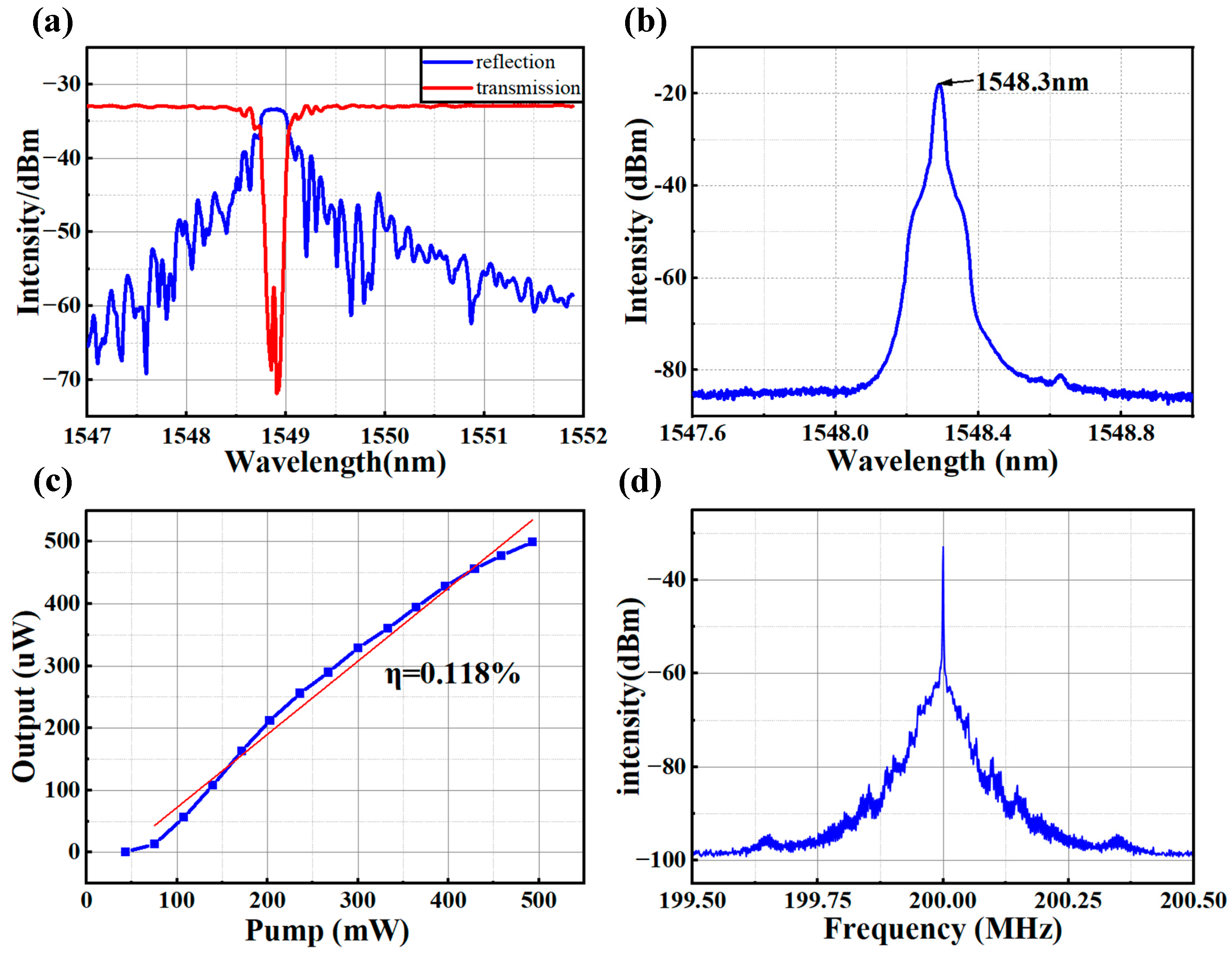
3.1. Laser Output Measurement

In this experiment, the phase-shifted fiber grating is UV-inscribed in the active fiber (Coractive, Quebec City, QC, Canada, EY305) by using the mask scanning method. To suppress the DFB-FL multi-longitudinal-mode oscillations and to reduce the frequency noise, the π -FBG was apodized by using Gaussian function. The transmission spectra of π -FBG was measured and shown in Figure 3a, in which there is a quite narrow transmission window in the center of the transmission spectrum at the wavelength of near 1549 nm. The DFB-FL system is shown in the part of the experiment setup in Figure 4, which consists of the π -FBG, wavelength division multiplexer (WDM) and optical isolator. The pump laser was backward injected into the laser system. As the pump power is higher than 40 mW, the DFB-FL started continuously to output the narrow bandwidth laser at the wavelength of 1548.3 nm, as seen in Figure 3b.
By changing the pump power of the DFB-FL, the slope efficiency of this DFB-FL was measured and plotted in Figure 3c, which shows that the efficiency was about 0.118% with a very high linearity of fit (R2 = 0.984). Furthermore, we use a time-delayed self-centered differential (TCD) to evaluate the linewidth of this fiber laser, which is a delayed non-zero self-heterodyne method based on the Mach–Zehnder interferometer. The linewidth of the measured mixing frequency (beat frequency) power spectrum was twice as much as what the DFB-FL tested [28]. The mixing frequency power spectrum of the TCD is shown in Figure 3d. The measured 3 dB linewidth of the power spectrum is about 22 KHz, which means that the 3 dB linewidth of this DFB-FL is about 11 KHz. The experimental results showed that the DFB-FL output a single-frequency laser, which is suitable for ultrasonic sensing.

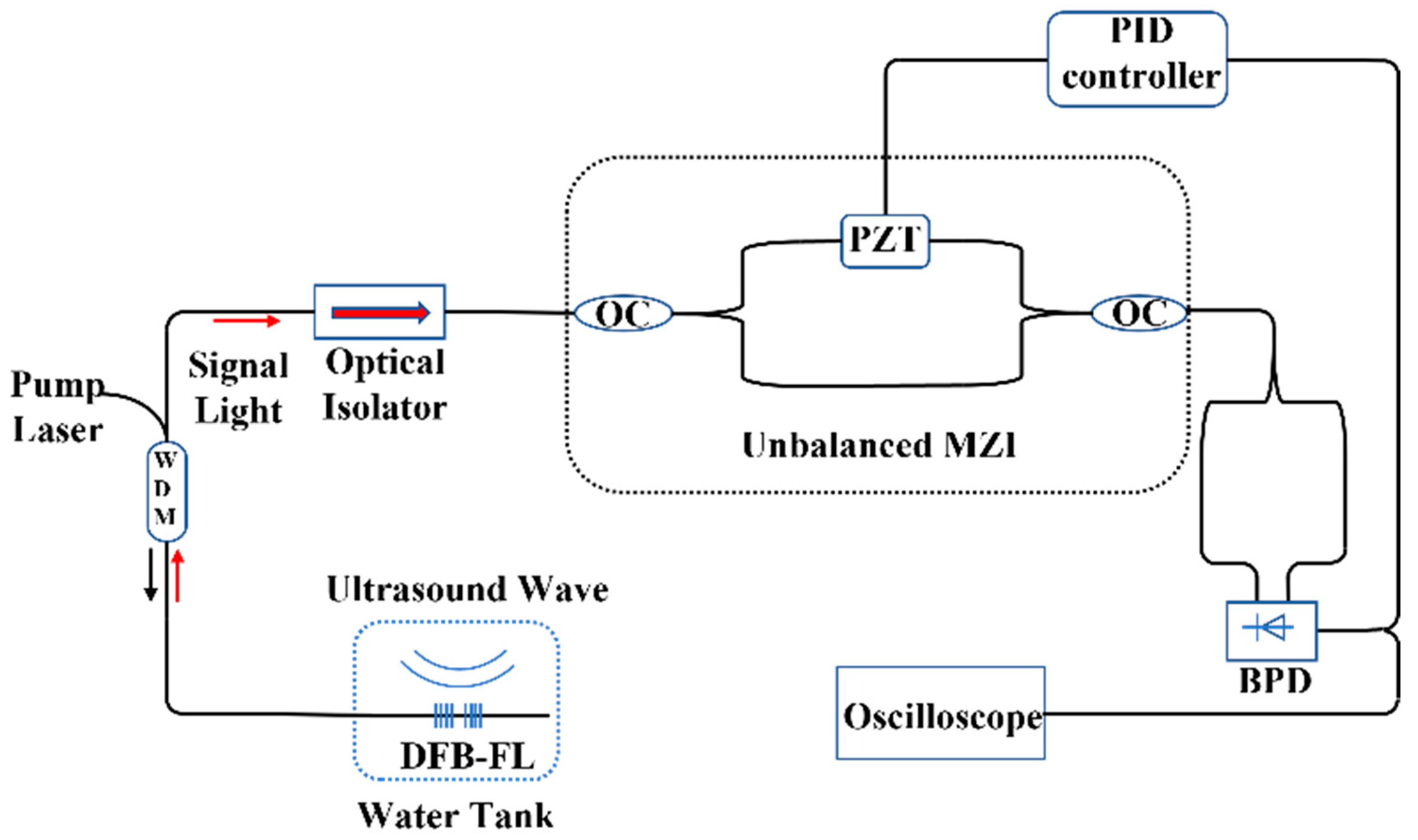
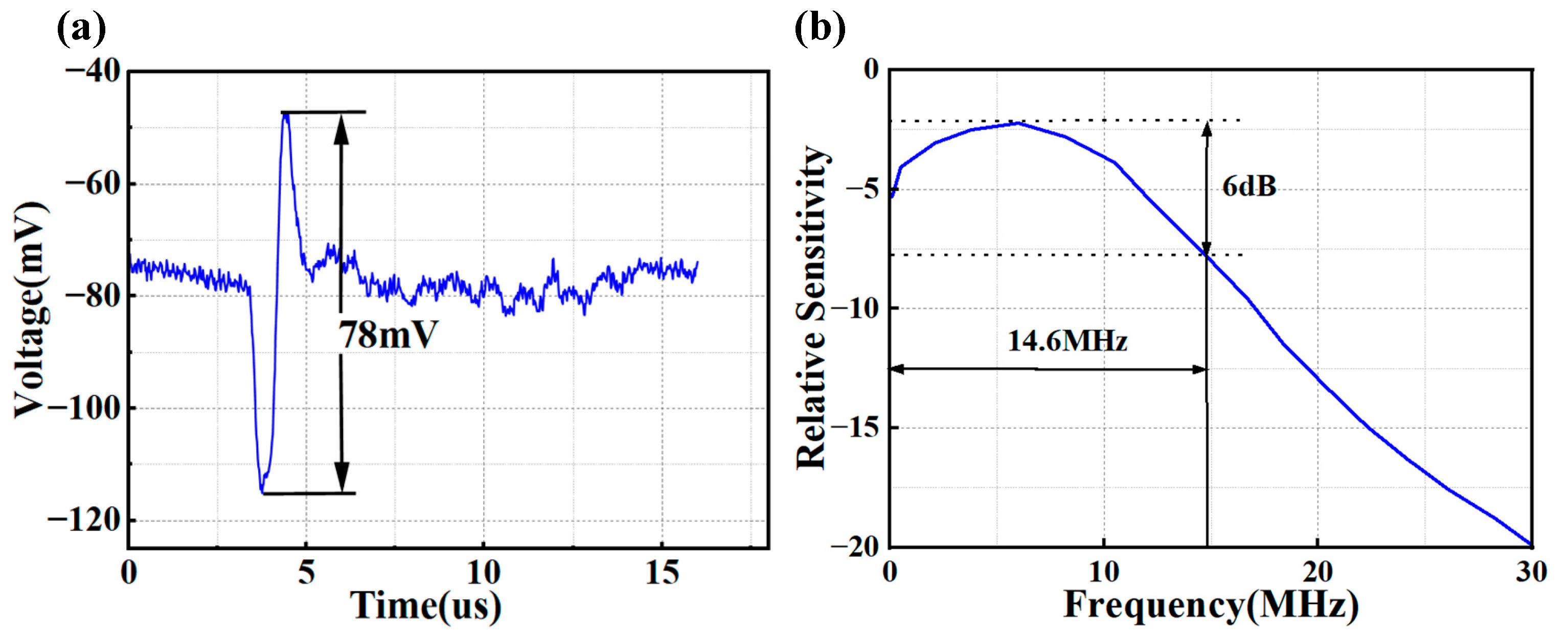
3.2. Ultrasound Sensing Setup and Result
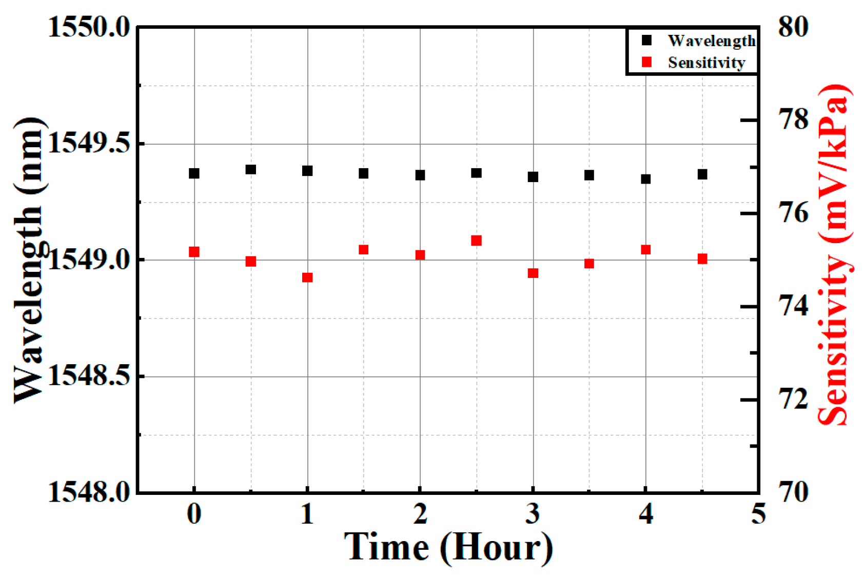
The DFB-FL-based ultrasound sensing system is shown in Figure 4, in which a 980 nm pump laser was connected with a 980/1550 nm Wavelength Division Multiplexer (WDM) to excite the DFB-FL. The Mach–Zehnder interferometer was made of two 50-50 optical couplers. The PZT (PbZrxTi1-xO3) connected in the arm of the Mach–Zehnder interferometer acted as a phase modulator to keep the interferometer at the Q-point by depressing the phase shift caused by the temperature fluctuation and environmental noise. The DFB-FL cavity was placed in the water tank (hydroacoustic cell) to detect the ultrasound signal. The distance between the DFB-FL and the ultrasound generator was set at 1 cm. There was stress applied to the DFB-FL in order to keep it taut and fixed. A conventional piezoelectric hydrophone was placed in the hydroacoustic cell to calibrate the sound pressure intensity. The ultrasound signal was generated by the ordinary unfocused planar electrogenic ultrasound transmitter(Precision acoustics, Dorchester, England). We used a signal generator to output a sinusoidal driving voltage for the ultrasound transmitter. The balance photodetector(Light realism technology corporation, Wuhan, China) was employed to detect the real-time optical signals, depress the DC signal of the MZI and transfer the AC-signal to the oscilloscope(Tektronix MSO54) and back to the PID controller to suppress the phase fluctuations caused by the environmental noise.
First, the frequency of the driving voltage of electrogenic ultrasound transducer was set to 1 MHz to excite the 1MHz ultrasound wave, and the pressure of the ultrasound was set to 5 kPa. The commercial pin type polyvinylidene difluoride (PVDF) hydrophone(Precision acoustics, Dorchester, England) was placed at the opposite direction of the DFB-FL with the same distance from the ultrasound source, as shown in Figure 5.
By changing the pressure of the ultrasound transducer step by step, we can obtain the linear sensitivity curve of the DFB-FL, which had a sensitivity of about 75.18 mV/kPa, and the sensitivity of the hydrophone was around 0.038 mV/kPa. As shown in Figure 5, the output signal intensity of both sensors linearly increases as the sound pressure increases; however, the DFB-FL shows a higher sensitivity to sound pressure. Then, we measured the frequency response of DFB-FL by changing the frequency of the driving voltage of the electrogenic ultrasound transducer from 0.75 MHz to 1.1 MHz with the interval of 10 kHz. As is shown in Figure 6, the frequency of the DFB-FL was quite flat near the 1 MHz, the maximum and minimum difference in sensitivity of the DFB-FL was less than 3 dB.
Due to the limit of the operating bandwidth of piezoelectric material, the electrogenic ultrasound transducer could only output a relatively flat ultrasound amplitude less than 1.1 MHz. To measure the wider frequency response of the DFB-FL, we employed photoacoustic technology to generate a broadband ultrasound signal by shining a pulsed laser with a pulse width of 6 ns and a spot diameter of 5 mm onto a piece of quartz coated with a light-absorbing material. The light-absorbing material absorbed the pulsed laser light to produce thermal expansion and ultimately, broadband ultrasound wave was generated due to the photoacoustic effect. During the measuring process, we placed the central area of the DFB-FL directly opposite the broadband sound source to achieve the highest response of the DFB-FL. The Fourier transform of the measured ultrasound signal yielded the broadband ultrasound frequency response of the DFB-FL which was seen to detect ultrasound signals from 0 to 30 MHz. As is shown in Figure 7, the broadband frequency response of the DFB-FL sensor extended to approximately 30 MHz and the −6 dB bandwidth was 14.6 MHz. The maximum sensitivity appeared to be about 6 MHz. As is shown in the real-time signal, the peak-to-peak signal of the DFB-FL was 78 mV. At the same time, the sensor output signal without ultrasonic signal input was used as the noise signal, and the root mean square noise was obtained as 2 mV in over 30 MHz. It was calculated that the signal-to-noise ratio (SNR) of this DFB-FL was 45.3 dB and the corresponding noise-equivalent pressure was calculated as 0.027 kPa.
Finally, to verify the long-time stability of the sensitivity and the output of the DFB-FL sensor, the sensor was placed on a vibration isolation optical test bench to ensure that the vibrations were all from the ultrasound action. The output wavelength of the DFB-FL was measured by the spectrometer every 30 min, and the sensitivity of the sensor was also measured every 30 min. The results are shown in Figure 8. The output of the DFB-FL remained quite stable in the 5 h. The maximum variations of sensitivity and output wavelength were only 1.06% and 38 pm, respectively.

3.3. Discussion

As shown in the experimental results, the DFB-FL-based ultrasound sensor shows a higher sensitivity, lower noise and broader frequency response band, compared with the traditional piezoelectric ultrasonic sensor. The principle of the piezoelectric ultrasonic sensor is that the ultrasonic vibration pressure was subjected to the piezoelectric ceramic plates to generate the electrical signal. Due to impedance mismatch and material constraints, the bandwidth of the piezoelectric ultrasonic sensors is limited in detecting high-frequency signals, resulting in a narrower response bandwidth. In contrast, the frequency response characteristics of DFB-FL-based sensors are not altered by the resonator, as only the phase of the resonator changes when exposed to ultrasound. Its response bandwidth is solely constrained by the optical fiber material, providing a wider response frequency band compared to piezoelectric ultrasonic sensors. At the same time, the demodulation system based on the unbalanced MZI and PID system maximizes the retention of phase information in the signal, effectively suppressing noise and enabling better detection performance for DFB-FL-based ultrasonic sensors. Furthermore, the sensor is immune to electromagnetic interference and can be applied to sensors for abnormal discharge in the electric power system.

4. Conclusions

In this paper, we theoretically and experimentally demonstrated the DFB-FL-based ultrasound sensor. We theoretically analyzed the transmission method and sensing method of the DFB-FL and the demodulation method of the ultrasound detecting system. The PID algorithm-based modulation method demonstrates excellent suppression of external environmental disturbances. We fabricated the DFB-FL via the phase mask method using the Er/Yb doped fiber and built an unbalanced MZI demodulation system for ultrasound detection. Under experimental tests of different pressure and frequency of the acoustic signals, the high sensitivity and broadband frequency response of this DFB-FL-based ultrasound sensor was proven successfully. The DFB-FL sensor had a 75.18 mV/kPa sensitivity near the 1 MHz ultrasound signal and it had a measurable range of ~30 MHz. The long-term stability of the sensor was also demonstrated, as this sensor was stable for long hours of work.
For the further research, the performance of photoacoustic imaging of this DFB-FL-based ultrasound sensor can be explored.

Author Contributions

Conceptualization, Z.Y and L.Z.; methodology, W.Z.; software, B.Y.; validation, Q.L., R.T. and H.L.; formal analysis, Q.L.; investigation, Q.L.; resources, C.C.; data curation, Q.L.; writing—original draft preparation, C.C.; writing—review and editing, Q.L.; visualization, R.T.; supervision, W.Z.; project administration, Z.Y.; funding acquisition, C.C. All authors have read and agreed to the published version of the manuscript.

Funding

This research received no external funding.

Institutional Review Board Statement

Not applicable.

Informed Consent Statement

Not applicable.

Data Availability Statement

Data are contained within the article.

Acknowledgments

This work was supported by the project of “Distributed Fiber Sensor-based City Cable Monitoring Project” (5215A0230006).

Conflicts of Interest

Author Bo Yang, Rui Tian, Hao Luo and Chao Cai was employed by the State Grid Wuhan Electric Power Supply Company. Author Chao Cai was also employed by the company State Grid Hubei Electric Power Co., Ltd. The remaining authors declare that the research was conducted in the absence of any commercial or financial relationships that could be construed as a potential conflict of interest.

References

  1. Taruttis, A.; Ntziachristos, V. Advances in real-time multispectral optoacoustic imaging and its applications. Nat. Photonics 2015, 9, 219–227. [Google Scholar] [CrossRef]
  2. Qiu, Y.; Gigliotti, J.V.; Wallace, M.; Griggio, F.; Demore, C.E.; Cochran, S.; Trolier-McKinstry, S. Piezoelectric micromachined ultrasound transducer (PMUT) arrays for integrated sensing, actuation and imaging. Sensors 2015, 15, 8020–8041. [Google Scholar] [CrossRef] [PubMed]
  3. Rosenthal, A.; Razansky, D.; Ntziachristos, V. High-sensitivity compact ultrasonic detector based on a pi-phase-shifted fiber Bragg grating. Opt. Lett. 2011, 36, 1833–1835. [Google Scholar] [CrossRef] [PubMed]
  4. Guggenheim, J.A.; Li, J.; Allen, T.J.; Colchester, R.J.; Noimark, S.; Ogunlade, O.; Parkin, I.P.; Papakonstantinou, I.; Desjardins, A.E.; Zhang, E.Z. Ultrasensitive plano-concave optical microresonators for ultrasound sensing. Nat. Photonics 2017, 11, 714–719. [Google Scholar] [CrossRef]
  5. Ma, X.D.; Cai, Y.Q.; Fu, B.; Xu, L.J.; Ma, J.G. Fiber optic-based laser interferometry array for three-dimensional ultrasound sensing. Opt. Lett. 2019, 44, 5852–5855. [Google Scholar] [CrossRef]
  6. Wang, X.X.; Jiang, Y.H.; Li, Z.Y.; Wang, W.; Li, Z.B. Sensitivity Characteristics of Microfiber Fabry-Perot Interferometric Photoacoustic Sensors. J. Light. Technol. 2019, 37, 4229–4235. [Google Scholar] [CrossRef]
  7. Bai, X.; Qi, Y.; Liang, Y.; Ma, J.; Jin, L.; Guan, B.-o. Photoacoustic computed tomography with lens-free focused fiber-laser ultrasound sensor. Biomed. Opt. Express 2019, 10, 2504–2512. [Google Scholar] [CrossRef]
  8. Nuster, R.; Gratt, S.; Passler, K.; Grün, H.; Berer, T.; Burgholzer, P.; Paltauf, G. Comparison of optical and piezoelectric integrating line detectors. In Proceedings of the Photons Plus Ultrasound: Imaging and Sensing, San Jose, CA, USA, 24–29 January 2009; pp. 220–227. [Google Scholar]
  9. Liang, Y.; Jin, L.; Wang, L.; Bai, X.; Cheng, L.; Guan, B.-O. Fiber-laser-based ultrasound sensor for photoacoustic imaging. Sci. Rep. 2017, 7, 40849. [Google Scholar] [CrossRef]
  10. Zhu, Y.; Hu, L.; Liu, Z.; Han, M. Ultrasensitive ultrasound detection using an intracavity phase-shifted fiber Bragg grating in a self-injection-locked diode laser. Opt. Lett. 2019, 44, 5525–5528. [Google Scholar] [CrossRef]
  11. Pang, Y.; Ma, S.; Zhao, X.; Qin, Z.; Liu, Z.; Xu, Y. Broadband high-sensitivity acoustic sensing based on Brillouin random fiber laser. Opt. Laser Technol. 2023, 161, 109195. [Google Scholar] [CrossRef]
  12. Yan, L.S.; Yi, A.; Pan, W.; Luo, B. A simple demodulation method for FBG temperature sensors using a narrow band wavelength tunable DFB laser. IEEE Photonics Technol. Lett. 2010, 22, 1391–1393. [Google Scholar] [CrossRef]
  13. Foster, S.B.; Cranch, G.A.; Harrison, J.; Tikhomirov, A.E.; Miller, G.A. Distributed feedback fiber laser strain sensor technology. J. Light. Technol. 2017, 35, 3514–3530. [Google Scholar] [CrossRef]
  14. Muanenda, Y.; Oton, C.J.; Faralli, S.; Di Pasquale, F. A cost-effective distributed acoustic sensor using a commercial off-the-shelf DFB laser and direct detection phase-OTDR. IEEE Photonics J. 2015, 8, 6800210. [Google Scholar] [CrossRef]
  15. Dandridge, A.; Tveten, A.B.; Giallorenzi, T.G. Homodyne demodulation scheme for fiber optic sensors using phase generated carrier. IEEE Trans. Microw. Theory Tech. 1982, 30, 1635–1641. [Google Scholar] [CrossRef]
  16. Leung, I.; Brodzeli, Z.; Whitbread, T.; Chen, X.B.; Peng, G.D. A distributed-feedback fiber-laser-based optical fiber hydrophone system with very high sensitivity. In Proceedings of the Photonics Asia, Beijing, China, 8–11 November 2004; pp. 434–443. [Google Scholar]
  17. Hansen, L.V.; Kullander, F. Modelling of hydrophone based on a DFB fiber laser. In Proceedings of the 21st International Congress of Theoretical and Applied Mechanics, Warsaw, Poland, 15–21 August 2004. [Google Scholar]
  18. Lovseth, S.W.; Stepanov, D.Y. Analysis of multiple wavelength DFB fiber lasers. IEEE J. Quantum Electron. 2001, 37, 770–780. [Google Scholar] [CrossRef]
  19. Lovseth, S.W.; Stepanov, D.Y. Dynamic analysis of multiple wavelength DFB fiber lasers. IEEE J. Quantum Electron. 2001, 37, 1237–1245. [Google Scholar] [CrossRef]
  20. Foster, S.; Tikhomirov, A.; Milnes, M.; Van Velzen, J.; Hardy, G. A fiber laser hydrophone. In Proceedings of the 17th International Conference on Optical Fibre Sensors, Bruges, Belgium, 23–27 May 2005; pp. 627–630. [Google Scholar]
  21. Goodman, S.; Tikhomirov, A.; Foster, S. Pressure compensated distributed feedback fibre laser hydrophone. In Proceedings of the 19th International Conference on Optical Fibre Sensors, Perth, WA, Australia, 14–18 April 2008; pp. 320–323. [Google Scholar]
  22. Vivek, K.; Rajesh, R.; Sreehari, C.V.; Sham Kumar, S.; Shajahan, K.; Praveen, T.V.; Santhanakrishnan, T.; Moosad, K.P.B. A new approach of large diameter polymer-coated fiber laser hydrophone. J. Light. Technol. 2017, 35, 4097–4104. [Google Scholar] [CrossRef]
  23. Ma, L.; Hu, Y.; Luo, H.; Hu, Z. DFB fiber laser hydrophone with flat frequency response and enhanced acoustic pressure sensitivity. IEEE Photonics Technol. Lett. 2009, 21, 1280–1282. [Google Scholar] [CrossRef]
  24. Yang, L.; Li, Y.; Fang, F.; Li, L.; Yan, Z.; Zhang, L.; Sun, Q. Highly sensitive and miniature microfiber-based ultrasound sensor for photoacoustic tomography. Opto-Electron. Adv. 2022, 5, 200076-1–200076-8. [Google Scholar] [CrossRef]
  25. Erdogan, T. Fiber grating spectra. J. Light. Technol. 1997, 15, 1277–1294. [Google Scholar] [CrossRef]
  26. Xiong, S.D. Fibre Optic Vector Hydrophone Research. Ph.D. Thesis, National University of Defense Technology, Changsha, China, 2004. [Google Scholar]
  27. Liu, Y.; Lin, H.; Dai, Y.; Zhou, A.; Yuan, L. Humidity sensor based on an in-fiber integrated Mach–Zehnder interferometer. IEEE Photonics Technol. Lett. 2019, 31, 393–396. [Google Scholar] [CrossRef]
  28. Cui, M.; Huang, J.; Yang, X. Review on Methods for Laser Linewidth Measurement. Laser Optoelectron. Prog. 2021, 58, 0900005. [Google Scholar]
Figure 1. The schematic of the DFB-FL.
Photonics 11 00654 g001
Figure 2. The simulated transmission spectrum of the π -FBG.
Photonics 11 00654 g002
Figure 3. (a) The measured transmission properties of the π-FBG; (b) the output spectrum of the DFB-FL; (c) the slope efficiency of the DFB-FL; (d) the mixing frequency power spectrum of the DFB-FL.
Photonics 11 00654 g003
Figure 4. The schematic of the ultrasound sensing system.
Photonics 11 00654 g004
Figure 5. (a) The linear fit of the needle-type commercial hydrophone; (b) the linear fit of the sensitivity of the DFB-FL.
Photonics 11 00654 g005
Figure 6. The frequency response of the DFB-FL near 1 MHz.
Photonics 11 00654 g006
Figure 7. (a) The measured output voltage signal of the DFB-FL; (b) the frequency response of the DFB-FL in 30 MHz.
Photonics 11 00654 g007
Figure 8. Long-time stability of the laser sensor.
Photonics 11 00654 g008
Disclaimer/Publisher’s Note: The statements, opinions and data contained in all publications are solely those of the individual author(s) and contributor(s) and not of MDPI and/or the editor(s). MDPI and/or the editor(s) disclaim responsibility for any injury to people or property resulting from any ideas, methods, instructions or products referred to in the content.

