Communication

Output Characteristics of External-Cavity Mode-Hop-Free Tunable Laser Source in C+L Band

1
College of Intelligence Science and Technology, National University of Defense Technology, Changsha 410073, China
2
Ceyear Technologies Co., Ltd., Qingdao 266555, China
3
Beijing Institute of Control and Electronic Technology, Beijing 100000, China
4
Science and Technology on Electronic Test & Measurement Laboratory, Qingdao 266555, China
5
Shandong Electronic Test & Measurement Technology Innovation Center, Qingdao 266555, China
6
State Key Laboratory of Modern Optical Instrumentation, College of Optical Science and Engineering, Zhejiang University, Hangzhou 310027, China
*
Authors to whom correspondence should be addressed.
Photonics 2024, 11(7), 677; https://doi.org/10.3390/photonics11070677
Submission received: 22 June 2024 / Revised: 12 July 2024 / Accepted: 19 July 2024 / Published: 21 July 2024
(This article belongs to the Special Issue Emerging Topics in High-Power Laser and Light–Matter Interactions)

Abstract

:
Tunable laser sources with a wide wavelength tuning range, mode-hop-free (MHF) operation, and high spectral purity are essential for applications such as high-resolution spectroscopy, coherent detection, and intelligent fiber sensing. In this paper, we present a wide-range tunable laser source that operates without mode hopping, based on external cavity feedback using a semiconductor gain chip as the laser gain medium. The wavelength, power, and spectral characteristics of the laser are experimentally measured. A wide MHF continuous wavelength tuning range from 1480 nm to 1620 nm with a side-mode suppression ratio of more than 61.65 dB is achieved. An output optical power of more than 11.14 dBm with good power stability can also be realized in the full C+L band. This proposed external-cavity tunable laser source features a narrow intrinsic linewidth and MHF tunable radiation with a maximum sweep speed of 200 nm/s, enabling practical applications such as high-resolution vector spectrum analysis.

1. Introduction

The development of the first laser [1], using a ruby crystal as the gain medium, marked a milestone in the academic community, sparking extensive research into new laser technologies [2,3,4,5,6,7,8,9], particularly semiconductor diode lasers that utilize a semiconductor as the gain medium [10,11,12]. Semiconductor diode lasers (also known as diode lasers) have opened avenues for numerous applications, including frequency and timing metrology [13,14,15], laser cooling [16], coherent optical communication [17], and optical fiber sensing [18,19,20,21]. Additionally, it is worth mentioning that semiconductor lasers now serve as efficient pump sources for crystal gain media [22,23,24]. Across these fields, external-cavity tunable laser sources (EC-TLSs) with flexible and controllable emission characteristics have become the primary consideration in the above application fields. The demands of the ever-growing mode-hop-free (MHF) tuning range have resulted in the development of various novel external-cavity configurations. Up to now, the structure of EC-TLSs has been classified into the two most common types, namely the Littrow and Littman–Metcalf geometries. An EC-TLS with a wide tuning range of 173 nm based on the Littrow geometry was reported by K. Fedorova et al., where the output spectral linewidth and side mode suppression ratio (SMSR) are less than 400 pm and 50 dB at around 1550 nm, respectively [25]. Wang et al. demonstrated that the diode laser chip in conjunction with an external optical feedback provided by a high first-order diffraction efficiency (about 91%) dispersion element can significantly improve the characteristics of the EC-TLS based on the Littrow structure and obtain a 209.9 nm tunable range [26]. Although wide tunable ranges have been obtained, little attention has been paid to the MHF output characteristics in the work mentioned above. In addition, the 0th-order lasing output beam steers used as the dispersion element (usually grating) are rotated in order to change the lasing wavelength. Therefore, the application range of the Littrow cavity laser is limited.
Compared with the classical Littrow cavity, the Littman–Metcalf configuration incorporates an additional mirror. Tuning in the Littman–Metcalf configuration is achieved by mechanically rotating the mirror angle rather than adjusting the incidence angle of the dispersion unit. This design allows the output beam direction to remain fixed as the lasing wavelength is tuned. The Littman–Metcalf cavity can be designed to increase the tuning range in which continuous MHF tuning is possible. An EC-TLS based on the traditional Littman–Metcalf design was reported by Gong et al., where the maximum MHF tunable range of 78 GHz was measured operating at 774.5 nm [27]. The proposed EC-TLS operated under an unoptimized reflector pivot position. An about 59.13 nm continuous MHF tuning range EC-TLS with a Littman–Metcalf geometry based on a diffraction grating was reported by Zhang et al., with an optical signal to noise ratio (OSNR) of around 65 dB and a spectral linewidth of less than 100 kHz [12]. By corotating a periscope with an etalon and a 0.8 nm (full width half maximum) narrow bandpass filter inside a modified Littman–Metcalf configuration, Zhu et al. demonstrated a novel MHF tunable EC-TLS without mechanical pivot-point tuning with a maximum linewidth of around 1 MHz, where the proposed Littman–Metcalf cavity had a MHF continuous tuning range of 1.7 THz [28]. At present, many scholars are inclined to the study of EC-TLSs based on the Littman–Metcalf geometry with a wider tuning range, but the research of continuous wavelength tuning with MHF is rarely reported.
In this study, we present a MHF laser system with a wide continuous wavelength tuning range based on the traditional Littman–Metcalf geometry, maintaining the narrow output spectral linewidth and high SMSR advantages of typical EC-TLSs. The output characteristics of the designed EC-TLS are investigated in detail. Experimentally, a continuously tunable range of about 140 nm with no mode hopping is achieved, which is an about 71.4% times enhancement compared with the reference [9], and the SMSR over the entire wavelength tuning output range is estimated to be better than 61.65 dB. Using self-heterodyne interferometry, the laser intrinsic linewidth is measured to be less than 5.37 kHz at the emitting wavelength of 1570 nm, and the maximum output power of the designed EC-TLS is about 15.95 dBm. In addition, a high power stability of ±0.024 dB/1 h and wavelength stability of ±3.08 pm/1 h are obtained, respectively. The significant advantage of this proposed EC-TLS is its ability to tune the lasing wavelength finely over a wide range without mode hopping, thus making it suitable for practical applications such as ultra-high spectral analysis systems.

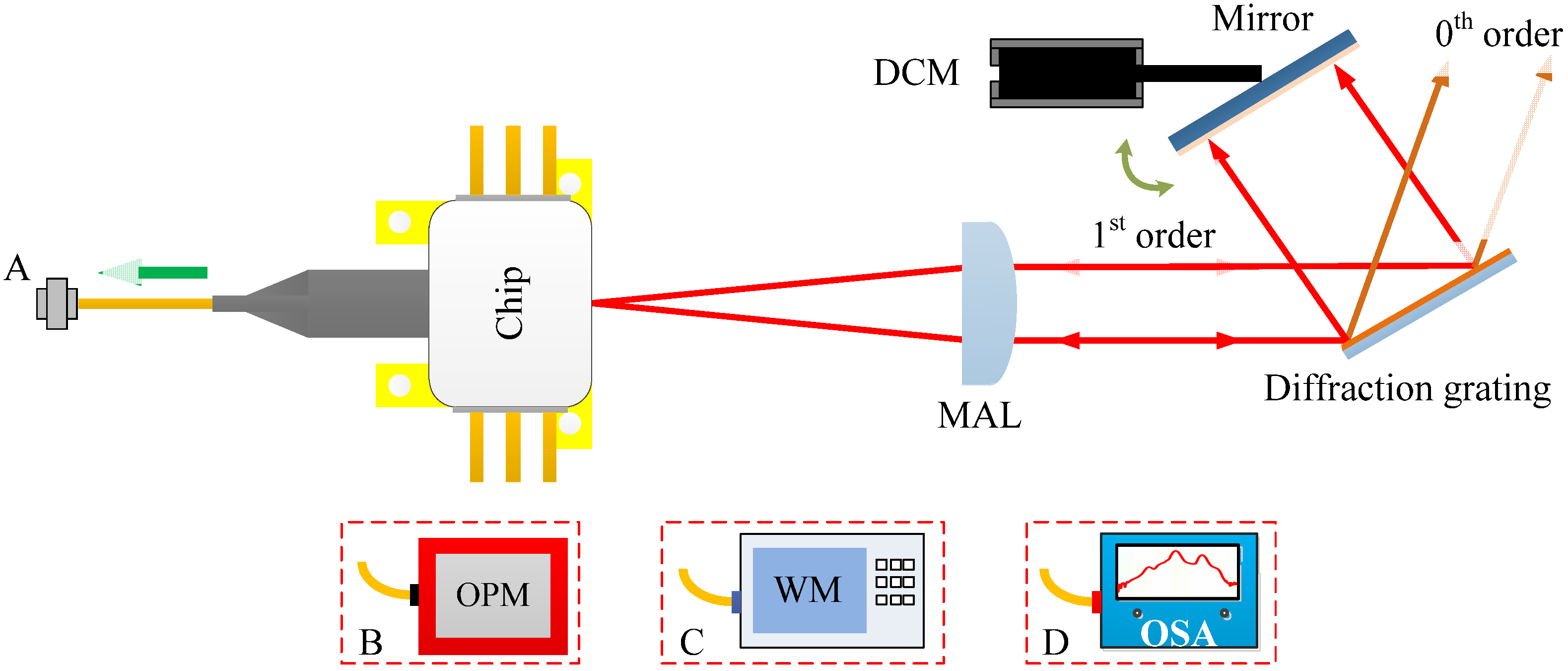
2. Configuration of the EC-TLS and Device Characteristics

The configuration of the proposed laser is illustrated in Figure 1. The commercially available gain chip (Thorlabs, SAF1150S2) employs a multi-quantum well and ridge waveguide structure, achieving an output bandwidth of 133.3 nm centered at a typical wavelength of 1521.7 nm. The length of the gain chip is about 1 mm, and it is coated with a 0.05% anti-reflection film on its angled facet and a 10% reflectivity film on the other side. This gain chip is powered by a custom-built, ultra-low-noise current driver capable of supplying a maximum output current of 400 mA. Additionally, it is cooled to approximately 25.0 °C using a 7.56 W thermoelectric cooler. The output laser beam from the gain chip is shaped by a molded aspherical lens (Edmund, #87-155). The plano side and aspherical side of the collimating lens are coated with anti-reflection film, its numerical aperture is 0.55, and the focal length is 4.51 mm. The shaped laser beam is incident on the surface of the optical feedback element. Feedback is provided by a gold-coated blazed diffraction grating with 900 lines per mm (Newport Richardson, 33025FL01-155R). The average diffraction efficiency into the 1st-order is around 75% if the polarization of the gain chip is oriented perpendicular to the lines of the grating. The blazed diffraction grating, measuring 15 mm × 6 mm × 6 mm, provides a sufficient tuning range for diffracted wavelengths without clipping the lasing edges of the optical feedback element. The first-order diffracted beam is retroreflected by an added mirror back into the active layer, where it is amplified. The tuning of the selected mode is achieved by adjusting the added mirror, which is driven by a brushless direct current (DC) motor, relative to the incident beam. The fiber in this setup transmits the tunable laser signals and connects with other test instruments through port A to characterize the output characteristics of the proposed EC-TLS. As we have reported in ref. [29], to expand the wavelength tuning range of the proposed EC-TLS, here we adopt a new collimation method that requires the distance between the waist position and molded aspherical lens to be equal to the length of the external cavity.
The B port of the optical power meter (Ceyear, 6337D) is connected to output port A to characterize power-related properties such as the threshold current, peak output power, and power stability. By connecting the C port of the wavelength meter (Yokogawa, AQ6151B) or the D port of the optical spectrum analyzer (Ceyear, 6362D) with a set resolution of 10 pm, wavelength-related characteristics including the tuning range and wavelength stability can be measured.

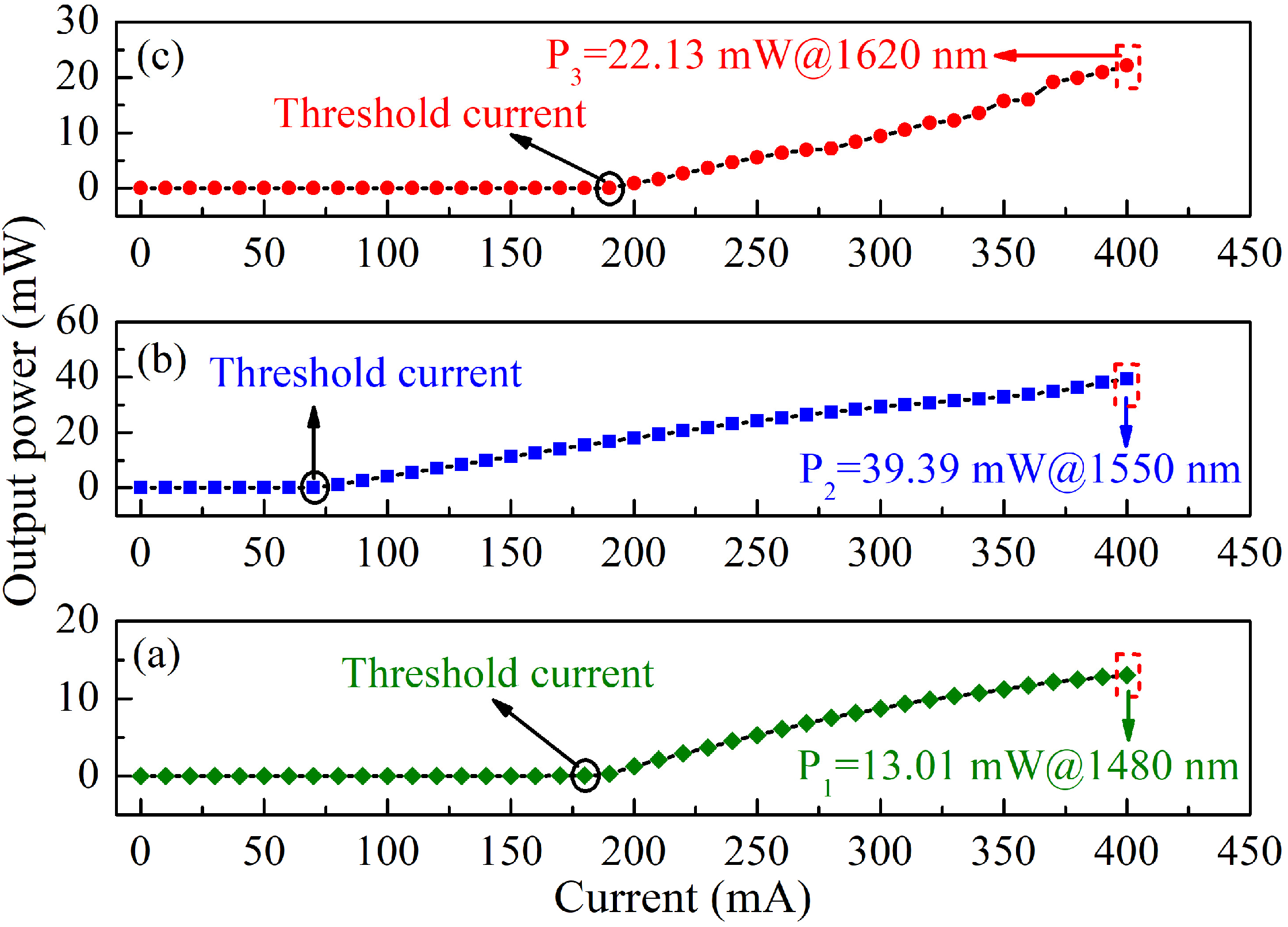
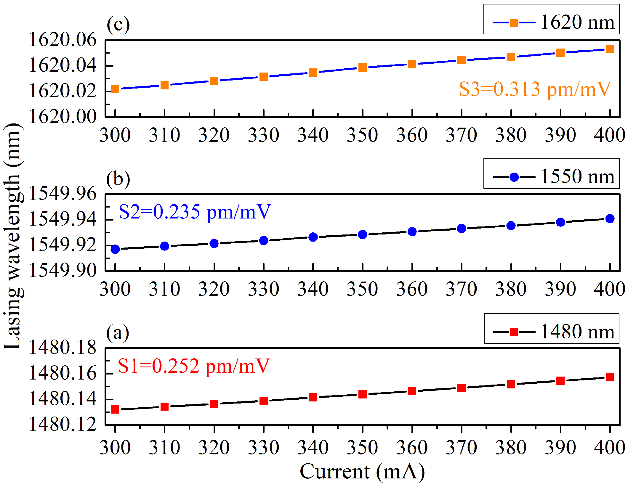
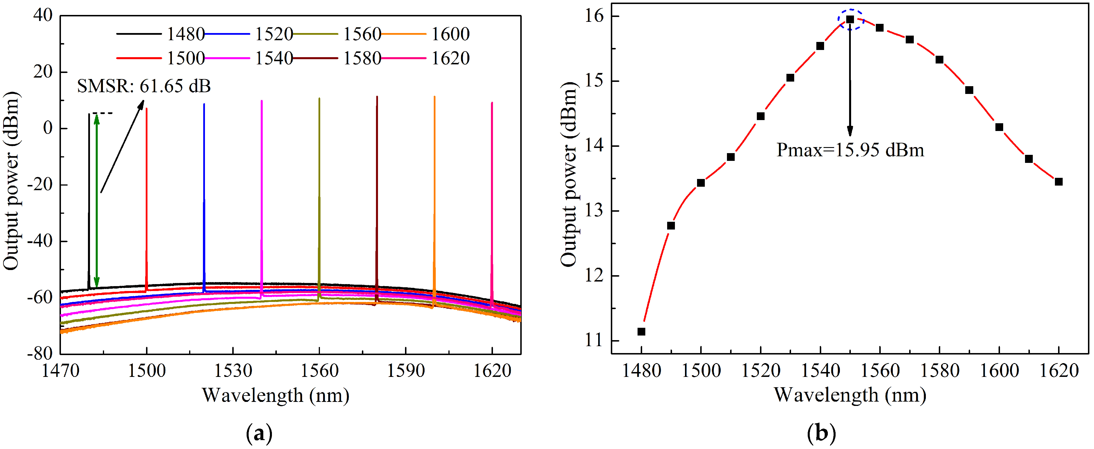
3. Results and Discussion

After constructing the experimental system, the performance of the laser source with the added external cavity was initially observed. The typical P-I curves of the laser source, optimized by external optical feedback, are shown in Figure 2. Figure 2a depicts the P-I plot when the resonant output wavelength is in the short wavelength region. The threshold current is approximately 180 mA at 1480 nm, and the maximum output power reaches 13.01 mW (11.14 dBm). Figure 2b shows the P-I curve at 1550 nm, indicating a threshold current of about 70 mA and a maximum output power of approximately 39.39 mW (15.95 dBm), a significant increase compared to the gain chip’s output power of 0.12 mW without external optical feedback (as per the supplier’s test report). The experimental results demonstrate that the laser system operates under strong optical feedback conditions and achieves optimal alignment. Figure 2c shows that at 1620 nm, the threshold current is about 190 mA, and the maximum output power is approximately 22.13 mW (13.45 dBm). The observed variation in the threshold current, decreasing and then increasing as the lasing wavelength changes from 1480 nm to 1620 nm, is primarily due to the spectral gain profile of the gain chip. To achieve a wider tuning range and higher output power, the operating current is set to 400 mA, leveraging the drive capability of the homemade laser diode driver, which is well above the maximum threshold current.
Meanwhile, the relationship between the lasing wavelength and the injection current is studied. As shown in Figure 3, the maximum slope is only 0.313 pm/mV, which implies that the proposed laser source has strong robustness, that is, mode hopping occurs when the injection current fluctuates by more than 80 mV instantaneously. In fact, this phenomenon is different from the experimental results we observed before, and we infer that the probability of this result is due to the difference in the parameters of the gain chip itself.
Figure 4a shows the spectra of the tunable laser source at an injection current of 400 mA. It can be seen from the figure that at this time, the lasing output wavelength of the EC-TLS can be changed from 1480 nm to 1620 nm with an about 20 nm/step; that is, the tuning range is about 140 nm, and the spectrogram shows a single longitudinal mode operation, with a minimum SMSR of about 61.65 dB. The output optical power at different lasing wavelengths is then tested using a self-developed power meter produced by Ceyear. As seen in Figure 4b, the output optical power varies with the lasing wavelength. The maximum and minimum output powers of the EC-TLS are 15.95 dBm and 11.14 dBm, respectively. Clearly, with an injection current of 400 mA, an output power exceeding 11.14 dBm can be achieved across the entire C+L band.
For our proposed EC-TLS, the maximum axial mode spacing is close to 26.2 pm operating at 1620 nm, which is due to the designed cavity length of about 50 mm. In practice, the smaller the axial mode spacing, i.e., the closer to 21.9 pm, the shorter the resonant output wavelength. Therefore, when the first-order or second-order difference in the adjacent output wavelength test data is less than the minimum axial mode spacing, it indicates that the laser system operates in a MHF tunable output throughout the entire band. As displayed in Figure 5a, according to the test results, the maximum and minimum wavelength differences are calculated to be 16.12 pm and −1.6 pm, respectively. Meanwhile, an experiment is carried out to investigate the sweep speed based on the classical optical frequency domain reflectometer (OFDR) scheme [21]. Figure 5b shows that the tuning range of 80 nm is 0.401 s, that is, the sweep speed is estimated at 200 nm/s. In addition, the inset plotted in Figure 4b indicates that the proposed EC-TLS can operate in a MHF state because no phase mutations are observed.
The corresponding output wavelength and power stability curves of the tunable laser source in the case of one hour of continuous output (sample rate: 1 Hz) at an injection current of 400 mA and a controlled ambient temperature of 22 ± 1 °C are shown in Figure 6a and Figure 6b, respectively. According to the results, the peak-to-valley or root-mean-square (RMS) values of the wavelength stability and output power of the laser configuration can be calculated as ±3.08 pm/1 h or ±0.961 pm/1 h and ±0.024 dB/1 h or ±0.0095 dB/1 h, respectively, indicating that the tunable laser source has good wavelength and output power long-term stability.
The intrinsic linewidth of the EC-TLS is measured using an optical noise analyzer fabricated by SYCATUS. Figure 7 illustrates the relationship between the intrinsic linewidth and the resonant output wavelength. As shown in Figure 7, the intrinsic linewidth of the output laser beam remains below 10.13 kHz within the 140 nm tuning range. Notably, when the resonant output wavelength approaches 1570 nm, the intrinsic linewidth is further reduced to 5.37 kHz. This performance is attributed to the design and manufacture of the low-noise current driver and the long-term stability of the external cavity.

4. Conclusions

In this paper, we have successfully constructed a wide-range, MHF tunable laser source based on external cavity feedback using a semiconductor gain chip and performed an analysis of its output characteristics. Our wavelength analysis revealed a tuning range of 140 nm without mode hopping, an RMS wavelength stability of ±0.961 pm over 1 h, and a maximum sweep speed of 200 nm/s. The optical power analysis demonstrated that the tunable laser source achieves an output power exceeding 11.14 dBm across the full C+L band, with an RMS power stability of ±0.0095 dB for over one hour at a continuous injection current of 400 mA. The spectral analysis showed that the intrinsic linewidth of the laser system is less than 10.13 kHz, and that the minimum side-mode suppression ratio is 61.65 dB. This externally coupled tunable laser source shows potential for application in high-resolution vector spectrum analysis for the discovery and understanding of various materials.

Author Contributions

Conceptualization, J.S. and L.S.; methodology, L.Q.; software, L.L.; validation, J.S. and M.P.; investigation, L.H.; resources, F.N.; data curation, Y.C.; writing—original draft preparation, J.S.; writing—review and editing, L.S. and J.H.; visualization, L.Q.; supervision, L.S., L.H., M.P., Y.C. and J.H.; project administration, F.N.; funding acquisition, L.S. All authors have read and agreed to the published version of the manuscript.

Funding

This research was funded by National Natural Science Foundation of China, grant number U23B2046; National Key R&D Program of China, grant numbers 2022YFF0705900 and 2022YFF0707102.

Institutional Review Board Statement

Not applicable.

Informed Consent Statement

Not applicable.

Data Availability Statement

Data are contained within the article.

Conflicts of Interest

The authors declare no conflicts of interest.

References

  1. Maiman, T.H. Stimulated optical radiation in ruby. Nature 1960, 187, 493–494. [Google Scholar] [CrossRef]
  2. Lv, Z.W.; Liu, Z.Z.; Chen, H.; Jin, D.; Hao, X.; Fan, W.Q.; Wang, Y.L.; Bai, Z.X. Review of multi-wavelength laser technology based on crystalline Raman conversion (invited). Infrared Laser Eng. 2023, 52, 20230420. [Google Scholar]
  3. Shank, C.; Bjorkholm, J.; Kogelnik, H. Tunable distributed-feedback dye laser. Appl. Phys. Lett. 1971, 18, 395–396. [Google Scholar] [CrossRef]
  4. Chen, H.; Cui, Y.; Li, X.; Zhang, B.; Cai, Y.; Ding, J.; Qi, Y.Y.; Yan, B.Z.; Wang, Y.L.; Lv, Z.W.; et al. High-power dual-wavelength intracavity diamond Raman laser. Funct. Diam. 2023, 3, 2282527. [Google Scholar] [CrossRef]
  5. Zhang, Y.K.; Chen, H.; Bai, Z.A.; Pang, Y.J.; Wang, Y.L.; Lv, Z.W.; Bai, Z.X. Multi-wavelength red diamond Raman laser. Infrared Laser Eng. 2023, 52, 20230329. [Google Scholar]
  6. Bai, Z.X.; Zhao, Z.A.; Tian, M.H.; Jin, D.; Pang, Y.J.; Li, S.S.; Yan, X.S.; Wang, Y.L.; Lv, Z.W. A comprehensive review on the development and applications of narrow-linewidth lasers. Microwave Opt. Technol. Lett. 2022, 64, 2244–2255. [Google Scholar] [CrossRef]
  7. Chen, Y.F.; Tan, B.W.; Jin, D.; Chen, B.; Bai, Z.X.; Wang, K.; Wang, Y.L.; Lv, Z.W. Characteristics and suppression of beam distortion in a high repetition rate nanosecond stimulated Brillouin scattering phase conjugation mirror. High Power Laser Sci. Eng. 2024, 12, e20. [Google Scholar] [CrossRef]
  8. Chen, B.; Bai, Z.X.; Zhao, G.J.; Wang, Y.L.; Lv, Z.W. Generation of high-efficiency hundred-millijoule stimulated Brillouin scattering in fused silica. Infrared Laser Eng. 2023, 52, 20230421. [Google Scholar]
  9. Kasai, K.; Nakazawa, M.; Tomomatsu, Y.; Endo, T. 1.5 μm, mode-hop-free full C-band wavelength tunable laser diode with a linewidth of 8 kHz and a RIN of −130 dB/Hz and its extension to the L-band. Opt. Express 2017, 25, 22113–22124. [Google Scholar] [CrossRef]
  10. Sheng, L.W.; Ge, C.L.; Cao, Q.T.; Huang, L.; Zhao, Z.A.; Li, L.F.; Qiao, S.; Zhang, A.G.; Wei, Y.; Jin, H.; et al. Wide-range external-cavity tunable semiconductor laser with mode-hopping free. Infrared Laser Eng. 2023, 52, 20230374. [Google Scholar]
  11. Mroziewicz, B. External cavity wavelength tunable semiconductor lasers-a review. Opto-Electronics Rev. 2008, 16, 347–366. [Google Scholar] [CrossRef]
  12. Zhang, A.G.; Qiao, S.; Sheng, L.W.; Huang, L.; Liu, Z.M.; Ju, J.W.; Zhang, Z.H.; Yin, B.Q.; Li, P.; Liu, J.Q.; et al. Study on external cavity diode laser with a wide mode-hopping free tuning range. Front. Phys. 2022, 10, 1093179. [Google Scholar] [CrossRef]
  13. McGrew, W.F.; Zhang, X.; Fasano, R.J.; Schäffer, S.A.; Beloy, K.; Nicolodi, D.; Brown, R.C.; Hinkley, N.; Milani, G.; Schioppo, M.; et al. Atomic clock performance enabling geodesy below the centimetre level. Nature 2018, 564, 87–90. [Google Scholar] [CrossRef] [PubMed]
  14. Schioppo, M.; Brown, R.C.; McGrew, W.F.; Hinkley, N.; Fasano, R.J.; Beloy, K.; Yonn, T.H.; Milani, G.; Nicolodi, D.; Sherman, J.A.; et al. Ultrastable optical clock with two cold-atom ensembles. Nat. Photonics 2017, 11, 5163–5166. [Google Scholar] [CrossRef]
  15. Zhang, L.B.; Liu, T.; Chen, L.; Xu, G.J.; Jiang, C.H.; Liu, J.; Zhang, S.G. Development of an interference filter-stabilized external-cavity diode laser for space applications. Photonics 2020, 7, 12. [Google Scholar] [CrossRef]
  16. Chi, M.J.; Jensen, O.B.; Petersen, P.M. Tuning range and output power optimization of an external-cavity GaN diode laser at 455 nm. Appl. Optics 2016, 55, 2263–2269. [Google Scholar] [CrossRef]
  17. Ma, Y.R.; Yang, Q.; Tang, Y.; Chen, S.M.; Shieh, W. 1-Tb/s single-channel coherent optical OFDM transmission over 600-km SSMF fiber with subwavelength bandwidth access. Opt. Express 2009, 17, 9421–9427. [Google Scholar] [CrossRef]
  18. Ding, Z.Y.; Yao, X.S.; Liu, T.G.; Du, Y.; Liu, K.; Jiang, J.F.; Meng, Z.; Chen, H.X. Compensation of laser frequency tuning nonlinearity of a long range OFDR using deskew filter. Opt. Express 2013, 21, 3826–3834. [Google Scholar] [CrossRef]
  19. Leviatan, E.; Eyal, A. High resolution DAS via sinusoidal frequency scan OFDR (SFS-OFDR). Opt. Express 2015, 24, 33318–33334. [Google Scholar] [CrossRef]
  20. Yin, G.L.; Lu, L.; Zhou, L.; Shao, C.; Fu, Q.J.; Zhang, J.D.; Zhu, T. Distributed directional torsion sensing based on an optical frequency domain reflectometer and a helical multicore fiber. Opt. Express 2020, 28, 16140–16150. [Google Scholar] [CrossRef]
  21. Luo, M.M.; Liu, J.F.; Tang, C.J.; Wang, X.F.; Lan, T.; Kan, B.X. 0.5 mm spatial resolution distributed fiber temperature and strain sensor with position-deviation compensation based on OFDR. Opt. Express 2019, 27, 35823–35829. [Google Scholar] [CrossRef] [PubMed]
  22. Paliesek, T.; Navrátil, P.; Pilař, J.; Divoký, M.; Smrž, M.; Mocek, T. Beam shaping in the high-energy kW-class laser system Bivoj at the HiLASE facility. High Power Laser Sci. Eng. 2023, 11, e79. [Google Scholar] [CrossRef]
  23. Bai, Z.X.; Chen, H.; Gao, X.Q.; Li, S.S.; Qi, Y.Y.; Bai, Z.A. Highly compact nanosecond laser for space debris tracking. Op. Materials 2019, 98, 109470. [Google Scholar] [CrossRef]
  24. Li, K.; Song, C.Y.; Yue, J.F.; Jia, M.Y.; Xu, Z.P.; Wu, D.; Cao, C.; Bai, Z.X.; Yu, Y.; Wang, Y.L.; et al. 500 Hz Joule-level output by sub-nanosecond Zig-Zag slab laser. Infrared Laser Eng. 2023, 52, 20230423. [Google Scholar]
  25. Fedorova, K.A.; Cataluna, M.A.; Kudryashov, I.; Khalfin, V.; Rafailov, E.U. Broadly tunable InGaAsP-InP strained multi-quantum-well external cavity diode laser. IEEE Photon. Technol. Lett. 2010, 22, 1205–1207. [Google Scholar] [CrossRef]
  26. Wang, Y.; Wu, H.; Chen, C.; Zhou, Y.L.; Wang, Y.B.; Liang, L.; Tian, Z.H.; Qin, L.; Wang, L.J. An ultra-high-SMSR external-cavity diode laser with a wide tunable range around 1550 nm. Appl. Sci. 2019, 9, 4390. [Google Scholar] [CrossRef]
  27. Gong, H.; Liu, Z.G.; Zhou, Y.L.; Zhang, W.B. Extending the mode-hop-free tuning range of an external-cavity diode laser by synchronous tuning with mode matching. Appl. Opt. 2014, 53, 7878–7884. [Google Scholar] [CrossRef] [PubMed]
  28. Zhu, J.Y.; Qiao, D.; Jones, A.; Zhang, B.; Li, K.; Copner, N. 1.7 THz tuning range pivot-point-independent mode-hop-free external cavity diode laser. Opt. Express 2023, 31, 3970–3983. [Google Scholar] [CrossRef]
  29. Dong, J.T.; Chen, Z.W.; Sheng, L.W.; Huang, L. Collimation system of external cavity tunable diode lasers (invited). Electro-Opt. Technol. Appl. 2024, 39, 56–59. [Google Scholar]
Figure 1. Schematic drawing of the proposed EC-TLS. MAL, molded aspherical lens; DCM, direct current motor; OPM, optical power meter; WM, wavelength meter; OSA, optical spectrum analyzer.
Photonics 11 00677 g001
Figure 2. P-I curves of the laser source: (a) P-I plot of the laser source operating at 1480 nm; (b) P-I plot of the laser source operating at 1550 nm; (c) P-I curve of the laser source operating at 1620 nm.
Photonics 11 00677 g002
Figure 3. Lasing wavelength as a function of the injection current: (a) wavelength–injection plot of the laser source operating at 1480 nm; (b) wavelength–injection plot of the laser source operating at 1550 nm; (c) wavelength–injection curve of the laser source operating at 1620 nm.
Photonics 11 00677 g003
Figure 4. (a) Spectrogram of the proposed EC-TLS at different resonant output wavelengths; (b) the relationship between the output power and the resonant output wavelength.
Photonics 11 00677 g004
Figure 5. (a) MHF performance of the proposed EC-TLS; (b) sweep speed performance of the proposed tunable laser source.
Photonics 11 00677 g005
Figure 6. (a) Output wavelength stability curve of the tunable laser source; (b) output optical power stability curve of the tunable laser source.
Photonics 11 00677 g006
Figure 7. The relationship between the intrinsic linewidth and the resonant output wavelength.
Photonics 11 00677 g007
Disclaimer/Publisher’s Note: The statements, opinions and data contained in all publications are solely those of the individual author(s) and contributor(s) and not of MDPI and/or the editor(s). MDPI and/or the editor(s) disclaim responsibility for any injury to people or property resulting from any ideas, methods, instructions or products referred to in the content.

