Article

Polarization Analysis of Vertically Etched Lithium Niobate-on-Insulator (LNOI) Devices

1
National Laboratory of Solid State Microstructures, School of Electronic Science and Engineering, School of Physics, College of Engineering and Applied Sciences, Collaborative Innovation Center of Advanced Microstructures, Nanjing University, Nanjing 210093, China
2
NanZhi Institute of Advanced Optoelectronic Integration Technology Co., Ltd., Nanjing 210018, China
*
Authors to whom correspondence should be addressed.
These authors contributed equally to this work.
Photonics 2024, 11(8), 771; https://doi.org/10.3390/photonics11080771
Submission received: 9 July 2024 / Revised: 5 August 2024 / Accepted: 14 August 2024 / Published: 19 August 2024

Abstract

:
LNOI devices have emerged as prominent contributors to photonic integrated circuits (PICs), benefiting from their outstanding performance in electro-optics, acousto-optics, nonlinear optics, etc. Due to the physical properties and current etching technologies of LiNbO3, slanted sidewalls are typically formed in LNOI waveguides, causing polarization-related mode hybridization and crosstalk. Despite the low losses achieved with fabrication advancements in LNOI, such mode hybridization and crosstalk still significantly limit the device performance by introducing polarization-related losses. In this paper, we propose a vertically etched LNOI construction. By improving the geometrical symmetry in the waveguides, vertical sidewalls could adequately mitigate mode hybridization in common waveguide cross sections. Taking tapers and bends as representatives of PIC components, we then conducted theoretical modeling and simulations, which showed that vertical etching effectively exempts devices from polarization-related mode crosstalk. This not only improves the polarization purity and input mode transmittance but also enables lower polarization-related losses within more compact structures. As a demonstration of fabrication feasibility, we innovatively proposed a two-step fabrication technique, and successfully fabricated waveguides with vertical sidewalls. Such vertical etching technology facilitates the development of next-generation high-speed modulators, nonlinear optical devices, and other advanced photonic devices with lower losses and a smaller footprint, driving further innovations in both academic research and industrial applications.

1. Introduction

The LNOI platform has emerged as a highly promising candidate for integrated photonics [1,2] due to its favorable material properties, including a high refractive index contrast, wide transparency window, large electro-optic (EO), acousto-optic, and second-order nonlinear coefficients, etc. [3,4,5,6]. Recent advancements in fabrication techniques have led to the development of low-loss waveguides and high-Q resonators on the LNOI platform [2,4,7]. For instance, ultra-low loss waveguides with propagation losses as low as 2.7 dB/m and microring resonators with intrinsic quality factors up to 107 have been achieved [8]. Platform advantages along with fabrication progress facilitate the creation of highly efficient and compact photonic devices for a wide range of advanced applications, ranging from high-speed modulators [9,10,11,12] to nonlinear optics [13,14,15], which are comparable to other platforms like Si and GeSn [16,17]. The EO interaction strength is significantly enhanced in the LNOI platform due to its low losses, close electrode spacing, strong field confinement and high-Q resonators. These attributes enable a range of applications including EO modulation, EO frequency combs, and frequency shifting in the GHz range [6]. One critical aspect of LNOI waveguides is that the nature of their guided optical modes are inherently hybrid, i.e., quasi-transverse electric (qTE) and quasi-transverse magnetic (qTM) modes. For example, a qTE mode exhibits a dominant electric field component along with a non-dominant magnetic field component in one of the transverse directions [18]. Generally, asymmetry in geometry and refractive indices enhances modal hybridness [19]. Severe mode hybridization disrupts the inter-mode orthogonality in the waveguide, leading to overlaps among eigenmodes. Such overlaps cause unwanted coupling between modes of orthogonal polarizations, thereby introducing polarization-related mode crosstalk in devices [20]. Sections of the device with high modal hybridness act as “bridges” for inter-mode crosstalk during propagation [21]. Remarkable mode crosstalk has been seen in common PIC components such as bends [22,23], tapers [19,24,25,26,27], and multiplexers [28,29]. Such crosstalk appears as an undesirable polarization-related loss, complicating alternative approaches to maintain a stable polarization state. Significant efforts have been devoted to suppressing inter-mode crosstalk and, hence, preserving the polarization state, including advanced fabrication methods [30] and introducing additional mode converters [31], various types of bends (polynomial, Bézier and Euler curves, and their combinations with arcs) [32,33,34,35,36,37], and abrupt junctions [38].
Among all sources of structural asymmetry, slanted sidewalls present a significant challenge in exacerbating mode hybridization and crosstalk. The material properties of LiNbO3, such as its high resistance to etching and the tendency to produce excessive etching byproducts, lead to the unavoidable formation of sidewall slopes [39]. LNOI waveguides fabricated using dry etching techniques typically exhibit sidewall angles ranging from 60 to 75 [40], whereas wet etching techniques result in even smaller angles and are further hampered by orientation-selective anisotropic etching rates [41]. Mode hybridness, increased by structural asymmetry from slanted sidewalls, leads to greater overlap between qTE and qTM modes, which exacerbates mode crosstalk and results in polarization-related losses. These losses impact overall device performance, affecting crucial applications such as high-speed modulation and nonlinear optics.
In this paper, we propose vertical etching structures on LNOI platforms to mitigate the mode hybridization and crosstalk caused by slanted sidewalls. Theoretical analyses show that vertical sidewalls significantly reduce mode hybridization in waveguides when two modes have similar group velocities. Advancing further, the rectangular LiNbO3 cross section surrounded by SiO2 cladding effectively decouples qTE and qTM modes. We simulated two commonly used structures in LNOI devices—tapers and bends—to examine the inhibition of polarization-related mode crosstalk in vertically etched waveguides compared to traditional slanted sidewalls. The results imply that vertical etching could effectively enhance polarization purity and mode fidelity in the output ports, which produces a great reduction in polarization-related losses. With vertical sidewalls, moreover, bends can be designed to be more compact to downsize photonic devices. As a demonstration of the feasibility of our theoretical approach, we implemented a practical vertical etching technique. Alternating steps of conventional vertical plasma incidence and inclined plasma incidence were implemented, generating a rectangular 300 nm deep rib waveguide on 600 nm thick LiNbO3. This fabrication capability may improve geometrical and index symmetry in LNOI, depicting a promising future for highly compact LNOI platforms. The potential for reduced losses and increased device compactness will drive further innovations in both academic research and industrial applications.

2. Simulation

Mode hybridization is intensified when two orthogonally polarized modes that are close in their effective indices couple to each other [19]. Any factors that enhance the non-dominant field component will physically exacerbate mode hybridization. In high-contrast integrated photonic platforms, intuitively, these factors include the following:
  • Equal height and width of the waveguide;
  • Geometrical asymmetry in the horizontal or vertical direction;
  • Index asymmetry in the vertical direction;
  • Asymmetry in the propagation direction (e.g., bends, tapers, etc.).
Common LNOI waveguide configurations avoid near-square cross sections, and SiO2 cladding can be deposited to achieve index symmetry. However, the issue of geometrical asymmetry introduced by slanted sidewalls during etching remains unavoidable. Strong mode hybridization excited by slanted sidewalls further increases the overlap between qTE and qTM modes. Mode crosstalk will be accumulated when highly hybrid modes propagate through diversified nanophotonic devices containing bends, tapers, and couplers. In this section, we select tapers and bends to analyze the impact of etching angles on mode hybridization and crosstalk, which are inherently present in these structures.

2.1. Mode Hybridization

In order to understand and quantify the impact of etching angles on mode hybridization, it is crucial to simulate and analyze the influence of various geometric and material parameters. Specifically, factors such as the sidewall angle, waveguide top width (TW), and etching depth (ED, or equivalently, slab thickness) play significant roles in determining mode hybridness. A typical cross section of LNOI waveguides is illustrated in Figure 1a. To isolate the impact of slanted sidewall angles on mode hybridization, the LNOI waveguide was embedded in a SiO2 buried oxide (BOX) layer and top cladding, thereby eliminating index asymmetry. The film thickness was fixed at 600 nm, and the base angle θ was set to 70 and 90 for comparative purposes. Figure 1b depicts the special case where the ED is equal to the thickness (fully etched-through) and θ = 90 (vertical etching), which maximizes the cross-section geometrical and index symmetry.
To quantify mode hybridization, we need to define the TE polarization fraction γ TE as [19,26,42]
γ TE = E x 2 d x d y ( E x 2 + E y 2 ) d x d y
where the coordinate system is defined in Figure 1a. Similarly, the TM polarization fraction γ TM is defined as
γ TM = E y 2 d x d y ( E x 2 + E y 2 ) d x d y
We used the finite element method to obtain the eigenmode fields of the waveguide structures [43]. In the simulation, the TW and ED were varied across common values in devices, creating a detailed map of mode hybridization, as displayed in Figure 1c–h. The ED was scanned from 300 nm to 600 nm and the TW was scanned from 1.2 μm to 4.1 μm. Nonlinear phase matching efficiency is optimized when utilizing the d 33 coefficient of LiNbO3 with mode overlap maximized. This construction corresponds to the TE00 mode in x-cut or the TM00 mode in z-cut LNOI [44]. Two typical wavelengths: 780 nm and 1550 nm, were selected for simulation because they are widely used in nonlinear frequency conversion on LNOI platforms. Figure 1c,f are the γ TE maps for the 780 nm TE00 mode in x-cut LNOI, highlighting the differences in mode hybridization when θ = 70 and 90 . The dark strips in Figure 1c indicate that mode hybridization occurs at any ED with slanted sidewalls. By contrast, in Figure 1f, the strip terminates at a certain ED, indicating little mode hybridization in a near symmetric configuration. When the ED is small (e.g., 300~450 nm), mode hybridization is still obvious since the thick slab layer breaks the vertical geometrical symmetry. Similarly, Figure 1d,g compare the γ TM maps for the 780 nm TM00 mode in z-cut LNOI when θ = 70 and 90 , respectively. Severe mode hybridization can be seen in Figure 1e,h, which display the γ TM maps for the 1550 nm TM00 mode in the z-cut LNOI waveguide with θ = 70 and θ = 90 , respectively.

2.2. Mode Crosstalk in Tapers

Tapers are widely used in nanophotonic waveguides as edge couplers [45,46,47,48] and for connecting different units within devices [49,50,51]. Achieving high-efficiency tapers requires precise modal field matching to ensure compatibility with various waveguide configurations, where a gradient transition of modal field is needed. During the transition, mode crosstalk is physically inevitable. To further investigate the impact of vertical etching on mode crosstalk, we designed a fully etched-through tapered waveguide, as shown in Figure 2. This configuration effectively isolates the influence of geometrical asymmetry caused by slabs on mode crosstalk [52,53,54,55]. The 600 nm thick single-layer taper is linearly tapered from a wide input (TW = 5.0 μm) to a narrow output (TW = 1.3 μm) side, making it suitable for use as a broadband edge coupler with a typical dimension. The coordinate system is consistent with Equations (1) and (2) and does not necessarily align with the crystal orientation. The three sets of configurations used in Figure 1 were simulated in this taper configuration, and the results are shown in Figure 3, Figure 4 and Figure 5.
Consistent with Figure 1e,h, we found intensified mode crosstalk when the 1550 nm TM00 modes propagate through the z-cut LNOI tapered waveguides with slanted sidewalls. Figure 3 compares such a scenario (Figure 3a–c) to the same mode evolving in a vertically etched taper (Figure 3d–f), with all other taper dimensions being the same. Figure 3a,d show the y profiles of the field propagating through the taper. We proposed two sets of criteria to characterize the level of crosstalk. Figure 3b,e compare the TM polarization fraction between the input and output fields. A highly hybrid polarization state was observed in the output port. Note that the input TM00 modes were intrinsically hybrid modes, although the TM purity was almost 100%. The polarization fidelity was significantly improved during propagation, with γ TE decreasing from 47.3% to 1.2% when the slanted sidewall became vertically etched. However, we were not clear about the mode components that the evolved TE and the left TM fraction belonged to. The second criterion is demonstrated in Figure 3c,f, where the output mode profiles were decomposed into orthogonal components through series expansion. In this way, we could directly obtain the transmittance and conversion of input modes. The transmittance of all modes added up to T total , which indicates the remaining portion of light after the deduction of theoretical insertion/transmission losses. Only 62.7% of the original TM00 mode was transmitted, as shown in Figure 3c, compared to 99.4% with vertical sidewalls, as shown in Figure 3f. When θ = 70 , 32.8% of the input TM00 mode converted to TE10, 3.2% converted to TM20, and 0.8% converted to higher-order modes. The portion of light that did not maintain its original mode during propagation was considered a polarization-related loss.
We then simulated the propagation of 780 nm TM00 modes through z-cut LNOI tapered waveguides with both slanted and vertical sidewalls, as shown in Figure 4. Additionally, the propagation of 780 nm TE00 modes through x-cut tapered waveguides is illustrated in Figure 5. Similar to Figure 3, the propagation profiles, polarization fraction characterization, and mode transmittance decomposition are illustrated. Only a slight improvement in polarization purity and polarization-related mode fidelity could be achieved in these two examples by vertical etching, because significant accumulation of crosstalk is prevented when the region of mode hybridization is short and the hybridization is mild, as shown in Figure 1c,d.

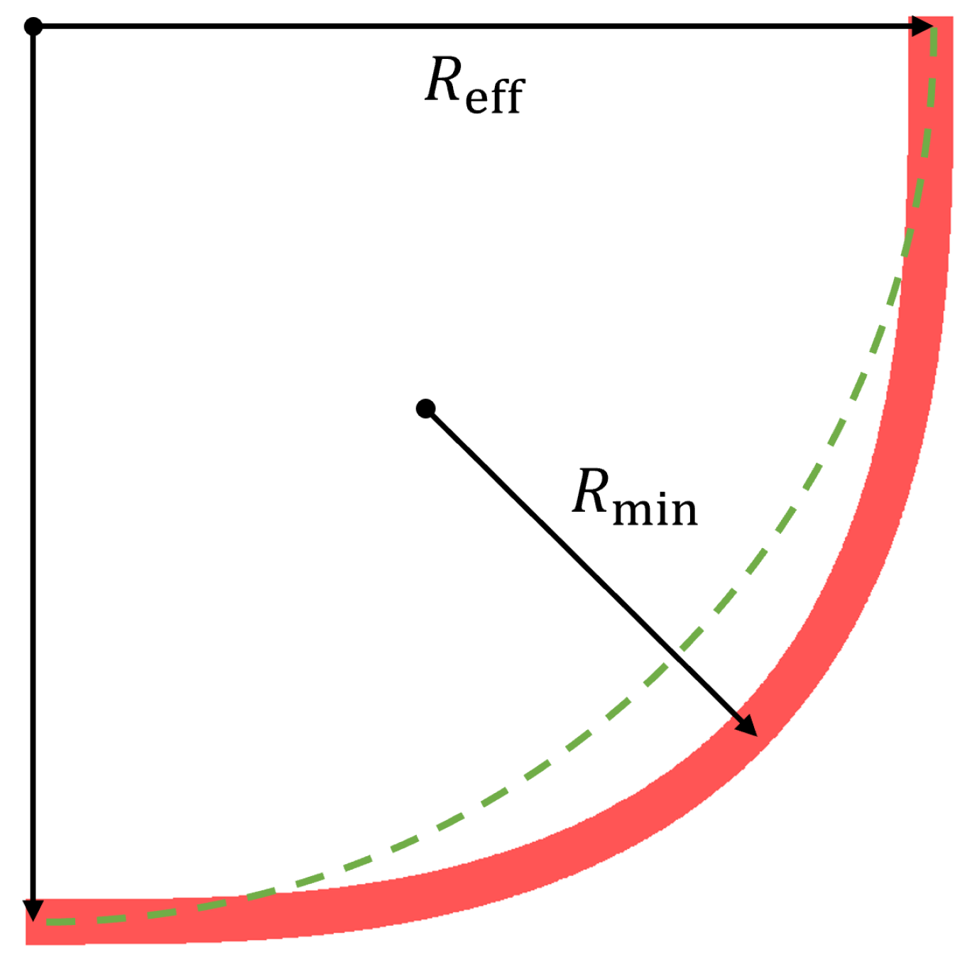
2.3. Mode Crosstalk in Euler Bends

In addition to tapers, bends are another crucial component in the design of PIC devices. They are commonly used to alter the direction of light propagation, diminish device footprint, and interconnect photonic elements. Besides linear transmission losses, bending losses also include radiative losses arising from a bending mode and polarization-related losses induced by mode crosstalk. To address the issue of bending losses, various bend geometries have been proposed [34], with one of the most popular bends being based on Euler spirals. Euler bends avoid mode coupling to unwanted higher-order modes and reduce radiative losses by linearly increasing the bend curvature along its path length [56]. Nevertheless, even with Euler bends, slanted etching angles still cause crosstalk issues.
Figure 6 delineates a “Euler L-bend” composed of two symmetric 45° Euler spirals [57], which was studied in our simulation. Let α be the turning angle measured from the effective center. When 0 < α π 4 , the trajectory equation is written as
x ( α ) = R eff · 0 α cos ( t 2 ) d t 0 π 4 [ cos ( t 2 ) + sin ( t 2 ) ] d t y ( α ) = R eff · 0 α sin ( t 2 ) d t 0 π 4 [ cos ( t 2 ) + sin ( t 2 ) ] d t
where R eff is defined as the effective radius of the Euler bend. The minimum radius of curvature turns out at the 45 position. The green dashed line demonstrates a comparison with an arc with the same R eff .
Similar to the taper simulations, we attempted to isolate the effects of geometrical and index asymmetry by fully etching thin film LiNbO3, cladded with SiO2. We studied the polarization fraction evolution and mode transmittance after the beam propagates through the 90° Euler bend in x-cut LNOI, because mode crosstalk becomes almost inevitable in x-cut LNOI where the index ellipsoid inside the transverse cross section varies as the waveguide turns. An example where the 780 nm TE00 mode propagates through a Euler bend with R eff = 28 μm is given in Figure 7, with TW = 1.5 μm. When θ = 70 , there exists a mixture of the 6.4% TM polarization component in the output port, as shown in Figure 7a. Figure 7b then gives the mode spectrum in the output port, indicating significant polarization-related losses as 9.7% of the input TE00 mode was converted into higher-order modes. Both polarization fidelity and input mode transmittance were improved with vertical etching, as can be concluded from Figure 7c,d, which implies only a mild deformation of the TE00 field profile in the output port. We then modeled the Euler bend structure in Figure 6 with a different R eff . The results of 780 nm and 1550 nm TE00 mode propagation are plotted in Figure 8.

3. Demonstration of Vertical Etching

Besides the simulation, we further examined the feasibility of vertical etching by introducing an innovative two-step dry etching technology. To date, numerous fabrication technique advancements have greatly propelled the development of LNOI photonics [58], including dry etching [59,60,61,62], wet etching [63,64], and focused ion beam (FIB) etching techniques [65,66]. Among these techniques, dry etching stands out due to its simplicity and intricacy in fabrication, and compatibility with CMOS processes. The traditional dry etching process involves creating an etching mask on the LNOI surface with high selectivity to LiNbO3. Subsequently, reactive ion etching, Ar ion milling, or another etching method is employed to etch the LNOI, and finally, the etching mask is removed to produce a rib or ridge waveguide. Despite its advantages of fabricating smooth waveguides with low propagation losses, sloping sidewalls commonly occur due to the resistance of LiNbO3 to etching and the excessive generation of byproducts. As etching progresses, these byproducts adhere to the sidewalls, forming a barrier and resulting in a slope.
In our fabrication, the waveguide was patterned using electron beam lithography (EBL) followed by fabrication with an Ar ion milling process [67]. We employed a distinctive method that alternates vertical incidence with inclined incidence in order to achieve vertical sidewalls. By using the inclined plasma incidence, we effectively thinned the sidewall deposits, which improved the verticality of the sidewalls. However, this approach also tended to a notable reduction in etching selectivity. Given the two-step etching process we utilized, a thicker mask was necessary to withstand the additional etching step. We, therefore, meticulously controlled the mask thickness during the experiments, as adequate masking is crucial for maintaining smooth and vertical sidewalls. Throughout the fabrication process, we fine-tuned the etching parameters to achieve optimal results, ultimately producing a waveguide sample with nearly vertical sidewalls. As depicted in Figure 9, we fabricated a waveguide with a 600 nm film TK and an ED of 300 nm. We performed cross-sectional SEM characterization, which revealed the actual sidewall angles of 88.8° and 89.4°, confirming the feasibility of nearly vertical etching. A group of waveguides whose TWs = 1.2 μm were fabricated, and the average transmission loss was measured to be 0.69 dB/cm referring to the method in Ref. [8], which is comparable to the conventional waveguide with slanted sidewalls of the same top width. This demonstration, though not fully etched through, underscores the potential of our two-step etching technique for achieving vertical sidewalls.

4. Discussion

Unlike traditional approaches that attempt to avoid crosstalk by selecting specific waveguide configurations, we emphasize the importance of vertical etching to effectively mitigate mode hybridization and crosstalk. Throughout our simulation, the 70 angle represented the standard base angle achieved with advanced dry etching techniques, whereas the 90 angle denoted vertical etching. We first quantified the impact of etching angles on mode hybridization in Section 2.1. When the TW reached a critical value at a fixed ED, two orthogonally polarized modes intersected at their effective refractive indices ( n eff ) [26]. Hybridization was exacerbated when a large field was tightly confined in a relatively small waveguide cross section even in fully symmetric configurations, as shown in Figure 1e,h. According to Ref. [18], mode hybridization persists when two modes share the same n eff even in the vertically fully etched-through cases. The reason for the absence of observable mode hybridization in Figure 1f,g is that the TW scanning step missed the precise points where the sharp peaks of mode hybridization were theoretically located. Those “exact structures” are almost non-existent in practice because it is highly improbable for fabricated waveguides to precisely match these configurations. Moreover, fabrication inaccuracies and manufacturing tolerances lead to random deviations from the theoretical design, further reducing the likelihood of encountering these exact structures. These simulations provide insights into how vertical sidewalls in common configurations can mitigate polarization-related issues, serving as a foundational step before examining mode crosstalk in specific components like tapers and bends.
We took the fully etched-through adiabatic tapers and symmetric Euler bends as examples to discuss the amendment of input polarization purity and mode transmittance with vertical sidewalls. In Section 2.2, we characterized mode crosstalk in a tapered waveguide whose TW passes through the hybridization “strips” in Figure 1c–e (the red dashed lines). In Figure 3, Figure 4 and Figure 5, two complimentary criteria provide a complete insight into the taper performance in terms of polarization and mode fidelity. We can conclude that mode crosstalk intensified when the taper provided ample space for highly hybridized modes to evolve, as shown in Figure 3a–c. This substantial enhancement demonstrates the critical role of vertical etching in maintaining mode fidelity and polarization purity, particularly for long-wavelength TM modes in z-cut LNOI waveguides. Our results indicate that vertical etching significantly improves taper performance by reducing mode crosstalk in z-cut LNOI tapered waveguides, particularly for long-wavelength TM modes. These findings highlight the critical role of vertical etching in minimizing polarization-related losses and maintaining mode fidelity.
We then studied the polarization fraction evolution and mode transmittance after the beam propagated through the 90° Euler bend in x-cut LNOI in Section 2.3. As the modal field continuously changed during bending, larger bending radii and critical TWs were often required to depress mode crosstalk. The comparison between the 1550 nm and 780 nm lines plotted in Figure 8 tells us that mode crosstalk at shorter wavelengths is more severe under the same R eff . This observation is consistent with the physical essence of mode crosstalk, because bends with the same TW and curvature can accommodate more modes and are, therefore, prone to crosstalk. Subsequently, the reduction in polarization-related losses via vertical etching is more pronounced at short wavelengths. Therefore, we can further expect that high polarization and mode fidelity can be achieved for higher-order mode propagation. When we focused on the same wavelength, slanted sidewalls exhibited inferior performance compared to vertical sidewalls. Vertical etching could offset the adverse effects of reduced R eff on mode crosstalk. For example, the 1550 nm TE00 mode transmittance of R eff = 13 μm fabricated by vertical etching even transcended that of R eff = 50 μm when θ = 70 . As a consequence, vertical etching exhibited superior performance over traditional slanted sidewalls in the same bending structure for both short and long wavelength modes, because it maximizes geometrical symmetry, thereby reducing mode hybridization and crosstalk. Practically, vertical etching helps reduce polarization-related losses and minimize device footprint.
To demonstrate the fabrication feasibility, we innovatively proposed a two-step etching technique in Section 3. After alternating steps of conventional etching with the vertical plasma incidence and inclined plasma incidence, we achieved a 300 nm ED with nearly vertical sidewalls on a 600 nm thick thin film (Figure 9). This advancement lays a solid foundation for future innovations in LNOI platforms, promising substantial improvements in device performance.

5. Conclusions

In conclusion, we studied and compared mode hybridization and polarization-related mode crosstalk in various LNOI devices with slanted sidewalls of 70° and vertical sidewalls. The simulation results show that mode hybridization can be adequately mitigated via vertical etching due to the improved geometrical symmetry. Mode crosstalk becomes considerably exacerbated only when the device component offers ample space for highly hybrid modes to overlap and evolve with each other. In a practical sense, polarization-related losses (conversion to other modes) in tapers and bends can be sufficiently inhibited, and the adverse effects on mode crosstalk from downsizing the bend can be compensated for in both short and long wavelengths. As a demonstration of fabrication feasibility, we innovatively proposed a two-step etching technique, yielding a 300 nm ED with nearly vertical sidewalls on a 600 nm thick thin film. Such vertical etching waveguides pave the way for highly compact and efficient photonic devices. In the future, this innovation holds considerable promise for advancing the capabilities of LNOI platforms. The potential for reduced losses and increased device compactness will undoubtedly drive further innovations, not only in academic research but also in industrial applications, leading to breakthroughs in high-speed modulators, nonlinear optics, and other cutting-edge technologies.

Author Contributions

Conceptualization, C.W., Y.L., M.C., X.-H.T. and H.-Y.L.; methodology, C.W., Y.L., J.Q., Z.Y. (Zhilin Ye), D.G., M.C., X.-H.T. and H.-Y.L.; software, C.W., Y.L. and D.G.; validation, Z.Y. (Zhijun Yin), X.-H.T., H.-Y.L., S.-N.Z. and Z.X.; formal analysis, C.W. and Y.L.; investigation, C.W., Y.L., J.Q., Z.Y. (Zhilin Ye), M.C. and X.-H.T.; resources, Z.Y. (Zhijun Yin), X.-H.T., H.-Y.L., S.-N.Z. and Z.X.; data curation, C.W., Y.L. and D.G.; writing—original draft preparation, C.W., Y.L. and Z.Y. (Zhilin Ye); writing—review and editing, X.-H.T., H.-Y.L. and Z.X.; visualization, C.W., J.Q. and Z.Y. (Zhilin Ye); supervision, X.-H.T., H.-Y.L., S.-N.Z. and Z.X.; project administration, X.-H.T., H.-Y.L., S.-N.Z. and Z.X.; funding acquisition, X.-H.T., H.-Y.L., S.-N.Z. and Z.X. All authors have read and agreed to the published version of the manuscript.

Funding

This work was supported by the National Natural Science Foundation of China (62293523, 62305156), National Key R&D Program of China (2022YFA1205100, 2019YFA0705000), Jiangsu Natural Science Foundation (BK20232033), Zhangjiang Laboratory (ZJSP21A001), the National Postdoctoral Program for Innovative Talents (BX2021122), Jiangsu Funding Program for Excellent Postdoctoral Talent, and China Postdoctoral Science Foundation (No. 2022M711570).

Institutional Review Board Statement

Not applicable.

Informed Consent Statement

Not applicable.

Data Availability Statement

The data presented in this study are available on request from the corresponding authors. The data are not publicly available because they are part of an ongoing study.

Conflicts of Interest

Authors Jingyuan Qiu, Zhilin Ye and Zhijun Yin are employed by the company NanZhi Institute of Advanced Optoelectronic Integration Technology Co., Ltd. The remaining authors declare that the research was conducted in the absence of any commercial or financial relationships that could be construed as a potential conflict of interest.

Abbreviations

The following abbreviations are used in this manuscript:
BOXBuried oxide
EBLElectron beam lithography
EDEtching depth
EOElectro-optic
LNOILithium niobate-on-insulator
qTEQuasi-transverse electric
qTMQuasi-transverse magnetic
SEMScanning Electron Microscope
TKThickness
TWTop width

References

  1. Chiles, J.; Fathpour, S. Silicon photonics beyond silicon-on-insulator. J. Opt. 2017, 19, 053001. [Google Scholar] [CrossRef]
  2. Chen, G.; Li, N.; Ng, J.D.; Lin, H.L.; Zhou, Y.; Fu, Y.H.; Lee, L.Y.T.; Yu, Y.; Liu, A.Q.; Danner, A.J. Advances in lithium niobate photonics: Development status and perspectives. Adv. Photonics 2022, 4, 034003. [Google Scholar] [CrossRef]
  3. Saravi, S.; Pertsch, T.; Setzpfandt, F. Lithium niobate on insulator: An emerging platform for integrated quantum photonics. Adv. Opt. Mater. 2021, 9, 2100789. [Google Scholar] [CrossRef]
  4. Zhu, D.; Shao, L.; Yu, M.; Cheng, R.; Desiatov, B.; Xin, C.; Hu, Y.; Holzgrafe, J.; Ghosh, S.; Shams-Ansari, A.; et al. Integrated photonics on thin-film lithium niobate. Adv. Opt. Photonics 2021, 13, 242–352. [Google Scholar] [CrossRef]
  5. Yuan, S.; Hu, C.; Pan, A.; Ding, Y.; Wang, X.; Qu, Z.; Wei, J.; Liu, Y.; Zeng, C.; Xia, J. Photonic devices based on thin-film lithium niobate on insulator. J. Semicond. 2021, 42, 041304. [Google Scholar] [CrossRef]
  6. You, B.; Yuan, S.; Tian, Y.; Zhang, H.; Zhu, X.; Mortensen, N.A.; Cheng, Y. Lithium niobate on insulator–fundamental opto-electronic properties and photonic device prospects. Nanophotonics 2024, 13, 3037–3057. [Google Scholar] [CrossRef]
  7. Kaufmann, F. Optimised Nanolithography and Etching of Lithium Niobate on Insulator for Photonic Integrated Circuits. Ph.D. Thesis, ETH Zurich, Zurich, Switzerland, 2023. [Google Scholar]
  8. Zhang, M.; Wang, C.; Cheng, R.; Shams-Ansari, A.; Lončar, M. Monolithic ultra-high-Q lithium niobate microring resonator. Optica 2017, 4, 1536–1537. [Google Scholar] [CrossRef]
  9. Wang, C.; Zhang, M.; Chen, X.; Bertrand, M.; Shams-Ansari, A.; Chandrasekhar, S.; Winzer, P.; Lončar, M. Integrated lithium niobate electro-optic modulators operating at CMOS-compatible voltages. Nature 2018, 562, 101–104. [Google Scholar] [CrossRef]
  10. Shao, L.; Yu, M.; Maity, S.; Sinclair, N.; Zheng, L.; Chia, C.; Shams-Ansari, A.; Wang, C.; Zhang, M.; Lai, K.; et al. Microwave-to-optical conversion using lithium niobate thin-film acoustic resonators. Optica 2019, 6, 1498–1505. [Google Scholar] [CrossRef]
  11. Xu, M.; He, M.; Zhang, H.; Jian, J.; Pan, Y.; Liu, X.; Chen, L.; Meng, X.; Chen, H.; Li, Z.; et al. High-performance coherent optical modulators based on thin-film lithium niobate platform. Nat. Commun. 2020, 11, 3911. [Google Scholar] [CrossRef]
  12. Wan, L.; Yang, Z.; Zhou, W.; Wen, M.; Feng, T.; Zeng, S.; Liu, D.; Li, H.; Pan, J.; Zhu, N.; et al. Highly efficient acousto-optic modulation using nonsuspended thin-film lithium niobate-chalcogenide hybrid waveguides. Light Sci. Appl. 2022, 11, 145. [Google Scholar] [CrossRef]
  13. Vazimali, M.G.; Fathpour, S. Applications of thin-film lithium niobate in nonlinear integrated photonics. Adv. Photonics 2022, 4, 034001. [Google Scholar] [CrossRef]
  14. McKenna, T.P.; Stokowski, H.S.; Ansari, V.; Mishra, J.; Jankowski, M.; Sarabalis, C.J.; Herrmann, J.F.; Langrock, C.; Fejer, M.M.; Safavi-Naeini, A.H. Ultra-low-power second-order nonlinear optics on a chip. Nat. Commun. 2022, 13, 4532. [Google Scholar] [CrossRef]
  15. Ling, J.; Staffa, J.; Wang, H.; Shen, B.; Chang, L.; Javid, U.A.; Wu, L.; Yuan, Z.; Lopez-Rios, R.; Li, M.; et al. Self-Injection Locked Frequency Conversion Laser. Laser Photonics Rev. 2023, 17, 2200663. [Google Scholar] [CrossRef]
  16. Ghosh, S.; Mukhopadhyay, B.; Sen, G.; Basu, P. Study of Si-Ge-Sn based heterobipolar phototransistor (HPT) exploiting quantum confined Stark effect and Franz Keldysh effect with and without resonant cavity. Phys. E Low-Dimens. Syst. Nanostruct. 2019, 106, 62–67. [Google Scholar] [CrossRef]
  17. Hsieh, Y.D.; Lin, J.H.; Soref, R.; Sun, G.; Cheng, H.H.; Chang, G.E. Electro-absorption modulation in GeSn alloys for wide-spectrum mid-infrared applications. Commun. Mater. 2021, 2, 40. [Google Scholar] [CrossRef]
  18. Somasiri, N.; Rahman, B.A. Polarization crosstalk in high index contrast planar silica waveguides with slanted sidewalls. J. Light. Technol. 2003, 21, 54. [Google Scholar] [CrossRef]
  19. Kaushalram, A.; Hegde, G.; Talabattula, S. Mode hybridization analysis in thin film lithium niobate strip multimode waveguides. Sci. Rep. 2020, 10, 16692. [Google Scholar] [CrossRef]
  20. Dai, D. Advanced passive silicon photonic devices with asymmetric waveguide structures. Proc. IEEE 2018, 106, 2117–2143. [Google Scholar] [CrossRef]
  21. Guo, J.; Zhao, Y. Analysis of mode hybridization in tapered waveguides. IEEE Photonics Technol. Lett. 2015, 27, 2441–2444. [Google Scholar] [CrossRef]
  22. Sakai, A.; Fukazawa, T.; Baba, T. Estimation of polarization crosstalk at a micro-bend in Si-photonic wire waveguide. J. Light. Technol. 2004, 22, 520–525. [Google Scholar] [CrossRef]
  23. Pan, A.; Hu, C.; Zeng, C.; Xia, J. Fundamental mode hybridization in a thin film lithium niobate ridge waveguide. Opt. Express 2019, 27, 35659–35669. [Google Scholar] [CrossRef]
  24. Dai, D.; Bowers, J.E. Novel concept for ultracompact polarization splitter-rotator based on silicon nanowires. Opt. Express 2011, 19, 10940–10949. [Google Scholar] [CrossRef]
  25. Chen, D.; Xiao, X.; Wang, L.; Yu, Y.; Liu, W.; Yang, Q. Low-loss and fabrication tolerant silicon mode-order converters based on novel compact tapers. Opt. Express 2015, 23, 11152–11159. [Google Scholar] [CrossRef]
  26. Dai, D.; Zhang, M. Mode hybridization and conversion in silicon-on-insulator nanowires with angled sidewalls. Opt. Express 2015, 23, 32452–32464. [Google Scholar] [CrossRef]
  27. Abu-Elmaaty, B.E.; Shalaby, H.M. Highly efficient silicon mode converter and polarization rotator using a silicon-based hybrid plasmonic waveguide. J. Opt. Soc. Am. B 2023, 40, 2789–2795. [Google Scholar] [CrossRef]
  28. Xie, H.; Liu, Y.; Wang, S.; Wang, Y.; Yao, Y.; Song, Q.; Du, J.; He, Z.; Xu, K. Highly compact and efficient four-mode multiplexer based on pixelated waveguides. IEEE Photonics Technol. Lett. 2020, 32, 166–169. [Google Scholar] [CrossRef]
  29. Han, X.; Jiang, Y.; Frigg, A.; Xiao, H.; Zhang, P.; Nguyen, T.G.; Boes, A.; Yang, J.; Ren, G.; Su, Y.; et al. Mode and polarization-division multiplexing based on silicon nitride loaded lithium niobate on insulator platform. Laser Photonics Rev. 2022, 16, 2100529. [Google Scholar] [CrossRef]
  30. Selvaraja, S.K.; Bogaerts, W.; Van Thourhout, D. Loss reduction in silicon nanophotonic waveguide micro-bends through etch profile improvement. Opt. Commun. 2011, 284, 2141–2144. [Google Scholar] [CrossRef]
  31. Sun, C.; Yu, Y.; Chen, G.; Zhang, X. Ultra-compact bent multimode silicon waveguide with ultralow inter-mode crosstalk. Opt. Lett. 2017, 42, 3004–3007. [Google Scholar] [CrossRef]
  32. Fujisawa, T.; Makino, S.; Sato, T.; Saitoh, K. Low-loss, compact, and fabrication-tolerant Si-wire 90 waveguide bend using clothoid and normal curves for large scale photonic integrated circuits. Opt. Express 2017, 25, 9150–9159. [Google Scholar] [CrossRef]
  33. Jiang, X.; Wu, H.; Dai, D. Low-loss and low-crosstalk multimode waveguide bend on silicon. Opt. Express 2018, 26, 17680–17689. [Google Scholar] [CrossRef] [PubMed]
  34. Vogelbacher, F.; Nevlacsil, S.; Sagmeister, M.; Kraft, J.; Unterrainer, K.; Hainberger, R. Analysis of silicon nitride partial Euler waveguide bends. Opt. Express 2019, 27, 31394–31406. [Google Scholar] [CrossRef] [PubMed]
  35. Jang, K.; Novick, A.; Rizzo, A.; Bergman, K. Universal CMOS-foundry compatible platform for ultra-low loss SOI waveguide bends. In Proceedings of the 2023 Optical Fiber Communications Conference and Exhibition (OFC), San Diego, CA, USA, 5–9 March 2023; pp. 1–3. [Google Scholar]
  36. Zhang, E.; Yang, S.; Zhang, L. General waveguide bend design based on cubic spline interpolation and inverse design. J. Light. Technol. 2024, 42, 4614–4625. [Google Scholar] [CrossRef]
  37. Chamorro-Posada, P. Silicon nitride bent asymmetric coupled waveguides with partial Euler bends. Photonics 2024, 11, 218. [Google Scholar] [CrossRef]
  38. Vermeulen, D.; Van Acoleyen, K.; Ghosh, S.; De Cort, W.; Yebo, N.A.; Hallynck, E.; De Vos, K.; Debackere, P.; Dumon, P.; Bogaerts, W.; et al. Efficient tapering to the fundamental quasi-TM mode in asymmetrical waveguides. In Proceedings of the 15th European Conference on Integrated Optics (ECIO 2010), Cambridge, UK, 7–9 April 2010. [Google Scholar]
  39. Siew, S.Y.; Cheung, E.J.H.; Liang, H.; Bettiol, A.; Toyoda, N.; Alshehri, B.; Dogheche, E.; Danner, A.J. Ultra-low loss ridge waveguides on lithium niobate via argon ion milling and gas clustered ion beam smoothening. Opt. Express 2018, 26, 4421–4430. [Google Scholar] [CrossRef] [PubMed]
  40. Kozlov, A.; Moskalev, D.; Salgaeva, U.; Bulatova, A.; Krishtop, V.; Volyntsev, A.; Syuy, A. Reactive ion etching of x-cut LiNbO3 in an ICP/TCP system for the fabrication of an optical ridge waveguide. Appl. Sci. 2023, 13, 2097. [Google Scholar] [CrossRef]
  41. Zhuang, R.; He, J.; Qi, Y.; Li, Y. High-Q Thin-Film Lithium Niobate Microrings Fabricated with Wet Etching. Adv. Mater. 2023, 35, 2208113. [Google Scholar] [CrossRef]
  42. Chang, G.E.; Chang, S.W.; Chuang, S.L. Theory for n-type doped, tensile-strained Ge–SixGeySn1-x-y quantum-well lasers at telecom wavelength. Opt. Express 2009, 17, 11246–11258. [Google Scholar] [CrossRef]
  43. Ghosh, S.; Bansal, R.; Sun, G.; Soref, R.A.; Cheng, H.H.; Chang, G.E. Design and optimization of GeSn waveguide photodetectors for 2-μm band silicon photonics. Sensors 2022, 22, 3978. [Google Scholar] [CrossRef]
  44. Powers, P.E.; Haus, J.W. Fundamentals of Nonlinear Optics; CRC Press: Boca Raton, FL, USA, 2017. [Google Scholar]
  45. Bakir, B.B.; De Gyves, A.V.; Orobtchouk, R.; Lyan, P.; Porzier, C.; Roman, A.; Fedeli, J.M. Low-loss (<1 dB) and polarization-insensitive edge fiber couplers fabricated on 200-mm silicon-on-insulator wafers. IEEE Photonics Technol. Lett. 2010, 22, 739–741. [Google Scholar]
  46. Hatori, N.; Shimizu, T.; Okano, M.; Ishizaka, M.; Yamamoto, T.; Urino, Y.; Mori, M.; Nakamura, T.; Arakawa, Y. A hybrid integrated light source on a silicon platform using a trident spot-size converter. J. Light. Technol. 2014, 32, 1329–1336. [Google Scholar] [CrossRef]
  47. Krasnokutska, I.; Tambasco, J.L.J.; Peruzzo, A. Nanostructuring of LNOI for efficient edge coupling. Opt. Express 2019, 27, 16578–16585. [Google Scholar] [CrossRef]
  48. Shim, E.; Gil-Molina, A.; Westreich, O.; Dikmelik, Y.; Lascola, K.; Gaeta, A.L.; Lipson, M. Tunable single-mode chip-scale mid-infrared laser. Commun. Phys. 2021, 4, 268. [Google Scholar] [CrossRef]
  49. Mao, D.; Wang, Y.; El-Fiky, E.; Xu, L.; Kumar, A.; Jaques, M.; Samani, A.; Carpentier, O.; Bernal, S.; Alam, M.S.; et al. Adiabatic coupler with design-intended splitting ratio. J. Light. Technol. 2019, 37, 6147–6155. [Google Scholar] [CrossRef]
  50. Nehra, R.; Sekine, R.; Ledezma, L.; Guo, Q.; Gray, R.M.; Roy, A.; Marandi, A. Few-cycle vacuum squeezing in nanophotonics. Science 2022, 377, 1333–1337. [Google Scholar] [CrossRef]
  51. Ledezma, L.; Roy, A.; Costa, L.; Sekine, R.; Gray, R.; Guo, Q.; Nehra, R.; Briggs, R.M.; Marandi, A. Octave-spanning tunable infrared parametric oscillators in nanophotonics. Sci. Adv. 2023, 9, eadf9711. [Google Scholar] [CrossRef]
  52. Wang, J.; Bo, F.; Wan, S.; Li, W.; Gao, F.; Li, J.; Zhang, G.; Xu, J. High-Q lithium niobate microdisk resonators on a chip for efficient electro-optic modulation. Opt. Express 2015, 23, 23072–23078. [Google Scholar] [CrossRef]
  53. Chauvet, M.; Henrot, F.; Bassignot, F.; Devaux, F.; Gauthier-Manuel, L.; Pêcheur, V.; Maillotte, H.; Dahmani, B. High efficiency frequency doubling in fully diced LiNbO3 ridge waveguides on silicon. J. Opt. 2016, 18, 085503. [Google Scholar] [CrossRef]
  54. Wolf, R.; Breunig, I.; Zappe, H.; Buse, K. Cascaded second-order optical nonlinearities in on-chip micro rings. Opt. Express 2017, 25, 29927–29933. [Google Scholar] [CrossRef] [PubMed]
  55. Zafar, H.; Moreira, P.; Taha, A.M.; Paredes, B.; Dahlem, M.S.; Khilo, A. Compact silicon TE-pass polarizer using adiabatically-bent fully-etched waveguides. Opt. Express 2018, 26, 31850–31860. [Google Scholar] [CrossRef]
  56. Cherchi, M.; Ylinen, S.; Harjanne, M.; Kapulainen, M.; Aalto, T. Dramatic size reduction of waveguide bends on a micron-scale silicon photonic platform. Opt. Express 2013, 21, 17814–17823. [Google Scholar] [CrossRef] [PubMed]
  57. Cherchi, M.; Ylinen, S.; Harjanne, M.; Kapulainen, M.; Vehmas, T.; Aalto, T. The Euler bend: Paving the way for high-density integration on micron-scale semiconductor platforms. Silicon Photonics IX SPIE 2014, 8990, 20–26. [Google Scholar]
  58. Lin, J.; Bo, F.; Cheng, Y.; Xu, J. Advances in on-chip photonic devices based on lithium niobate on insulator. Photonics Res. 2020, 8, 1910–1936. [Google Scholar] [CrossRef]
  59. Krasnokutska, I.; Tambasco, J.L.J.; Li, X.; Peruzzo, A. Ultra-low loss photonic circuits in lithium niobate on insulator. Opt. Express 2018, 26, 897–904. [Google Scholar] [CrossRef] [PubMed]
  60. Wang, C.; Burek, M.J.; Lin, Z.; Atikian, H.A.; Venkataraman, V.; Huang, I.C.; Stark, P.; Lončar, M. Integrated high quality factor lithium niobate microdisk resonators. Opt. Express 2014, 22, 30924–30933. [Google Scholar] [CrossRef] [PubMed]
  61. Shen, M.; Yang, L.; Xu, Y.; Tang, H.X. Parasitic conduction loss of lithium niobate on insulator platform. Appl. Phys. Lett. 2024, 124, 101107. [Google Scholar] [CrossRef]
  62. Zhou, J.X.; Gao, R.H.; Lin, J.; Wang, M.; Chu, W.; Li, W.B.; Yin, D.F.; Deng, L.; Fang, Z.W.; Zhang, J.H.; et al. Electro-optically switchable optical true delay lines of meter-scale lengths fabricated on lithium niobate on insulator using photolithography assisted chemo-mechanical etching. Chin. Phys. Lett. 2020, 37, 084201. [Google Scholar] [CrossRef]
  63. Hui, H.; Ricken, R.; Sohler, W. Etching of lithium niobate: From ridge waveguides to photonic crystal structures. In Proceedings of the ECIO’08 Eindhoven, Eindhoven, The Netherlands, 11–13 June 2008. [Google Scholar]
  64. Li, Y.; Lan, T.; Yang, D.; Xiang, M.; Dai, J.; Li, C.; Wang, Z. Research of selective etching in LiNbO3 using proton-exchanged wet etching technique. Mater. Res. Express 2020, 7, 056202. [Google Scholar] [CrossRef]
  65. You, J.; Wu, W.; Jin, C.; Qu, L.; Zhang, D.; Qi, J.; Cai, W.; Ren, M.; Xu, J. Raman characterization of focused ion beam fabricated lithium niobate film. J. Appl. Phys. 2024, 135, 033101. [Google Scholar] [CrossRef]
  66. Si, G.; Danner, A.J.; Teo, S.L.; Teo, E.J.; Teng, J.; Bettiol, A.A. Photonic crystal structures with ultrahigh aspect ratio in lithium niobate fabricated by focused ion beam milling. J. Vac. Sci. Technol. B 2011, 29, 021205. [Google Scholar] [CrossRef]
  67. NanZhi Institute of Advanced Optoelectronic Integration Technology Co., Ltd.—Product Development—Technical Services. Available online: https://www.citedrive.com/overleaf (accessed on 4 August 2024).
Figure 1. Schematics and simulation results for mode hybridization in rib waveguides with varying etching depths (EDs) and top widths (TWs). (a) The rib waveguide profile in our simulation. Thickness (TK) = 600 n m with a varied ED. The upper strip is an isosceles trapezoid, whose TW and base angle ( θ ) are defined. (b) When ED = TK and θ = 90 , the rib waveguide degrades into a strip waveguide with a rectangular profile. (ch) γ TE or γ TM maps when scanning TW and ED. The dark strips indicate severe mode hybridization. (c,f) γ TE maps for the 780 nm TE00 mode in the x-cut LNOI waveguide where (c) θ = 70 and (f) θ = 90 , respectively. (d,g) γ TM maps for the 780 nm TM00 mode in the z-cut LNOI waveguide where (d) θ = 70 and (g) θ = 90 , respectively. (e,h) γ TM maps for the 1550 nm TM00 mode in the z-cut LNOI waveguide where (e) θ = 70 and (h) θ = 90 , respectively.
Photonics 11 00771 g001
Figure 2. Schematic diagram of the taper in the simulation. The LiNbO3 waveguide is surrounded by SiO2 cladding, forming a buried channel waveguide. (a) The side view of the input side shows a 600 nm thick fully etched-through waveguide. TW = 5 μm, and the base angle θ varied in the simulation. (b) The top view shows that the top width is linearly tapered from 5 μm to 1.3 μm in a 500 μm propagating distance. (c) A 3D model of the taper. The beam propagates from the wide side to the narrow side. The coordinate axes indicate the polarization and propagation direction for calculation, which is not consistent with the LiNbO3 crystal orientation.
Photonics 11 00771 g002
Figure 3. Simulation results of the 1550 nm TM00 mode propagating through the z-cut LNOI tapered waveguide. (a,d) y profile of the input TM00 mode propagating in the taper with base angles (a) 70 and (d) 90 . (b,e) Evolution of γ TE and γ TM from the input TM00 mode to the output field profile where (b) θ = 70 and (e) θ = 90 . (c,f) Mode components of the output field profile where (c) θ = 70 and (f) θ = 90 .
Photonics 11 00771 g003
Figure 4. Simulation results of the 780 nm TM00 mode propagating through the z-cut LNOI tapered waveguide. (a,d) y profile of the input TM00 mode propagating in the taper with base angles (a) 70 and (d) 90 . (b,e) Evolution of γ TE and γ TM from the input TM00 mode to the output field profile where (b) θ = 70 and (e) θ = 90 . (c,f) Mode components of the output field profile where (c) θ = 70 and (f) θ = 90 .
Photonics 11 00771 g004
Figure 5. Simulation results of the 780 nm TE00 mode propagating through the x-cut LNOI tapered waveguide. (a,d) y profile of the input TE00 mode propagating in the taper with base angles (a) 70 and (d) 90 . (b,e) Evolution of γ TE and γ TM from the input TE00 mode to the output field profile where (b) θ = 70 and (e) θ = 90 . (c,f) Mode components of the output field profile where (c) θ = 70 and (f) θ = 90 .
Photonics 11 00771 g005
Figure 6. Schematic diagram of a 90 Euler bend. The thick red solid line represents a 45 -to- 45 symmetric Euler bend curve, while the thin green dashed line compares it with an arc of the same effective radius R eff . The minimum radius of curvature, R min , turns out at the 45 position.
Photonics 11 00771 g006
Figure 7. Simulation results of 780 nm TE00 mode propagating through the x-cut LNOI 90° Euler bend composed of two symmetric 45° Euler curves, where R eff = 28 μm and TW = 1.5 μm. (a,c) Evolution of γ TE and γ TM from the input TE00 mode to the output field profile where (a) θ = 70 and (c) θ = 90 . (b,d) Mode components of the output field profile where (b) θ = 70 and (d) θ = 90 .
Photonics 11 00771 g007aPhotonics 11 00771 g007b
Figure 8. TE00 transmission after propagating through a 90 Euler bend with a TW of 1.5 μm versus R eff . Simulated waveguide constructions with base angles 70 (dashed) and 90 (solid) are shown for input TE00 modes with wavelengths of 780 n m (blue) and 1550 n m (orange).
Photonics 11 00771 g008
Figure 9. SEM images of the waveguide facet fabricated by the two-step vertical etching. The (left) figure shows that a 300 nm etching depth was achieved on the x-cut 600 nm thick LiNbO3 to form a rib waveguide. In the zoomed-in image (right), the sidewall angles are nearly vertical.
Photonics 11 00771 g009
Disclaimer/Publisher’s Note: The statements, opinions and data contained in all publications are solely those of the individual author(s) and contributor(s) and not of MDPI and/or the editor(s). MDPI and/or the editor(s) disclaim responsibility for any injury to people or property resulting from any ideas, methods, instructions or products referred to in the content.

