Article

The Effect of Lens Focal Length on the Output Characteristics of 1.55 μm Tunable External-Cavity Semiconductor Lasers

Key Laboratory of Laser Technology and Optoelectronic Functional Materials of Hainan Province, Academician Team Innovation Center of Hainan Province, Hainan International Joint Research Center for Semiconductor Lasers, College of Physics and Electronic Engineering, Hainan Normal University, Haikou 571158, China
*
Author to whom correspondence should be addressed.
Photonics 2024, 11(9), 809; https://doi.org/10.3390/photonics11090809
Submission received: 31 July 2024 / Revised: 22 August 2024 / Accepted: 27 August 2024 / Published: 29 August 2024

Abstract

:
The 1.55 μm TECSL has excellent characteristics such as wide tuning, narrow linewidth, high SMSR, and high output power and has a wide range of applications in optical communications, spectral sensing, gas detection, atomic physics, and biomedicine. For the TECSL, the choice of collimating lens is very significant. In order to obtain a wider tuning range, five structures are constructed in this paper to investigate the effect of lens focal length on the output characteristics of 1.55 μm TECSL. It is shown that when the lens focal length is 4.51 mm, the minimum threshold current is 52 mA, the maximum output power is 42.36 mW, the maximum SMSR is 62.15 dB, the narrowest linewidth is 0.26 nm, and 152.3 nm (1458.2~1610.5 nm) can be tuned continuously. It is shown that different lens focal lengths affect the output characteristics of the TECSL, and the performance of the TECSL can be improved by appropriately changing the lens focal length.

1. Introduction

The tunable external-cavity semiconductor laser (TECSL) extends the effective length of the resonant cavity and narrows the linewidth of the laser to the order of kilohertz or even sub-kilohertz through the introduction of external optics [1,2,3], including collimating lenses, diffraction gratings, mirrors, filters, beamsplitters, and other optical components [4,5,6]. The use of external optical components can also change the output wavelength of the laser, realizing a wavelength tuning range of tens or even hundreds of nanometers [7,8,9,10]. The TECSL has excellent properties such as wide tuning, narrow linewidth, high side-mode suppression ratio (SMSR), high output power, etc. The 1.55 μm band TECSL is small, lightweight, and easy to couple with optical fibers [11], which is an indispensable and important component in many fields and is widely used in optical communications [12,13,14], gas detection [15,16], atomic physics [17,18], biomedicine [19,20], and other fields.
For the Littrow-type TECSL, this mainly includes the design and selection of gain chips, collimating lenses, and diffraction gratings in order to obtain a wider tuning range. In recent years, a miniaturized MEMS Littrow tunable laser was investigated by H. Cai et al. The laser uses a collimating lens with a focal length of 0.4 mm and can be continuously tuned to 48.3 nm [21]. Yan Wang et al. investigated the effect of filters on the output characteristics of TECSLs using a collimated lens with a focal length of 1.14 mm, and the continuous tuning of 89 nm was achieved at a current of 200 mA without filters [22]. Shayne Bennetts et al. investigated the performance of TECSLs with different structures using a collimated lens with a focal length of 2.97 mm, and the maximum tuning range was up to 200 nm under a driving current of 340 mA [23]. In addition to this, Feng Gao et al. investigated the effect of small surface coatings on the performance of an InAs/InP quantum dot TECSL. The tuning range of the laser was extended from 39 nm to 104 nm by adding the small-face coating [24]. In the same year, the team found that a high AsH3 flux could effectively increase the optical gain in the low-energy state during the interruption of the quantum dots after their deposition, thus broadening the tuning range of the laser and lowering the threshold current, and in combination with the small-face coating, the tuning range was extended to 140.4 nm [25]. Yan Wang et al. studied three different structures to investigate the relationship between grating properties and SMSR, and the maximum tuning range was 209.9 nm. It was found that the laser performance could be improved by appropriately increasing the number of grating slots and the first-order diffraction efficiency [26]. Huihong Yuan et al. investigated the InAs/InP quantum dot TECSLs, and by combining the high modal gains of the quantum dot materials with the small-faced coatings, the single-mode tuning range was increased to 232 nm [27]. It is easy to discern that the gain chip, lens focal length, grating line number, and grating diffraction efficiency all affect the output characteristics of TECSLs.
In this paper, we demonstrate a commercial InP gain chip Littrow-type TECSL based on a laser with a wide tuning range and high SMSR in the 1.55 μm band. We selected aspherical lenses with focal lengths of 2.97 mm, 3.10 mm, 4.51 mm, 5.50 mm, and 6.20 mm as the collimating lenses for the TECSL, constructed the outer cavity structures of the lenses with five different focal lengths, and systematically investigated the effect of the focal lengths of the lenses on the output characteristics of TECSLs for the first time. It was found that 152.3 nm (1458.2~1610.5 nm) could be tuned continuously when the focal length of the lens was 4.51 mm and the injection current was 200 mA, and there was almost no mode-hopping phenomenon during the tuning process. The maximum SMSR was up to 62.15 dB, the minimum threshold current was 52 mA, the narrowest linewidth was 0.26 nm, and a maximum output power of 42.36 mW was achieved.

2. TECSL Basic Principles

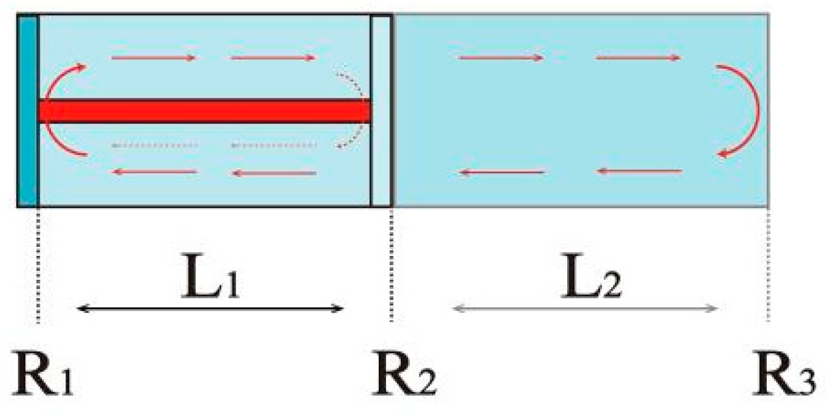
2.1. TECSL Basic Structure

A TECSL can be divided into two main parts, the inner cavity part with active gain and the outer cavity part with passive feedback, as shown in Figure 1.
Here, R1 and R2 are the reflectances of both sides of the inner cavity, R3 is the reflectance of the right side of the outer cavity, L1 is the length of the inner cavity, and L2 is the length of the outer cavity. The inner cavity is generally a gain chip, which is used to provide optical gain. The outer cavity is a variety of optical components such as lenses, diffraction gratings, mirrors, filters, etc., which are used to optimize the device’s performance.

2.2. TECSL Tuning Principle

The TECSL tuning principle is shown in Figure 2. The gain chip emits fluorescence, which is diffracted after passing through a collimating lens and incident on optical elements such as diffraction gratings. After diffraction, part of the diffracted light, i.e., the first-level diffracted light, returns along the optical path to oscillate in the gain chip, and its propagation direction is opposite to the incident direction. This reduces the loss of specific wavelengths in the active region of the gain chip and changes the output mode of the laser. The other part of the diffracted light, i.e., the zero-level diffracted light, is used as the output light. Since only the beam that meets certain conditions can be fed back, the Littrow-type external cavity structure can effectively narrow the linewidth of the laser and increase the SMSR. Not only that, but by adjusting the angle of the diffraction grating, the angle of incidence of the light is changed, which changes the wavelength of the feedback light, thus realizing the tuning of the wavelength.

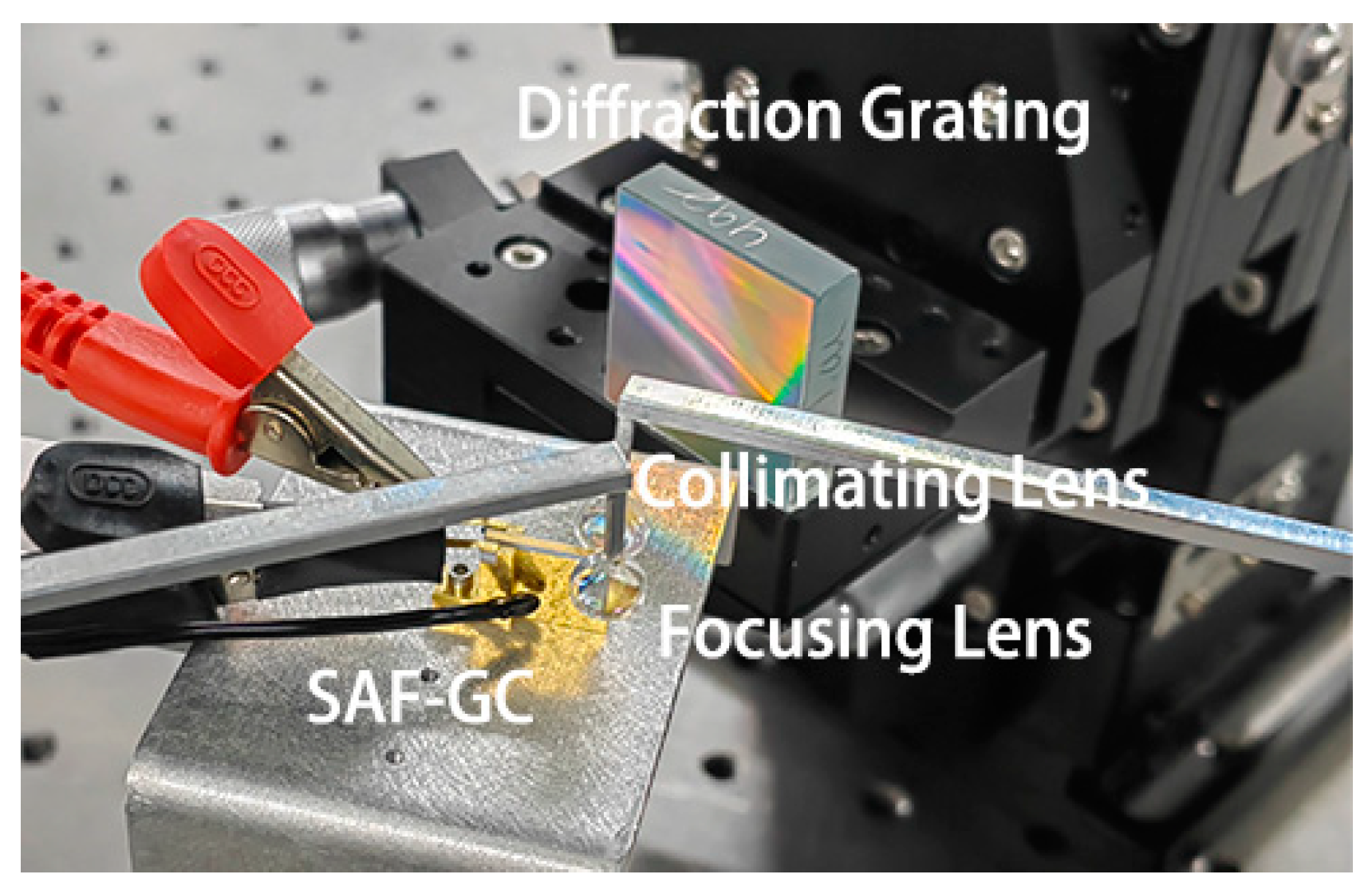
3. TECSL Experimental Setup

The TECSL experimental setup is shown in Figure 3, which mainly consists of a gain chip, a collimating lens, and a diffraction grating, with an outer cavity length of about 45 mm. The TECSL device selection is the most important part of designing the whole TECSL, and choosing the right optics can lead to a great improvement in the optical performance of the laser.
For the selection of the gain chip, the reflectance, center wavelength, and spectral width of the front and rear cavity surfaces need to be considered. The reflectivity of the front and rear cavities determines the output power of the TECSL, and the center wavelength and spectral width determine the output wavelength and tuning range of the TECSL. In order to obtain a wider tuning range, we chose a commercial single-angle-face gain chip (SAF-GC), model SAF1126H from Thorlabs, U.S.A. The SAF-GC has an ultra-low reflectivity (AR < 0.01%) on the front cavity surface, which eliminates virtually all back-reflections and removes the harmful optical feedback that back-reflections create in the laser cavity. The rear cavity surface has a reflectivity of 10%, which maximizes the output power of the laser while ensuring sufficient optical feedback. The gain spectral width exceeds 170 nm, allowing for wide wavelength tuning. The TCM digital temperature control module was used to control the SAF-GC temperature to keep it at 20 °C. For the selection of the diffraction grating, the number of grating lines and the diffraction efficiency need to be considered. The number of grating lines and the diffraction efficiency determine the output characteristics of the TECSL, including the tuning range, output power, and threshold current. A reflective inscribed diffraction grating of 600 lines/mm was selected as the tuning element, and the diffraction efficiency was about 90% at 1.55 μm.
Since the output light of the SAF-GC is highly divergent, collimating optics are required. The selection of the collimating lens is also very important because the collimating lens affects the area illuminated onto the grating and also the size of the focusing point coupled into the SAF-GC. The collimating lens needs to be selected by considering the numerical aperture (NA) of the gain chip, the NA of the collimating lens, and the desired spot diameter. The NA of the collimating lens needs to be larger than the NA of the gain chip, and a lens whose NA is twice the NA of the gain chip can generally be selected. Aspherical lenses with focal lengths of 2.97 mm, 3.10 mm, 4.51 mm, 5.50 mm, and 6.20 mm were selected as the collimating lenses for TECSLs according to the theory combined with the Zemax simulation, and the divergence angle of the beam after collimation was less than 3 mrad.
A comparison of the spot before and after the resonance of the 1.55 μm TECSL is shown in Figure 4 with the injection current of the SAF-GC set to 200 mA. It is easy to see that the spot of the output beam of the TECSL has an elliptical distribution, and after the resonance occurs, the intensity of the spot becomes higher, which leads to the larger diameter of the spot observed on the IR color rendering card.

4. TECSL Test Results and Analysis

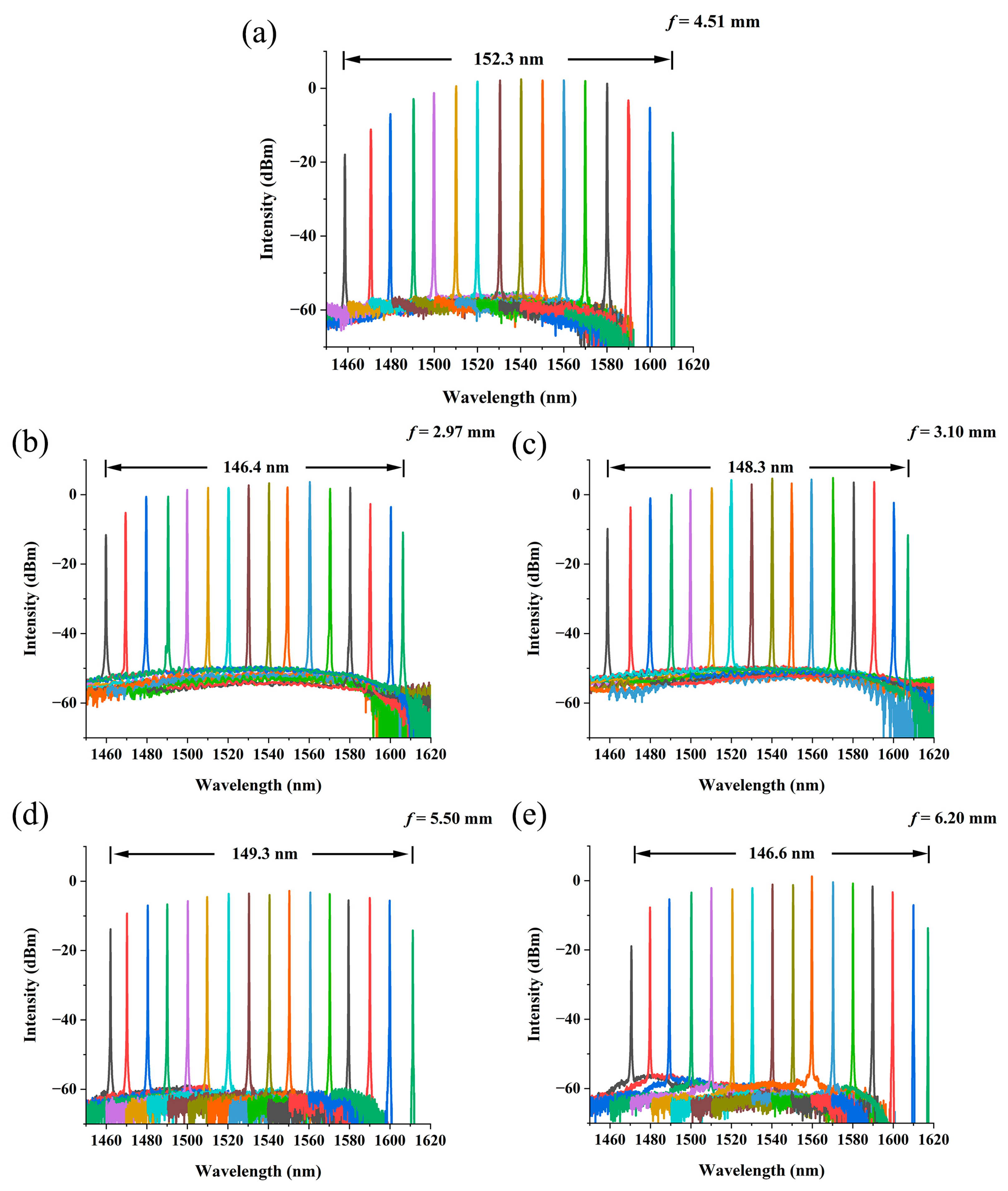
4.1. Effect of Lens Focal Length on TECSL Tuning Range

The tuning ranges of a TECSL with different lens focal lengths at a 200 mA injection current are shown in Figure 5. When the lens focal length is 2.97 mm, the TECSL has a continuous tunable range of 146.4 nm from 1459.8 nm to 1606.2 nm; when the lens focal length is 3.10 mm, the TECSL has a continuous tunable range of 148.3 nm from 1458.9 nm to 1607.2 nm; when the lens focal length is 4.51 mm, the TECSL has a continuous tunable range of 152.3 nm from 1458.2 nm to 1610.5 nm; when the lens focal length is 5.50 mm, the TECSL has a continuous tunable range of 149.3 nm from 1462.0 nm to 1611.3 nm; and when the lens focal length is 6.20 mm, the TECSL has a continuous tunable range of 146.6 nm from 1470.6 nm to 1617.2 nm.
The test data show that the tuning range of a TECSL increases from 146.4 nm to 152.3 nm and then decreases to 146.6 nm as the focal length of the lens increases, with the overall trend of increasing and then decreasing. When the focal length of the lens is 4.51 mm, the tuning range is the largest, and it can continuously tune 152.3 nm (1458.2~1610.5 nm), which can completely cover the S and C bands in the field of optical communication. In addition to this, we also measured the linewidths of TECSLs with different lens focal lengths. The results show that the TECSL linewidths are all less than 0.65 nm, and the narrowest linewidth is 0.26 nm.

4.2. Effect of Lens Focal Length on Threshold Current

The threshold currents of a TECSL for different lens focal lengths are shown in Figure 6. When the lens focal length is 2.97 mm, the minimum threshold current is 60 mA; when the lens focal length is 3.10 mm, the minimum threshold current is 58 mA; when the lens focal length is 4.51 mm, the minimum threshold current is 52 mA; when the lens focal length is 5.50 mm, the minimum threshold current is 57 mA; and when the lens focal length is 6.20 mm, the minimum threshold current is 67 mA.
The threshold current of a TECSL changes with wavelength due to the optical gain of the SAF-GC active region at different wavelengths and the diffraction efficiency of diffraction grating at different wavelengths. The threshold current reaches the minimum at the center wavelength, and the threshold current of the TECSL gradually increases when the output wavelength is far away from the center wavelength. In the tunable range, the threshold current shows a tendency to decrease first and then increase.
It is not difficult to discern that the threshold current of a TECSL shows a trend of decreasing first and then increasing as the focal length of the lens increases. When the focal length of the lens is 4.51 mm, the threshold current is the smallest, which is 52 mA. Compared with other focal lens lengths, the minimum threshold current is reduced by about 15 mA.

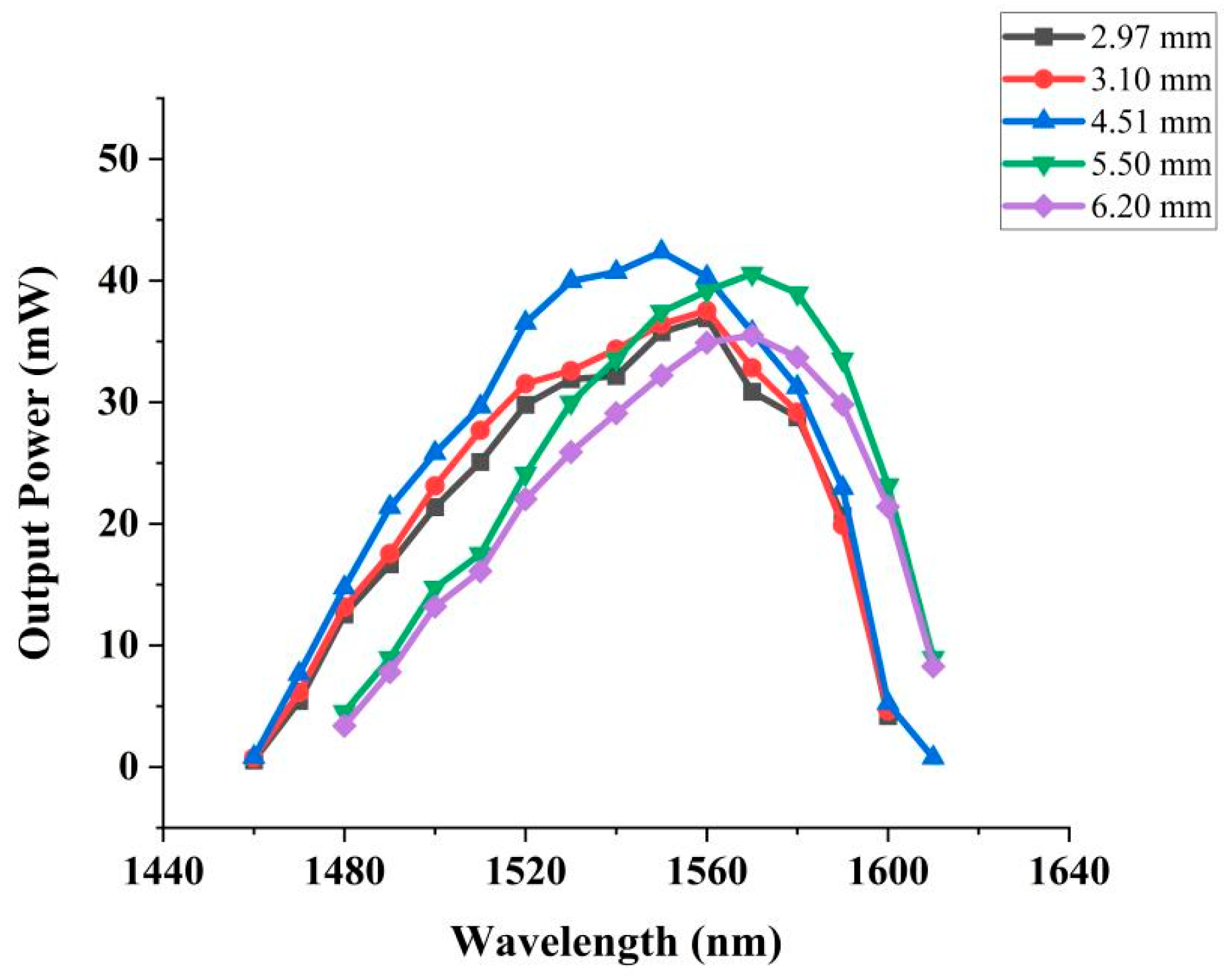
4.3. Effect of Lens Focal Length on Output Power

The output power of a TECSL with different lens focal lengths is shown in Figure 7. When the lens focal length is 2.97 mm, the maximum output power is 36.90 mW; when the lens focal length is 3.10 mm, the maximum output power is 37.53 mW; when the lens focal length is 4.51 mm, the maximum output power is 42.36 mW; when the lens focal length is 5.50 mm, the maximum output power is 40.57 mW; and when the lens focal length is 6.20 mm, the maximum output power is 35.52 mW.
Similar to the threshold current, due to the optical gain of the SAF-GC active region at different wavelengths and the diffraction efficiency of the diffraction grating at different wavelengths, the output power of the TECSL changes with the wavelength and decreases sharply when the wavelength moves in the direction of the short wave or long wave. In the tuning range, the overall tendency is to increase first and then decrease.
The test data show that as the focal length of the lens increases, the output power of the TECSL shows a trend of increasing first and then decreasing. When the focal length of the lens is 4.51 mm, the maximum output power is 42.36 mW. Compared with other focal lens lengths, the maximum output power is increased by about 6.84 mW.

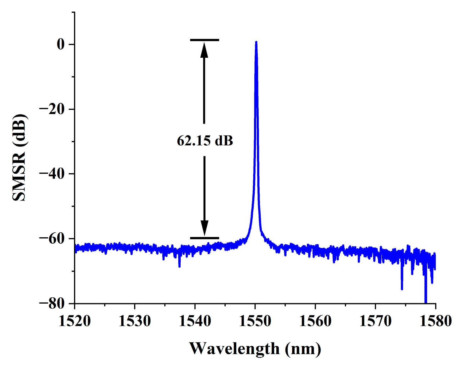
4.4. Effect of Lens Focal Length on SMSR

The SMSR of a TECSL with different lens focal lengths is shown in Figure 8, and the maximum SMSR is shown in Figure 9. When the lens focal length is 2.97 mm, the maximum SMSR is 60.13 dB; when the lens focal length is 3.10 mm, the maximum SMSR is 60.45 dB; when the lens focal length is 4.51 mm, the maximum SMSR is 62.15 dB; when the lens focal length is 5.50 mm, the maximum SMSR is 61.32 dB; and when the lens focal length is 6.20 mm, the maximum SMSR is 59.24 dB.
It is not difficult to see that the SMSR of a TECSL changes with wavelength but is relatively stable in general due to the different optical gains of the SAF-GC active region at different wavelengths and the diffraction efficiencies of the diffraction grating at different wavelengths. When the wavelength approaches the tuning boundary of TECSL, the SMSR decreases rapidly. The test data show that as the focal length of the lens increases, the overall SMSR of the TECSL also shows the same trend of increasing first and then decreasing. When the focal length of the lens is 4.51 mm, the SMSR of the TECSL is generally larger with a maximum of 62.15 dB, and the SMSR away from the center wavelength decreases, but most of them are above 60 dB. Therefore, the TECSL performs best when the lens focal length is 4.51 mm.

5. Conclusions

In this paper, five structures with different lens focal lengths are investigated. It is shown that under the Littrow structure, different lens focal lengths affect the output characteristics of a TECSL, and appropriate changes in lens focal lengths can improve the performance of a TECSL. Within the scope of this study, the output characteristics of the TECSL show a tendency to increase and then decrease with the increase in lens focal length. When the lens focal length is 4.51 mm, the 600 lines/mm TECSL has the best output characteristics, which can be continuously tuned to 152.3 nm (1458.2~1610.5 nm) with a minimum threshold current of 52 mA, a narrowest linewidth of 0.26 nm, a maximum output power of 42.36 mW, and a maximum SMSR of 62.15 dB. We have achieved higher tuning ranges at the same or even lower injection currents compared to the five papers [21,22,24,25,28] listed in Table 1.

Author Contributions

Conceptualization, X.L., L.Z. and W.L.; methodology, J.S., K.S. and M.Q.; writing—original draft preparation, X.L. and Z.L.; writing—review and editing, Z.Z. and H.K.; visualization, L.L. and Y.Q.; supervision, Z.Q.; funding acquisition, Y.Q. All authors have read and agreed to the published version of the manuscript.

Funding

This work was supported in part by the Hainan Provincial Natural Science Foundation of China under Grant 622RC671; in part by the Hainan Normal University College Students’ Innovation and Entrepreneurship Open Fund (Banyan Tree Fund) Project under Grant RSXH20231165803X, Grant RSXH20231165811X, Grant RSYH20231165806X, Grant RSYH20231165824X, and Grant RSYH20231165833X; in part by the Hainan Normal University Graduate Students Innovative Scientific Research Project under Grant hsyx2022-81; and in part by Hainan Normal University College Student Innovation Training Program Project under Grant 202311658033; and in part by the National Natural Science Foundation of China under Grant 61774024, Grant 61864002, Grant 11764012, Grant 62174046, Grant 62064004, and Grant 61964007.

Institutional Review Board Statement

Not applicable.

Informed Consent Statement

Not applicable.

Data Availability Statement

The original contributions presented in the study are included in the article, further inquiries can be directed to the corresponding author/s.

Acknowledgments

The authors thank Dongxin Xu and Wenjun Yu for helping with this article.

Conflicts of Interest

The authors declare no conflicts of interest.

References

  1. Mroziewicz, B. External cavity wavelength tunable semiconductor lasers-a review. Opto-Electron. Rev. 2008, 16, 347–366. [Google Scholar] [CrossRef]
  2. Cui, Q.; Lei, Y.; Chen, Y.; Cheng, Q.; Ye, W.; Dexiao, Z.; Lutai, F.; Yue, S.; Peng, J.; Lei, L.; et al. Advances in wide-tuning and narrow-linewidth external-cavity diode lasers. Sci. China Inf. Sci. 2022, 65, 181401. [Google Scholar] [CrossRef]
  3. Tang, R.; Kita, T.; Yamada, H. Narrow-spectral-linewidth silicon photonic wavelength-tunable laser with highly asymmetric Mach–Zehnder interferometer. Opt. Lett. 2015, 40, 1504–1507. [Google Scholar] [CrossRef]
  4. Congar, A.; Gay, M.; Perin, G.; Mammez, D.; Simon, J.C.; Besnard, P.; Rouvillain, J.; Georges, T.; Lablonde, L.; Robin, T.; et al. Narrow linewidth near-UV InGaN laser diode based on external cavity fiber Bragg grating. Opt. Lett. 2021, 46, 1077–1080. [Google Scholar] [CrossRef] [PubMed]
  5. Jiang, L.; Lan, T.; Dang, L.; Li, J.; Huang, L.; Shi, L.; Yin, G.; Zhu, T. Ultra-narrow linewidth vertical-cavity surface-emitting laser based on external-cavity weak distributed feedback. Opt. Express 2022, 30, 37519–37525. [Google Scholar] [CrossRef]
  6. Jin, W.; Yang, Q.F.; Chang, L.; Shen, B.; Wang, H.; Leal, M.A.; Wu, L.; Gao, M.; Feshali, A.; Paniccia, M.; et al. Hertz-linewidth semiconductor lasers using CMOS-ready ultra-high-Q microresonators. Nat. Photonics 2021, 15, 346–353. [Google Scholar] [CrossRef]
  7. Lohmann, A.; Syms, R.R.A. External cavity laser with a vertically etched silicon blazed grating. IEEE Photonics Technol. Lett. 2003, 15, 120–122. [Google Scholar] [CrossRef]
  8. Komljenovic, T.; Srinivasan, S.; Norberg, E.; Davenport, M.; Fish, G.; Bowers, J.E. Widely tunable narrow-linewidth monolithically integrated external-cavity semiconductor lasers. IEEE J. Sel. Top. Quantum Electron. 2015, 21, 214–222. [Google Scholar] [CrossRef]
  9. Shin, D.K.; Henson, B.M.; Khakimov, R.I.; Ross, J.A.; Dedman, C.J.; Hodgman, S.S.; Baldwin, K.G.H.; Truscott, A.G. Widely tunable, narrow linewidth external-cavity gain chip laser for spectroscopy between 1.0–1.1 µm. Opt. Express 2016, 24, 27403–27414. [Google Scholar] [CrossRef]
  10. Wang, L.; Shen, Z.; Feng, X.; Li, F.; Cao, Y.; Wang, X.; Guan, B.O. Tunable single-longitudinal-mode fiber laser based on a chirped fiber Bragg grating. Opt. Laser Technol. 2020, 121, 105775. [Google Scholar] [CrossRef]
  11. Volet, N.; Yi, X.; Yang, Q.F.; Stanton, E.J.; Morton, P.A.; Yang, K.Y.; Vahala, K.J.; Bowers, J.E. Micro-resonator soliton generated directly with a diode laser. Laser Photonics Rev. 2018, 12, 1700307. [Google Scholar] [CrossRef]
  12. Laurent, A.; Chanclou, P.; Thual, M.; Lostec, J.; Gadonna, M. Double external cavity laser diode for DWDM applications. J. Opt. A Pure Appl. Opt. 2000, 2, L6. [Google Scholar] [CrossRef]
  13. Antil, R.; Pinki, S.B.; Beniwal, S. An overview of DWDM technology & network. Int. J. Sci. Technol. Res. 2012, 1, 43–46. [Google Scholar]
  14. Kita, T.; Tang, R.; Yamada, H. Narrow spectral linewidth silicon photonic wavelength tunable laser diode for digital coherent communication system. IEEE J. Sel. Top. Quantum Electron. 2016, 22, 23–34. [Google Scholar] [CrossRef]
  15. Wang, F.; Jia, S.; Wang, Y.; Tang, Z. Recent developments in modulation spectroscopy for methane detection based on tunable diode laser. Appl. Sci. 2019, 9, 2816. [Google Scholar] [CrossRef]
  16. Feng, S.; Qiu, X.; Guo, G.; Zhang, E.; He, Q.; He, X.; Ma, W.; Fittschen, C.; Li, C. Palm-sized laser spectrometer with high robustness and sensitivity for trace gas detection using a novel double-layer toroidal cell. Anal. Chem. 2021, 93, 4552–4558. [Google Scholar] [CrossRef]
  17. Newman, Z.L.; Maurice, V.; Drake, T.; Stone, R.J.; Briles, T.C.; Spencer, D.T.; Fredrick, C.; Li, Q.; Westly, D.; Ilic, B.R.; et al. Architecture for the photonic integration of an optical atomic clock. Optica 2019, 6, 680–685. [Google Scholar] [CrossRef]
  18. Choi, S.U.; Han, S.C.; Yun, J.I. In situ detection of neodymium isotopes using tunable diode laser absorption spectroscopy for nuclear forensic analysis. J. Anal. At. Spectrom. 2023, 38, 166–173. [Google Scholar] [CrossRef]
  19. Olesberg, J.T.; Arnold, M.A.; Mermelstein, C.; Schmitz, J.; Wagner, J. Tunable laser diode system for noninvasive blood glucose measurements. Appl. Spectrosc. 2005, 59, 1480–1484. [Google Scholar] [CrossRef]
  20. Vijay, J.; Singh, K.; Soni, D.; Rathi, A. Structural and optical characteristics of nanoscale semiconductor lasers for telecommunication and biomedical applications: A review. IOP Conf. Ser. Mater. Sci. Eng. 2019, 594, 012002. [Google Scholar] [CrossRef]
  21. Cai, H.; Tao, J.F.; Gu, Y.D.; Kwong, D.L.; Liu, A.Q. Demonstration of a single-chip integrated MEMS tunable laser with a large wavelength tuning range. In Proceedings of the 2013 IEEE International Electron Devices Meeting, Washington, DC, USA, 9–11 December 2013. [Google Scholar]
  22. Wang, Y.; Ding, K.; Wu, H.; Zhao, T.; Wu, Y.; Cui, Q.; Chen, Y.; Lei, Y.; Qin, L. Tunable Narrow Linewidth External Cavity Diode Laser Employing Wide Interference Filter and Diffraction Grating. Appl. Sci. 2023, 13, 10790. [Google Scholar] [CrossRef]
  23. Bennetts, S.; McDonald, G.D.; Hardman, K.S.; Debs, J.E.; Kuhn, C.C.N.; Close, J.D.; Robins, N.P. External cavity diode lasers with 5 kHz linewidth and 200 nm tuning range at 1.55 μm and methods for linewidth measurement. Opt. Express 2014, 22, 10642–10654. [Google Scholar] [CrossRef] [PubMed]
  24. Gao, F.; Luo, S.; Ji, H.M.; Yang, X.G.; Yang, T. Enhanced performance of tunable external-cavity 1.5 μm InAs/InP quantum dot lasers using facet coating. Appl. Opt. 2015, 54, 472–476. [Google Scholar] [CrossRef]
  25. Gao, F.; Luo, S.; Ji, H.M.; Yang, X.G.; Liang, P.; Yang, T. Broadband tunable InAs/InP quantum dot external-cavity laser emitting around 1.55 μm. Opt. Express 2015, 23, 18493–18500. [Google Scholar] [CrossRef] [PubMed]
  26. Wang, Y.; Wu, H.; Chen, C.; Zhou, Y.; Wang, Y.; Liang, L.; Tian, Z.; Qin, L.; Wang, L. An ultra-high-SMSR external-cavity diode laser with a wide tunable range around 1550 nm. Appl. Sci. 2019, 9, 4390. [Google Scholar] [CrossRef]
  27. Yuan, H.H.; Gao, F.; Yang, T. Ultra-broadband tunable single-and double-mode InAs/InP quantum dot external-cavity laser emitting around 1.65 μm. Opt. Lett. 2018, 43, 3025–3028. [Google Scholar] [CrossRef]
  28. Wu, P.; Tang, S. Wavelength-tunable laser based on electro-optic effect. In Proceedings of the Laser Resonators, Microresonators, and Beam Control XVII, San Francisco, CA, USA, 7–12 February 2015. [Google Scholar]
Figure 1. Basic structure of TECSL.
Photonics 11 00809 g001
Figure 2. TECSL Tuning Principle.
Photonics 11 00809 g002
Figure 3. TECSL experimental setup.
Photonics 11 00809 g003
Figure 4. The 1.55 μm TECSL before and after resonance comparison. (a) Cavity surface spot without resonance. (b) Cavity surface spot with resonance.
Photonics 11 00809 g004
Figure 5. Tuning range of TECSL with different lens focal lengths. (a) Tuning range of TECSL with lens focal length of 4.51 mm. (b) Tuning range of TECSL with lens focal length of 2.97 mm. (c) Tuning range of TECSL with lens focal length of 3.10 mm. (d) Tuning range of TECSL with lens focal length of 5.50 mm. (e) Tuning range of TECSL with lens focal length of 6.20 mm.
Photonics 11 00809 g005
Figure 6. Threshold currents of TECSL with different lens focal lengths.
Photonics 11 00809 g006
Figure 7. Output power of TECSL with different lens focal lengths.
Photonics 11 00809 g007
Figure 8. SMSR of TECSL with different lens focal lengths.
Photonics 11 00809 g008
Figure 9. Maximum SMSR for TECSL with optimal focal length.
Photonics 11 00809 g009
Table 1. The output characteristics of the optimal TECSL were studied in references [21,22,24,25,28] and by our team.
ResearchersTuning (nm)SMSR (dB)Current (mA)Power (mW)
H. Cai et al. [21]48.328--
Yan Wang et al. [22]895520025.6
Feng Gao et al. [24]104-100034
Feng Gao et al. [25]140.4-15006
Pengfei Wu et al. [28]80-500100
Our Team152.362.1520042.36
Disclaimer/Publisher’s Note: The statements, opinions and data contained in all publications are solely those of the individual author(s) and contributor(s) and not of MDPI and/or the editor(s). MDPI and/or the editor(s) disclaim responsibility for any injury to people or property resulting from any ideas, methods, instructions or products referred to in the content.

