Abstract
As global internet traffic continues to increase, technologies for generating high-frequency signals, such as sub-terahertz (sub-THz) bands, through photonics are gaining attention. In this study, we demonstrate the generation of millimeter waves at approximately 17 GHz and sub-THz waves at approximately 300 GHz by converting the frequency difference of a two-wavelength tunable laser, fabricated using silicon photonics, into an optical–electrical signal. This device is expected to be used as a compact and low power consumption, two-wavelength tunable light source for THz wave transceivers.
1. Introduction
In recent years, the proliferation of the IoT has resulted in an explosive increase in wireless communication volume. The global network traffic per month was 160 EB in 2023 and is expected to reach 563 EB by 2029. To accommodate this increase in communication volume, it is necessary to increase the data rate. For example, achieving data rates of over 100 Gbps requires the use of high-frequency bands with wide bandwidths, such as the 100 GHz band [1]. Currently, the 28 GHz band is in practical use with 5G, and beyond 5G, the use of sub-terahertz (sub-THz) bands, such as 300 GHz is being considered. However, it is predicted that the generation of high-frequency signals using electronics will have technical limitations owing to factors such as signal quality degradation and increased transmission loss [2]. Therefore, RF signal generation through the synthesis of the different frequencies of two-wavelength light using photonic technology for THz-band wireless communication has been researched [3,4,5]. Among various methods, including silicon photonics [6,7,8], DFB lasers [9,10,11,12,13,14,15,16], and optical frequency combs [17,18,19,20,21,22,23,24], silicon photonics were utilized in this study. The development of compact high-performance lasers has advanced by integrating a passive wavelength-tunable filter and an active optical amplifier using silicon photonics. This has led to the realization of wavelength-tunable lasers with wide wavelength ranges [25,26,27] and narrow linewidths [28,29,30]. Using this method, not only can two-wavelength light generation corresponding to RF signals be achieved on a compact and low-power chip but also the ability to control the two wavelengths independently, allowing for easy adaptation to even higher frequencies.
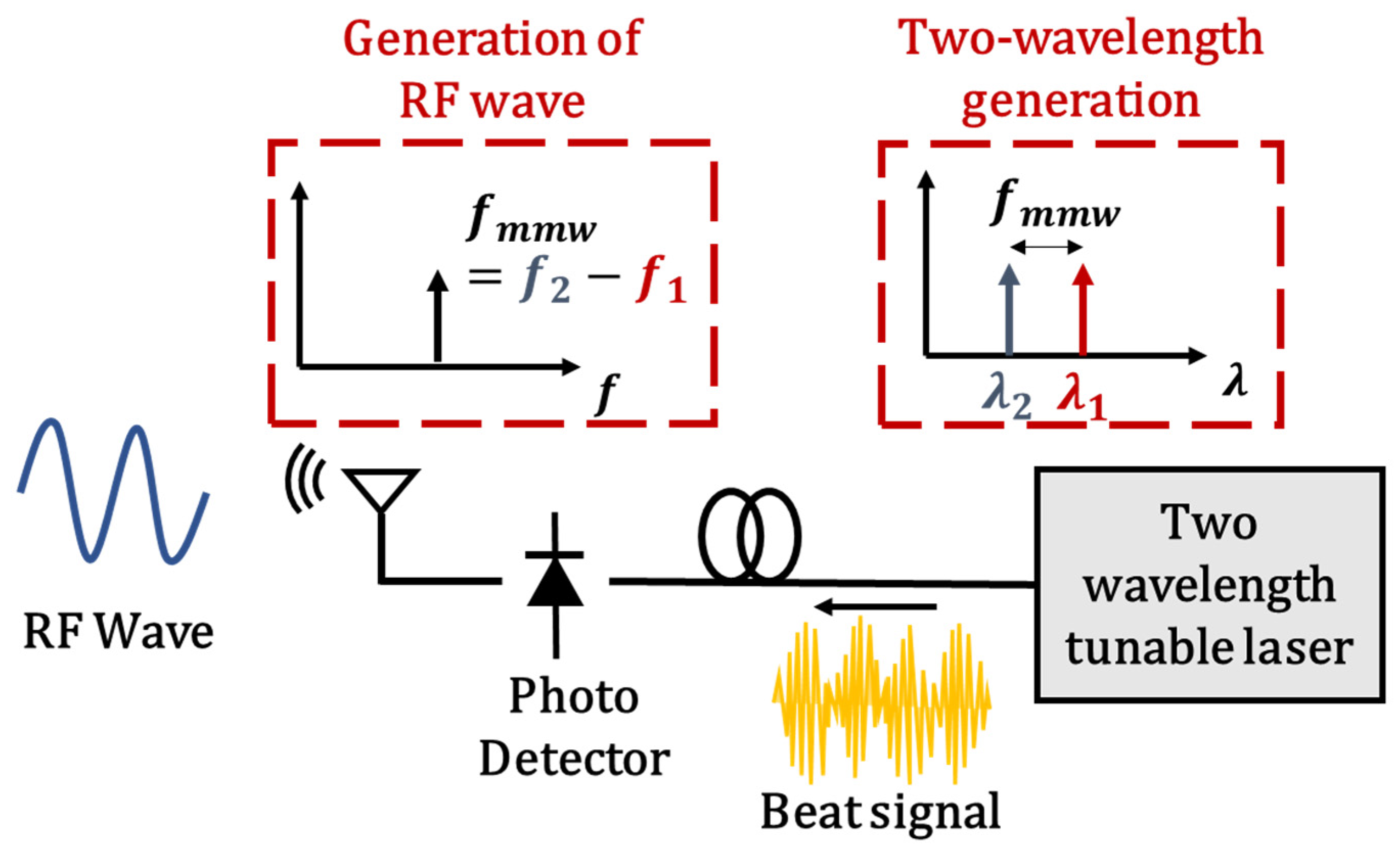
Ultra-high-frequency electromagnetic waves in the GHz to THz range, corresponding to the difference in frequency, are generated by incidenting two-wavelength light onto a high-speed photodetector (Figure 1). In this study, we report the structure and basic operation of a two-wavelength tunable laser (TWTL), as well as the generation of millimeter and sub-THz waves.
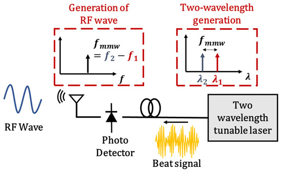
Figure 1.
Model of RF wave generation by two-wavelength tunable laser.
2. Principle and Structure
2.1. Structure of a TWTL
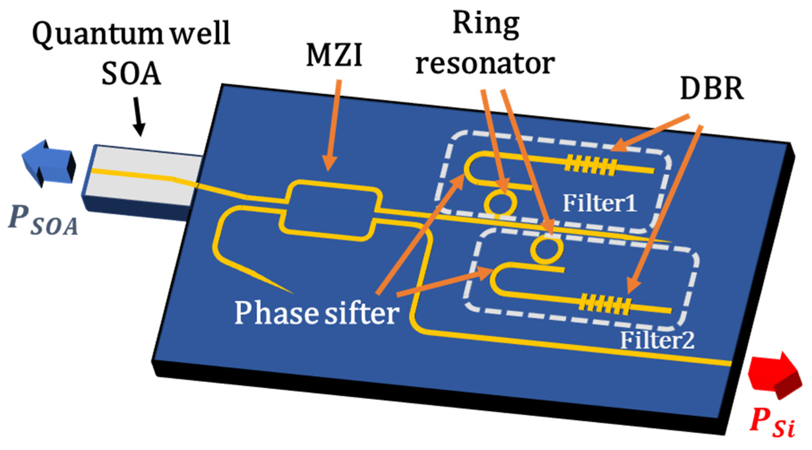
In this study, a TWTL, which integrates a two-wavelength tunable filter and a quantum well–semiconductor optical amplifier (QW–SOA) with 95% end-face reflectivity to achieve high output from the Si chip, was utilized. A schematic of this structure is shown in Figure 2.

Figure 2.
Structure of TWTL.
This laser forms a laser cavity between a distributed Bragg reflector (DBR) with a central reflection wavelength of approximately 1.54 µm and the end face of the SOA. Because the reflection bandwidth of the DBR and the resonance wavelength of the ring resonator are designed to be of similar magnitude, a single-wavelength oscillation is possible. By connecting these two sets of structures parallel to the SOA, the two wavelengths can be controlled independently. The unit closer to the SOA was designated as filter 1, whereas the unit further away was designated as filter 2. Additionally, a Mach–Zehnder interferometer (MZI) was installed between the two-wavelength filter and SOA. By controlling the path-length difference between the two arms using a micro heater, the intensity ratios of the reflectance (SOA-side output) and transmittance (chip-side output) can be adjusted. By taking output from the Si chip, the integration of optical modulators on the SOI platform becomes possible. PSi can be enhanced by increasing the transmittance of the MZI. However, if the transmittance is too high, the intensity of the feedback light from the two-wavelength filter decreases, making wavelength selection difficult. Therefore, the transmittance of the MZI was optimized to achieve the maximum PSi while maintaining wavelength selection for both wavelengths. To maximize PSi, a high-reflectivity SOA is used. Furthermore, each filter is equipped with a thermo-optic phase shifter, which allows independent control of the oscillation wavelengths and phases of the longitudinal modes.
2.2. Design Values for Each Structure
2.2.1. Ring Resonator
The schematic and dimensions of the ring resonator structure used in this study are shown in Figure 3.
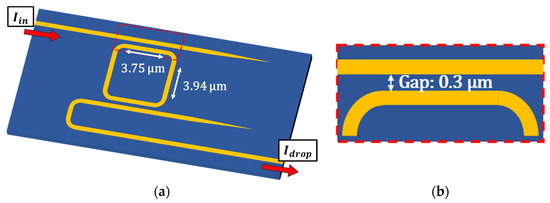
Figure 3.
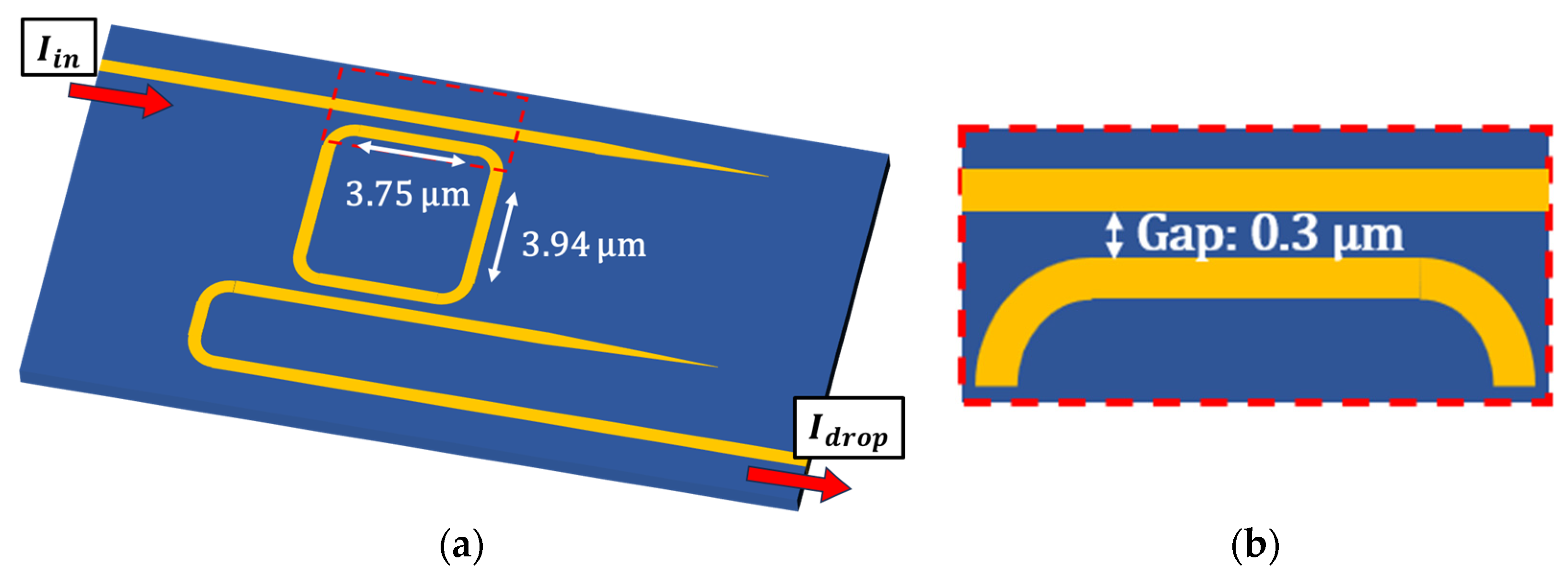
Structure of ring resonator. (a) Schematic of the entire ring resonator (b) Enlarged view of the coupling section.
As shown in Figure 3, the ring resonator used in this study was a racetrack type. The radius of the curved sections is 5 μm, resulting in a ring circumference of 46.8 μm and a free spectral range (FSR) of 11.7 nm. In addition, in the directional coupler that connects the bus waveguide to the ring resonator, the desired coupling efficiency is achieved by adjusting the length of the straight sections and the gap. For the current design, with a waveguide length of 3.75 μm, gap length of 0.3 μm, waveguide width of 0.40 μm, and waveguide height of 0.21 μm, the power coupling efficiency κ at a wavelength of 1545 nm is 0.101.
Figure 4 compares the theoretical [31] and measured values of the transmittance of the ring resonator, defined as the intensity ratio between the in port and drop ports. The internal loss of the ring resonator in the theoretical calculations was set to 1.5 dB/cm, and the peaks were normalized to 1.
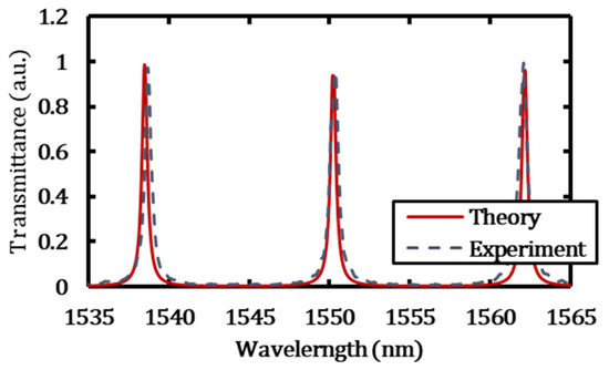
Figure 4.
Transmittance of ring resonator.
When comparing the Q factor at the peak at approximately 1538 nm, the theoretical value was 7742, whereas the measured value was 6347, confirming that the behavior is consistent with the design. In addition, by heating the waveguide using a micro heater mounted on the ring resonator, the effective refractive index changes owing to the thermo-optic effect, which increases the effective circumference of the ring and shifts the resonance wavelength towards longer wavelengths.
2.2.2. Distributed Bragg Reflector (DBR)
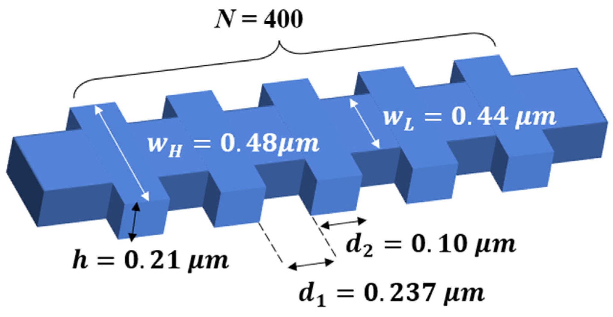
A DBR has a structure comprising alternating layers with different refractive indices, allowing for the selective reflection of light within a specific frequency band by adjusting the refractive indices and period. In this study, DBR achieved a layered structure by periodically varying the waveguide width to change the effective refractive index. A schematic diagram and the dimensions of the DBR used in this study are shown in Figure 5.

Figure 5.
Structure of DBR.
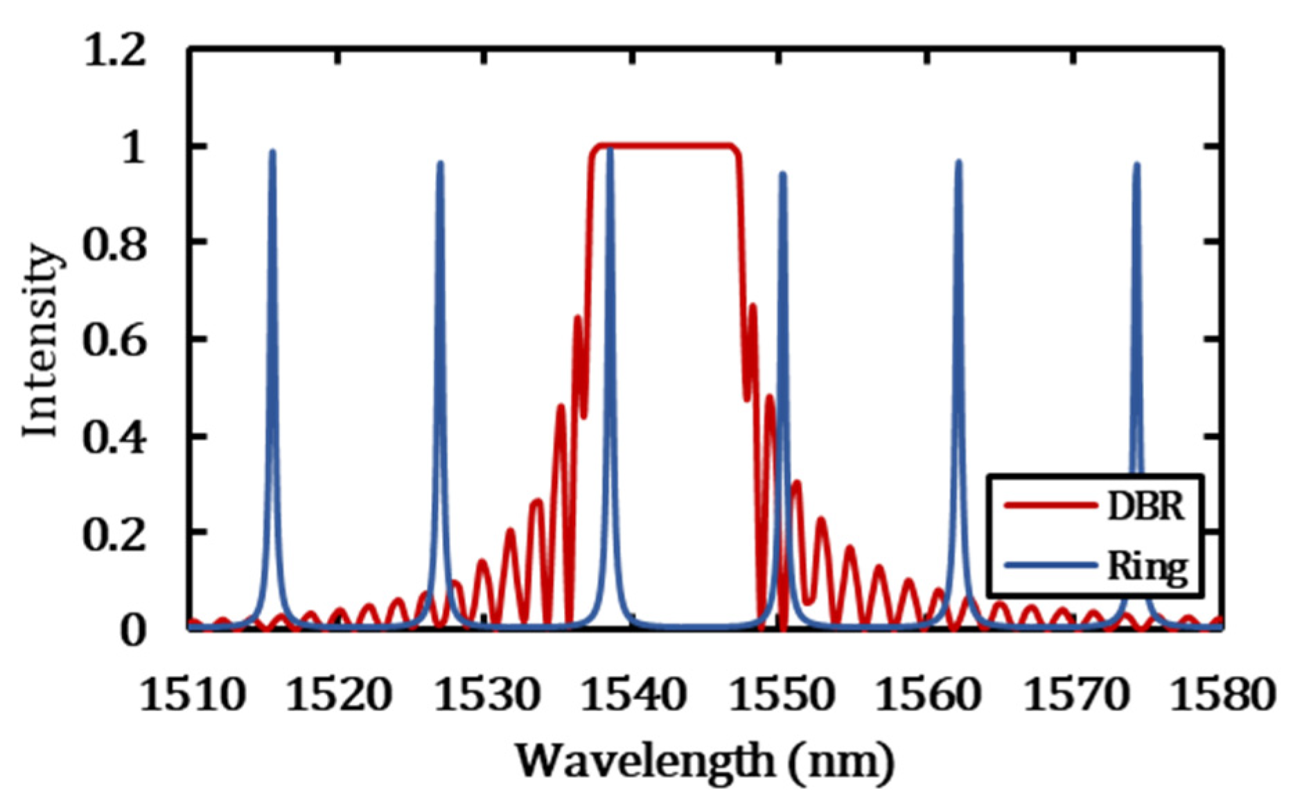
In this design, the DBR consisted of 400 periods so as to achieve a uniform and high reflectivity within a specific wavelength range. The reflected wavelength band corresponds to the C band, where the optical amplifier has a high gain. The waveguides width, lattice spacing, and duty cycle are designed to reflect only a single-ring resonator mode. Figure 6 shows a graph overlaying the calculated reflectivity of the DBR and the calculated transmittance of the ring resonator.
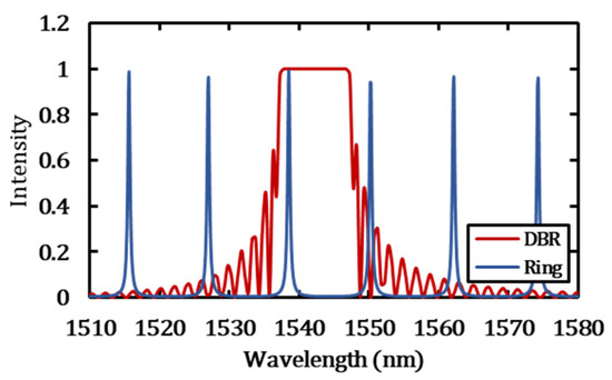
Figure 6.
Superposition of DBR reflectivity and ring resonator transmittance (theory).
The calculation results show that the central reflection wavelength of the DBR is 1542 nm and the reflection bandwidth (the range where the reflectivity is above 80%) is 10.4 nm. This value was slightly below the FSR of the ring resonator (11.7 nm), enabling single-wavelength oscillations and difference frequency generation over a broad frequency range.
2.2.3. Mach–Zehnder Interferometer (MZI)
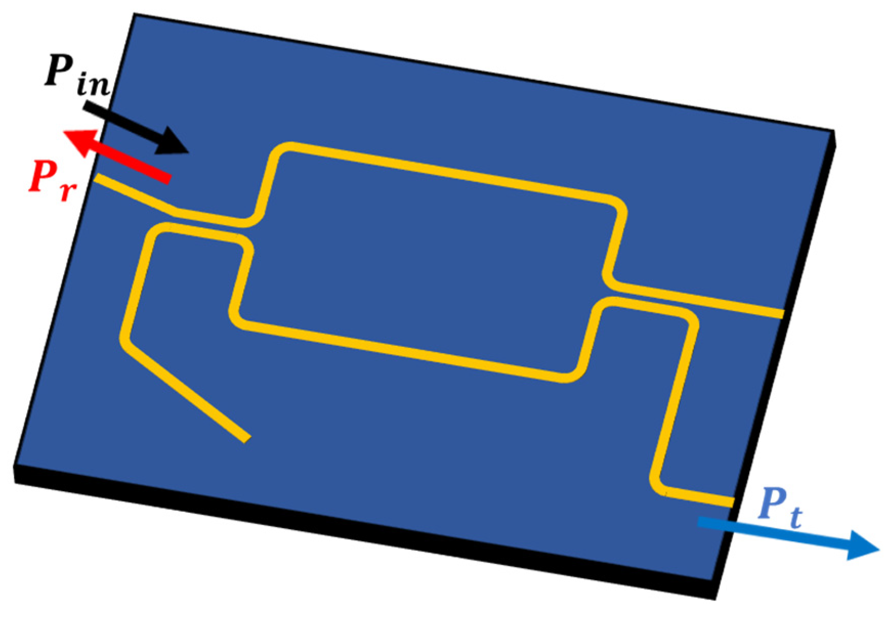
This device can adjust the intensity ratio between the SOA-side output and the Si-chip-side output by incorporating an MZI between the SOA and the two-wavelength filter. A schematic representation of the MZI is shown in Figure 7.
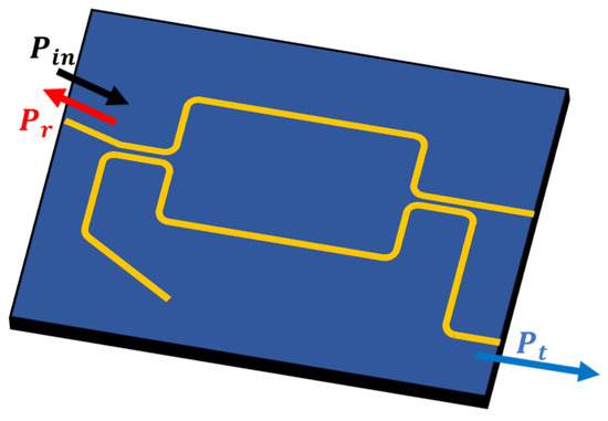
Figure 7.
Structure of MZI.
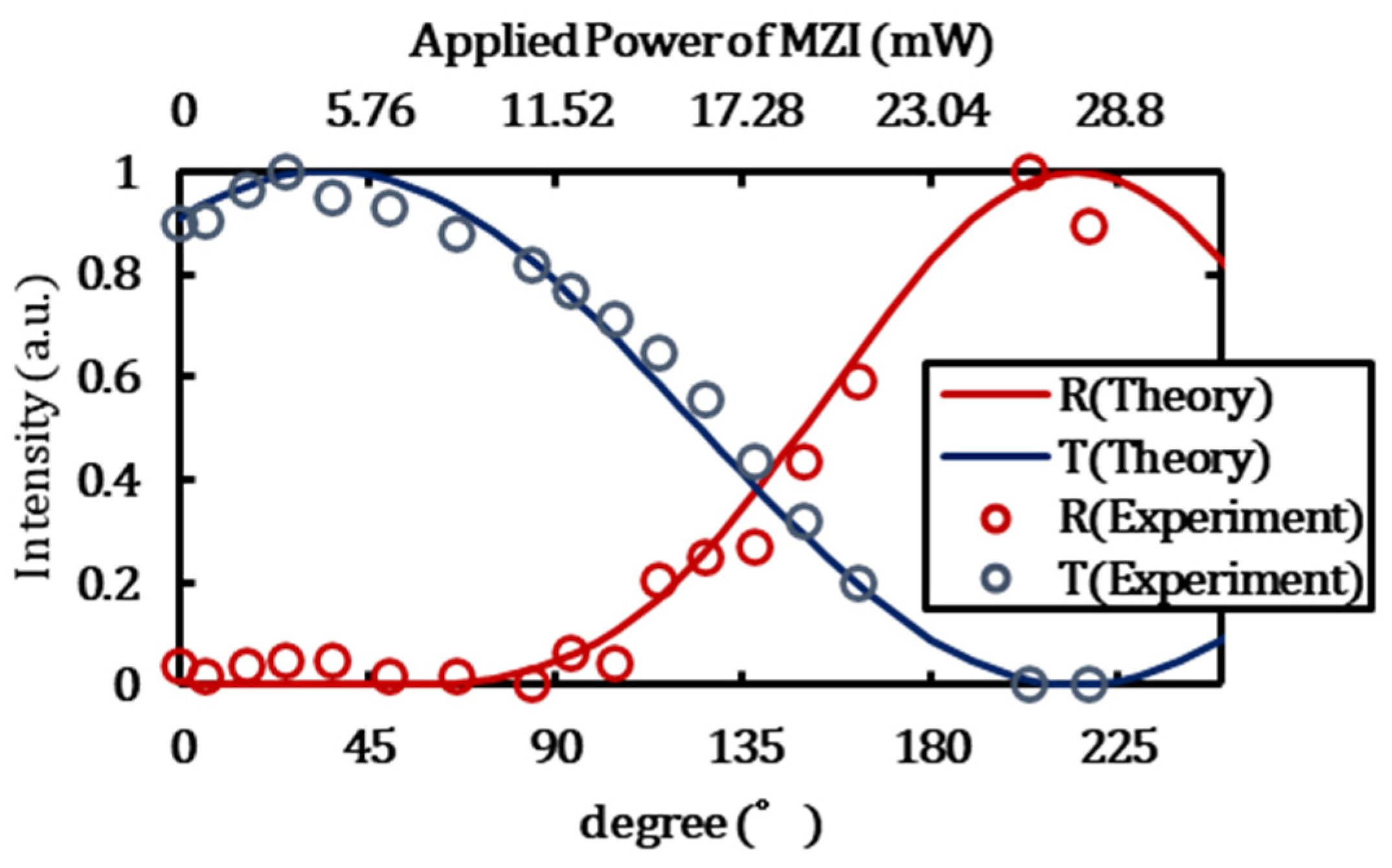
Let Pin be the light entering the SOA, Pr be the light returning towards the SOA, and Pt be the light exiting towards the Si-chip side. The ratio of light returning to the SOA can be defined as R (=Pr/Pin), and the ratio of light exiting the Si-chip side can be defined as T (=Pt/Pin). Based on these definitions, the following equation was obtained:
Here, represents the phase delay induced by heater heating, and represents the phase shift due to manufacturing errors. The normalized intensity ratios of the SOA output and the Si-chip-side output of the TWTL were fitted based on the reflection and transmission rates calculated from Equations (1) and (2). The fitting results are presented in Figure 8.
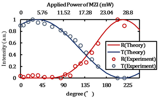
Figure 8.
Reflectance and transmittance of the MZI, with a phase shift due to manufacturing errors of 35°.
As shown in Figure 8, by heating one arm of the MZI and varying , the output ratio between the SOA side and Si-chip side can be controlled.
3. Experiment
Section 1, Section 2 and Section 3 describe the basic characteristics of the TWTL with an MZI, as explained in Section 2, and the generation of millimeter waves using the two-wavelength light obtained from the fiber-side output. Section 4 discusses the signal generation at approximately 300 GHz in the sub-THz band using a TWTL without an MZI.
3.1. Wavelength Tuning Characteristics
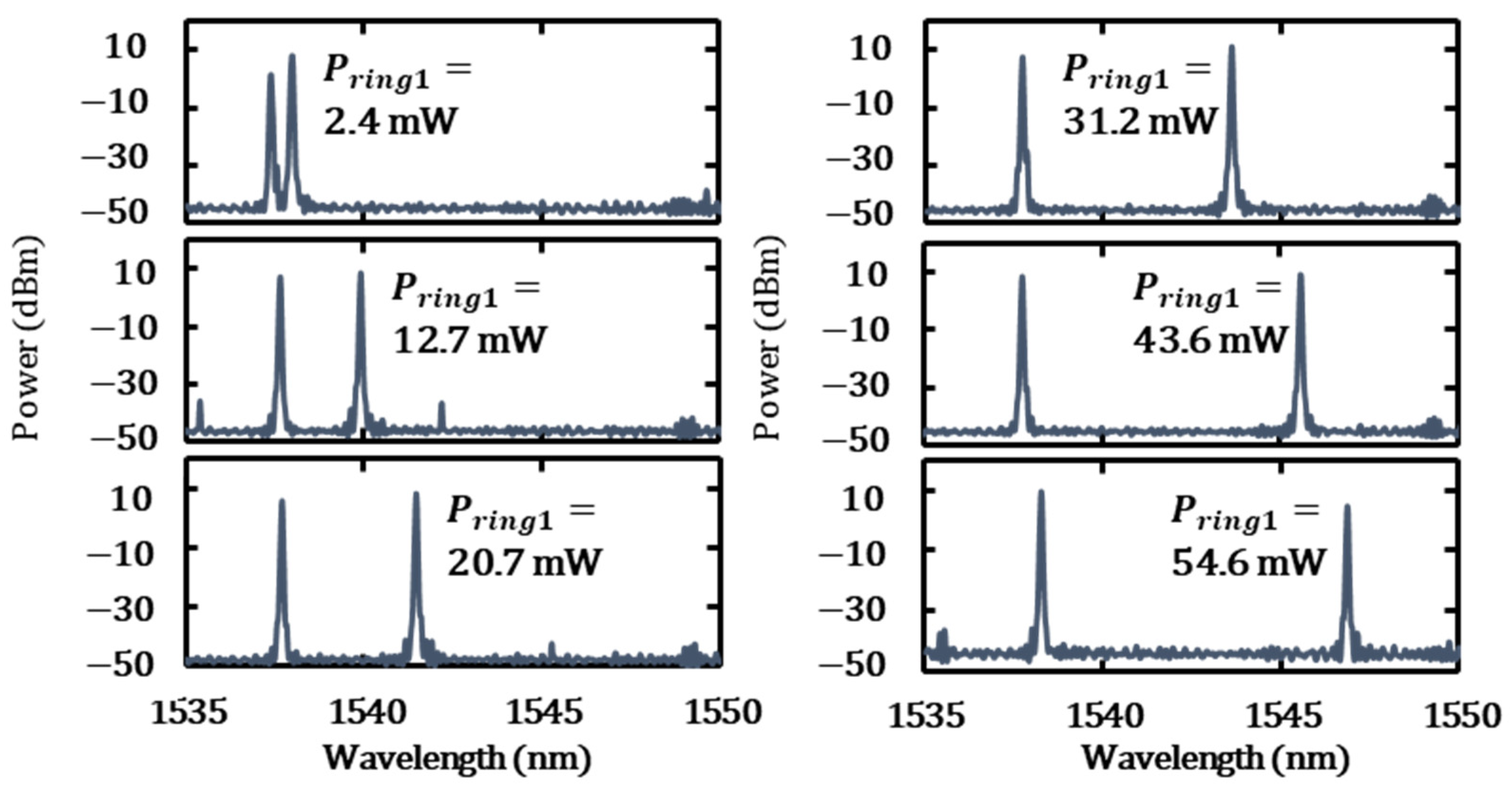
For the two-wavelength filter, when designating the ring resonator closer to the SOA as Ring 1 and the one that is farther away as Ring 2, the power applied to Ring 2 was fixed and the power applied to Ring 1 was varied. Two-wavelength interval tunability was measured by recording the fiber-side output using an optical spectrum analyzer. Figure 9 shows a graph of the two-wavelength tunability characteristics when the SOA injection current was set to 100 mA and the MZI applied power was 20.5 mW (with R = 62%).
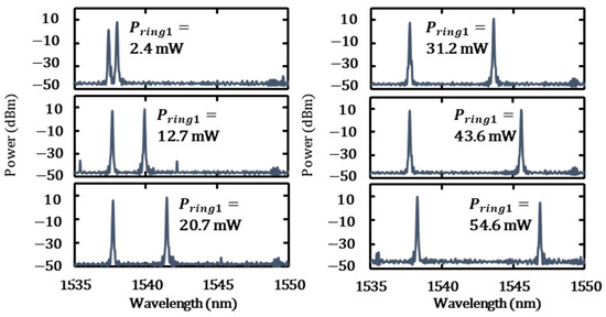
Figure 9.
Tunable two-wavelength characteristics of TWTL.
By applying power to Ring 1, the oscillation wavelength of Filter 1 shifted towards longer wavelengths. The oscillation wavelength of Filter 1 ranges from 1537.98 nm to 1546.86 nm, resulting in a wavelength tunability range of 8.88 nm. The maximum wavelength difference achieved is 8.60 nm, which corresponds to a difference frequency of 1077.5 GHz between the two wavelengths. Consequently, the efficiency of the difference in the frequency change per heater power was 19.2 GHz/mW.
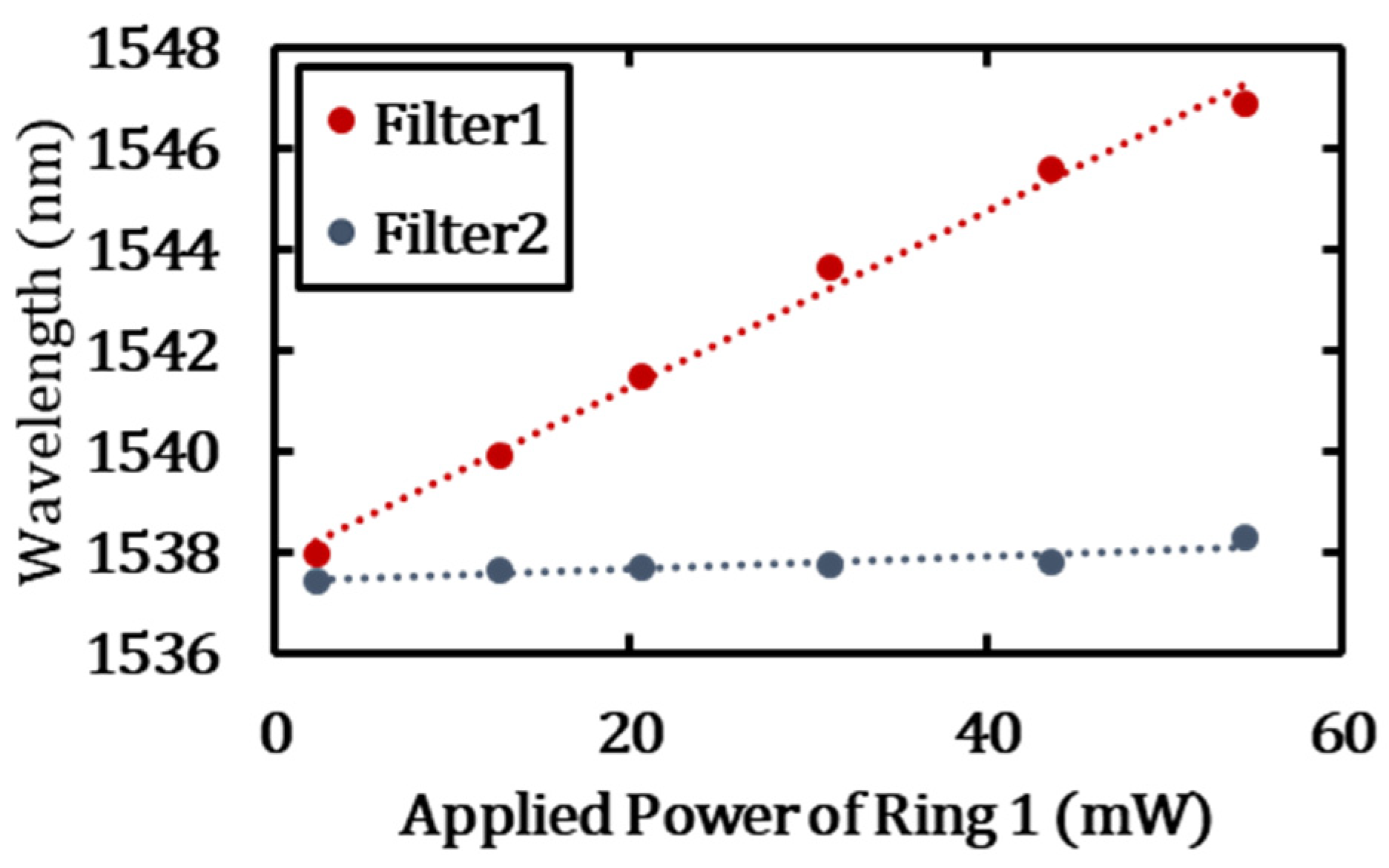
However, the oscillation wavelength of Filter 2 shifted slightly as power was applied to Ring 1. This shift was likely due to thermal crosstalk, in which the heat from the heater applied to Ring 1 was transferred to Ring 2. The relationship between the power applied to Ring 1 and the oscillation wavelength is shown in Figure 10.
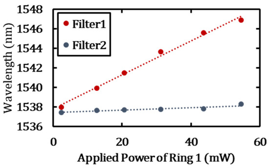
Figure 10.
Wavelength shift due to applied power of Ring 1.
As power ranging from 2.4 mW to 54.6 mW is applied to Ring 1, a wavelength shift of 8.8 nm is observed for Filter 1, while Filter 2 experiences a shift of 0.86 nm. This suggests that approximately 10% of the heat applied to Filter 1 affects Filter 2. In this experiment, the wavelength was controlled using only Ring 1 and Phase Shifter 1 in Filter 1. By the thermal crosstalk from Filter 1, the lasing wavelength was slightly changed with mode hopping. However, by appropriately controlling the phase of the longitudinal modes of the laser cavity and the resonant wavelength of the ring resonators with the four heaters, it is possible to finely control each wavelength regardless of the thermal crosstalk. Although the efficiency of frequency difference change decreased by 10% due to thermal crosstalk, the efficiency can be improved by increasing the distance between the ring resonators or by introducing thermal isolation grooves.
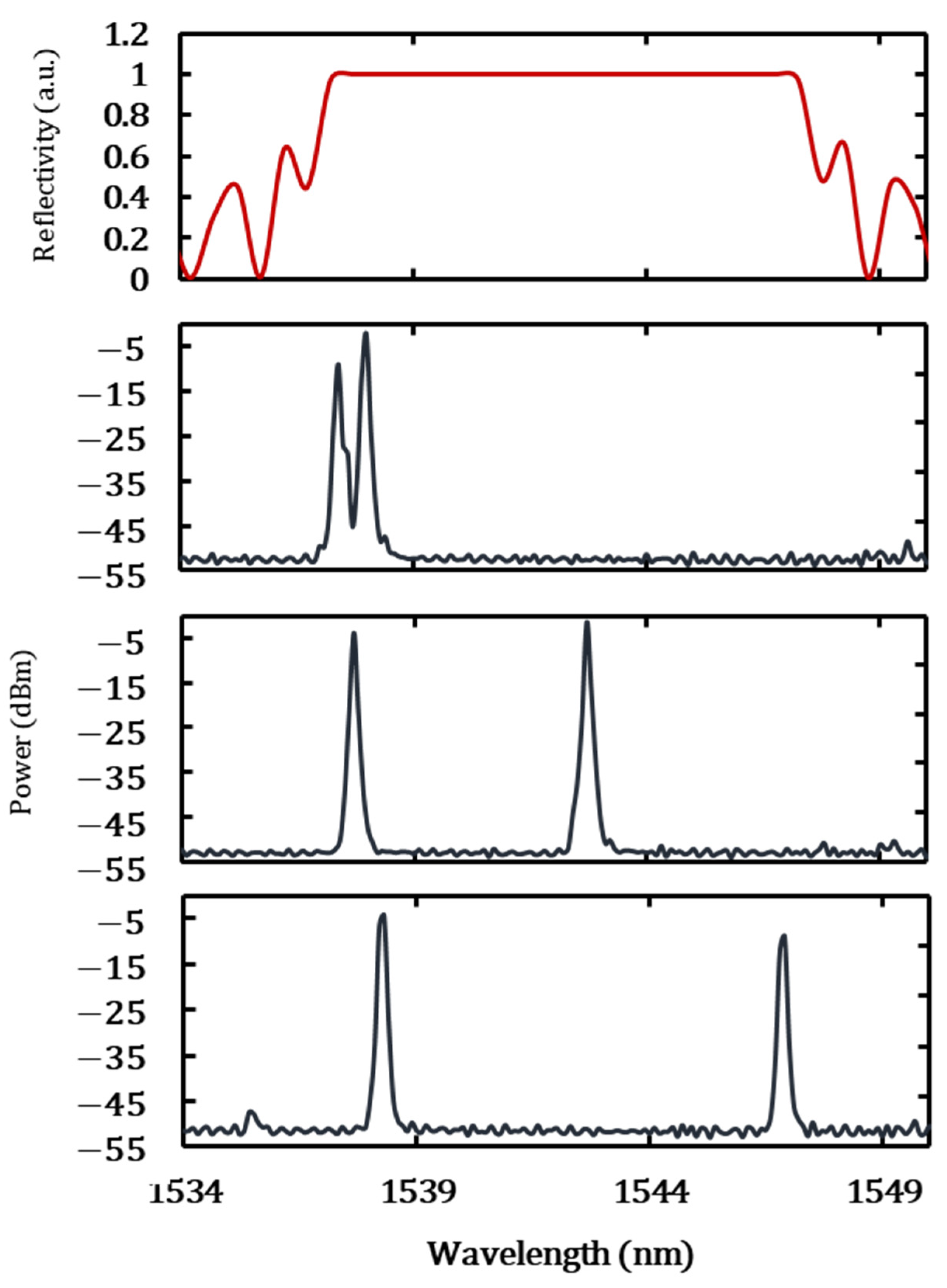
Figure 11 shows the overlap of the wavelength tunability characteristics of the TWTL with the calculated reflection bandwidth of the DBR.
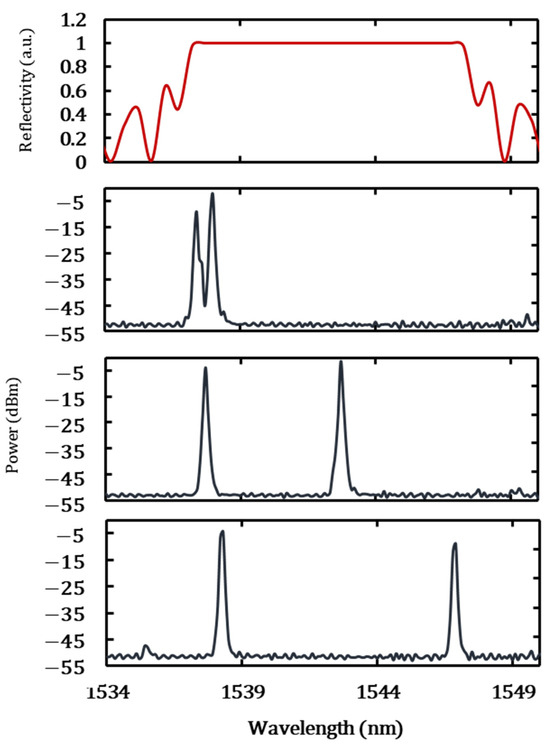
Figure 11.
Superposition of DBR reflectivity and wavelength tunable characteristics of TWTL.
As shown in Figure 11, the calculated reflection bandwidth of the DBR (1537.055 nm to 1547.450 nm) and the wavelength range of the TWTL (1537.44 nm to 1546.86 nm) are in good agreement, confirming that the designed wavelength tunability range has been achieved. In this way, the frequency difference is limited by the reflection bandwidth of the DBR, and the thermal crosstalk shown in Figure 10 does not pose a problem for the generation of the difference frequency. The minimum wavelength interval obtained from this measurement was 0.14 nm, which corresponds to a frequency difference of approximately 17 GHz. The reason for the minimum spacing of 0.14 nm between two wavelengths is that the feedback light to Ring 2 decreases due to the drop in Ring 1. At a full width at half maximum (FWHM) of 0.122 nm, corresponding to a frequency difference of 15 GHz, the feedback light intensity from Filter 2 to the SOA decreases by 6 dB. As a result, oscillation at two wavelengths becomes difficult.
3.2. L–I Characteristics
The dependence of the output light intensity on the reflectance, R, of the MZI was measured. Figure 12 shows the reflectance dependence of the light intensity received by a large-area photodiode (PD) for PSi and a lens module for the PSOA with SOA injection current fixed at 70 mA.
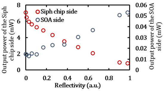
Figure 12.
Reflectivity dependence of each output (SOA injection current: 70 mA).
As shown in Figure 12, the maximum light intensity obtained was 7.09 mW at the chip-side output when the reflectance was low and 0.053 mW at the SOA-side output when the reflectance was high. The intensity variation was 6.17 dB on the chip side and 9.38 dB on the SOA side, demonstrating the ability to vary the intensity ratio over a broad range. The overall output from the SOA side, which is utilized as a monitor for the two-wavelength light, is low because the end-face reflectivity of the SOA is set to a high value of 95%. The key point is the ability to control the output intensity on the Si-chip side.
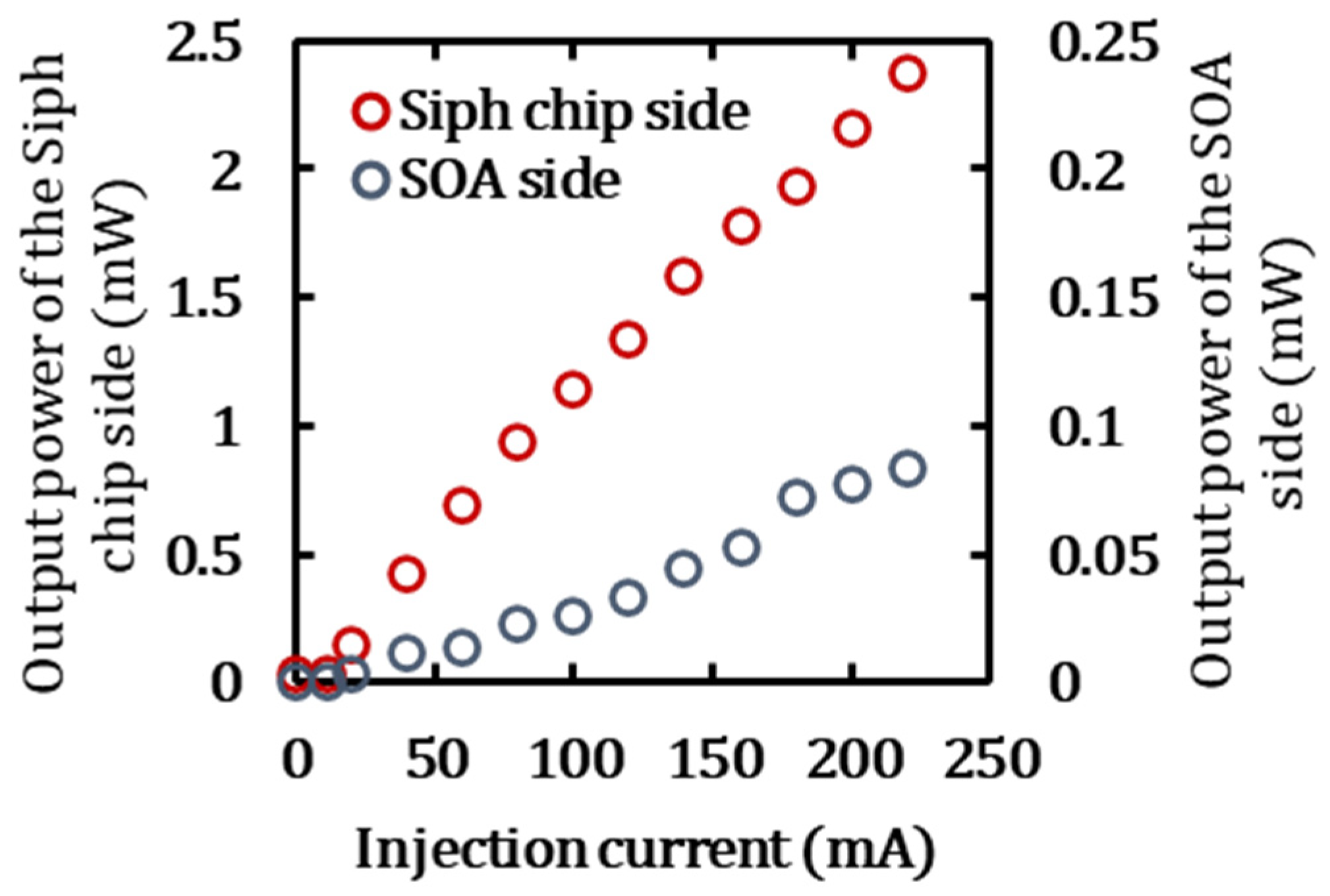
Next, as an example of laser output, the L–I characteristics for the SOA-side output and Si-chip-side output were measured with the MZI applied power set to 26.08 mW (reflectance 98%) for the two wavelengths with a difference frequency of 311 GHz (1540.22 nm and 1542.69 nm). The results are presented in Figure 13.

Figure 13.
L–I Curve at 98% reflectivity.
For a reflectance of 98%, the threshold current is 11.4 mA. Beyond 80 mA, the emission spectrum became unstable, and multimode oscillations were observed at currents exceeding 180 mA. The maximum stable light intensity at the Si-chip side was 0.93 mW at 80 mA. In a hybrid laser with a Si waveguide as the external resonator, an increase in optical intensity leads to a refractive index change caused by two-photon absorption in Si, resulting in laser oscillation instability. Under such unstable laser oscillation, longitudinal multi-mode oscillation is more likely to occur [29].
3.3. Millimeter Wave Generation
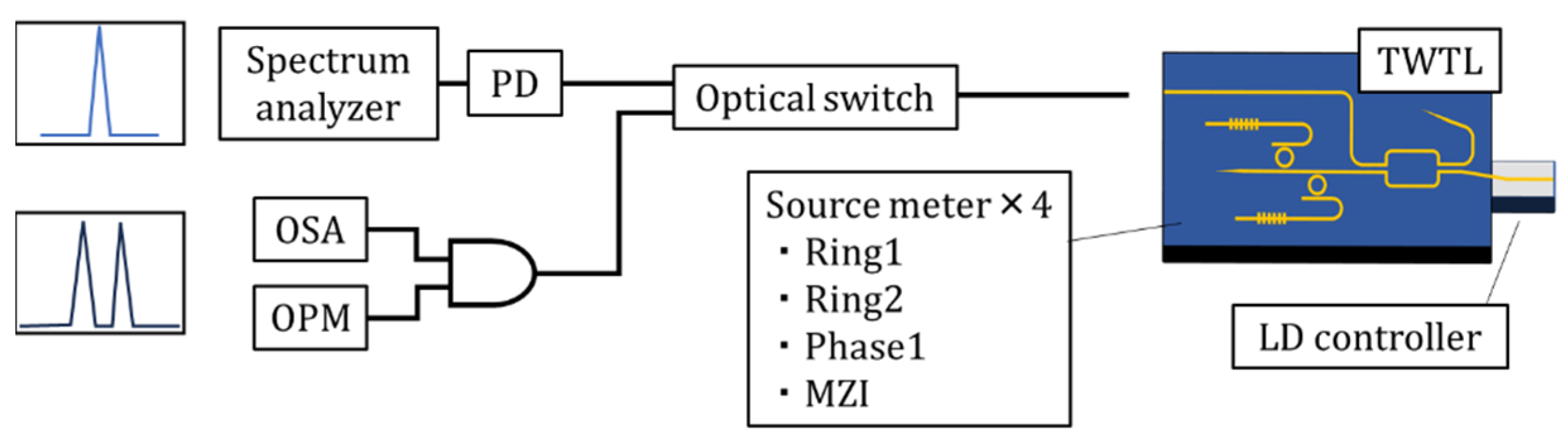
A schematic of the measurement setup for generating millimeter waves with a difference frequency of 17 GHz is shown in Figure 14.

Figure 14.
Millimeter wave measurement system.
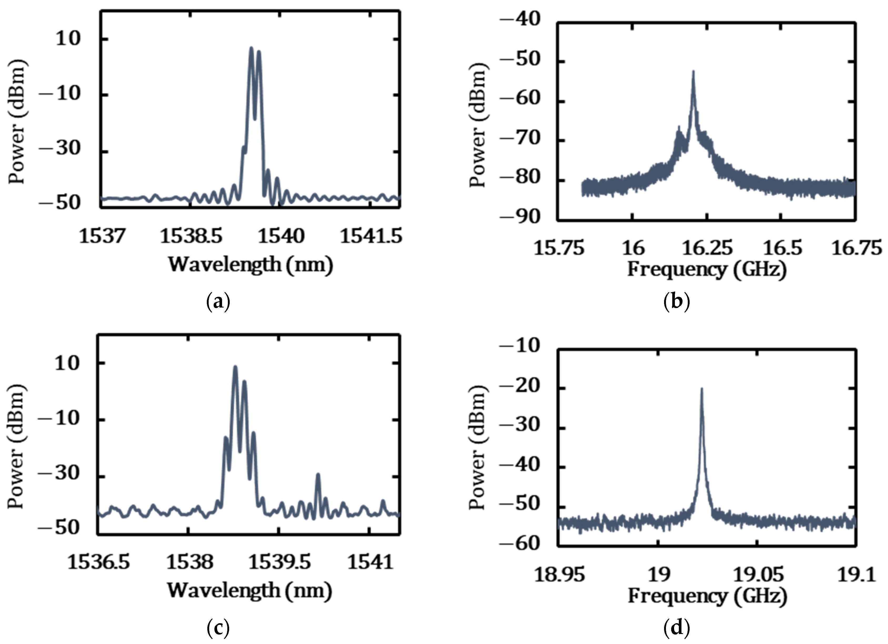
The high-speed photodiode used in this experiment (discovery semiconductors, DSC10ER) can detect frequencies up to 60 GHz, and the electrical signal analyzer (KEYSIGHT, N9010B) used for millimeter-wave detection can measure frequencies up to 44 GHz. Therefore, this measurement system can detect millimeter waves of up to 44 GHz. The Si-chip-side output was extracted by end-face coupling with a thin fiber. First, to examine the millimeter wave profiles when the reflectance is significantly varied, millimeter wave detection was performed at the reflectance of 94% and 7.2%. The optical and millimeter wave spectra at reflectance of 94% and 7.2% are shown in Figure 15a,b, and Figure 15c,d, respectively.
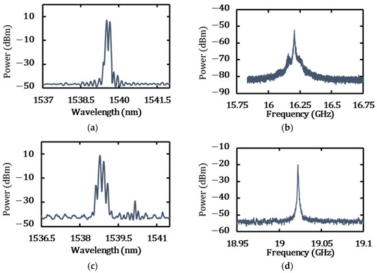
Figure 15.
Millimeter wave generation by the TWTL. (a) Two-wavelength optical spectrum; wavelength difference: 0.13 nm, frequency difference: 16.44 GHz. (b) Millimeter wave; frequency: 16.20 GHz, linewidth: 2.7 MHz. (c) Two-wavelength optical spectrum; wavelength difference: 0.14 nm, frequency difference: 17.72 GHz. (d) Millimeter wave; frequency: 19.02 GHz, linewidth: 420 kHz.
For millimeter-wave generation from two-wavelength light, phase matching between the two wavelengths is critical. If there is a phase mismatch between the two wavelengths, phase noise can be introduced into the electrical signal during optical–electrical (O–E) conversion, leading to instability in the electrical spectrum and potentially preventing the observation of millimeter waves. Therefore, in this measurement, a stable state was defined as the condition in which millimeter waves could be observed after the O–E conversion of two-wavelength light. The measurement results show that, at a reflectance of 94%, the maximum stable output was achieved with an SOA injection current of 40 mA, resulting in an optical intensity of 1.68 mW, millimeter wave linewidth of 2.7 MHz, millimeter wave intensity of −52.18 dBm, and conversion efficiency of −54.43 dB. In Figure 15b, a peak of approximately −70 dBm appears on the side about 50 MHz away from the main peak. This is likely attributed to electromagnetic noise from the external environment. At a reflectance of 7.2%, the maximum stable output was achieved with an SOA injection current of 100 mA, resulting in an optical intensity of 3.68 mW, a millimeter wave linewidth of 420 kHz, a millimeter wave intensity of −19.93 dBm, and a conversion efficiency of −25.59 dB. Focusing on Figure 15c, side peaks were observed alongside the two-wavelength peaks. These are due to four-wave mixing [8,32], which occurs when the phase between the two wavelengths is aligned. In this state, the millimeter wave linewidth becomes narrower. To improve conversion efficiency, the following measures can be taken: narrowing the millimeter wave linewidth, increasing the optical intensity, and reducing losses between devices. Assuming optimal phase conditions, increasing the incident optical intensity to 16 dBm would result in a PD conversion efficiency of −5.53 dB. Eliminating connection losses could enhance the millimeter wave output by up to 10.47 dB. The results suggest that, as the injection current to the SOA increases at lower reflectances, the output of the PSi becomes stable and high, and the millimeter-wave linewidth tends to become narrower. To validate this hypothesis, the SOA injection current was increased under stable output conditions for different reflectances, and the relationship between the reflectance, optical output intensity, and millimeter wave linewidth was measured. The measurement results are presented in Figure 16.
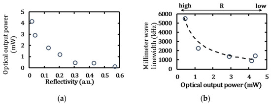
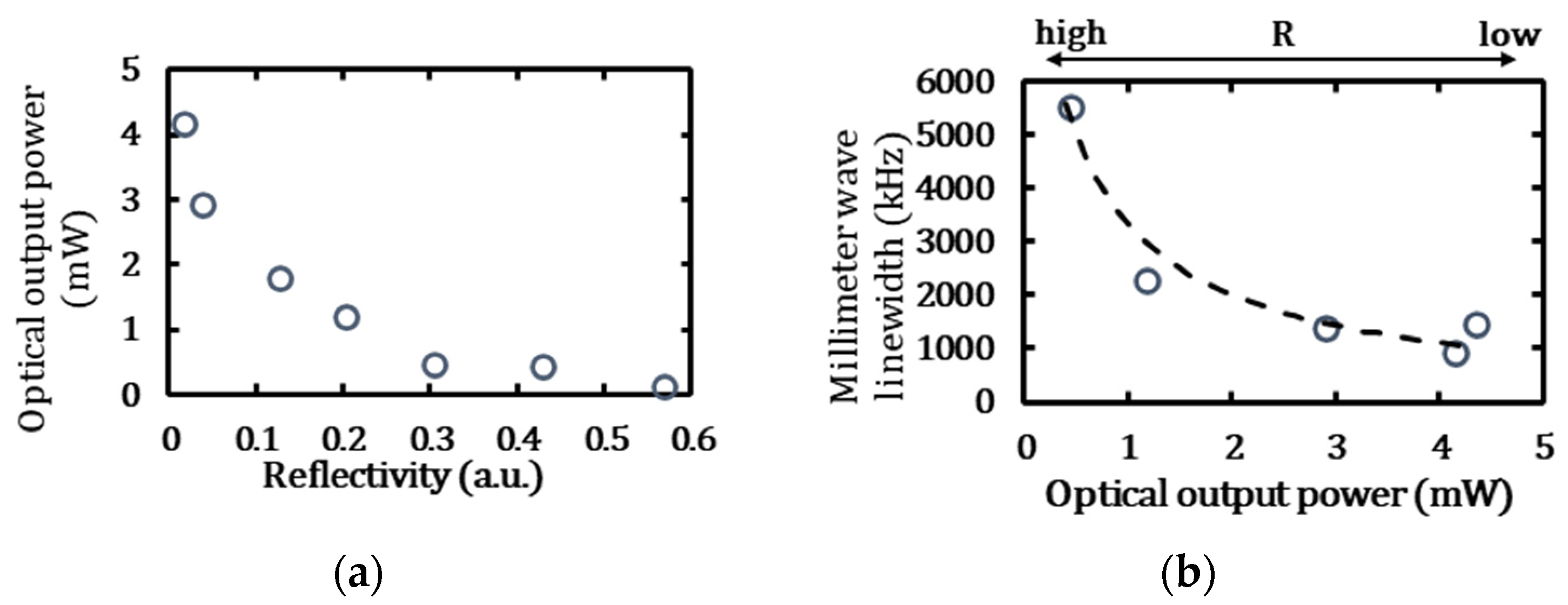
Figure 16.
(a) Relationship between reflectance and optical output intensity. (b) Relationship between optical output intensity and millimeter wave linewidth.
In this measurement, fine-diameter fibers were bonded to the Si chip to stabilize the alignment. The measurement results were corrected for this loss owing to a connection loss of 11.45 dB during bonding. As shown in Figure 16, a lower reflectance resulted in a more stable and higher optical output, and an inverse relationship between the optical intensity and millimeter-wave linewidth was observed. When the MZI reflectance is high, the optical intensity within the cavity increases. Because two-photon absorption occurs with a probability proportional to the square of the optical intensity, the overall output efficiency decreases [33]. Conversely, when the MZI reflectance was low, the overall output efficiency increased, allowing for a higher injection current into the SOA. Additionally, this leads to a higher output ratio on the Si-chip side, resulting in a stable, high output. However, if the reflectance is significantly reduced, the optical intensity within the cavity becomes insufficient, leading to unstable oscillations. As the laser output light intensity increases, the photon density within the laser cavity also increases, leading to a higher proportion of stimulated emission and a relative reduction in noise from spontaneous emission. Therefore, there is an inverse relationship between the output light intensity and the laser linewidth [28,29,30,34]. In particular, there is a positive correlation between the optical linewidth and millimeter-wave linewidth; thus, increasing the optical intensity and improving the q factor of the optical spectrum are effective methods to narrow the millimeter-wave linewidth.
3.4. THz Wave Generation
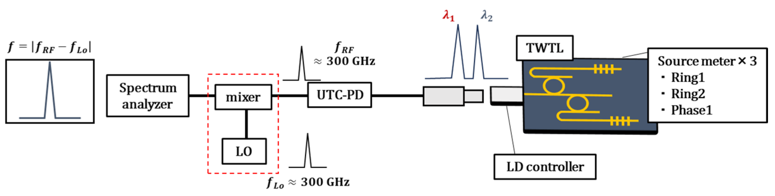
Using a device without MZI and simple control, we achieved high output intensity for the generation of sub-terahertz waves around a difference frequency of 300 GHz. Since the end-face reflectivity of the SOA is sufficiently low at 6%, it is possible to obtain an output comparable to or better than that of the device shown in Figure 14. A schematic of the measurement system is shown in Figure 17.
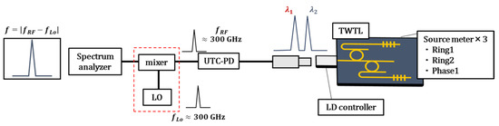
Figure 17.
Sub-THz wave measurement system.
In this experiment, two-wavelength light corresponding to a difference frequency of 300 GHz was output from the TWTL, and the sub-THz wave generated by the UTC-PD was mixed with , the 300 GHz output from the local oscillator (LO), to down-convert . A UTC-PD is the J-band Photomixer of NTT Innovative Devices. The sensitivity is 0.15 A/W, the output frequency range is 220–330 GHz, and the excitation light wavelength range is 1540–1560 nm. For down-converting the THz waves from the UTC-PD, the WR3.4SAX-M of VDI, which contains a mixer and local oscillator with 300 GHz, was used. A 300 GHz LO signal was generated by multiplying the 6.25 GHz frequency from the oscillator by 48 times, and the intrinsic mixer single-side band (SSB) conversion loss is 12 dB. This was measured using a spectral analyzer. For this purpose, the SOA side output of the TWTL was obtained, employing a QW–SOA with an end-face reflectivity of 6%.
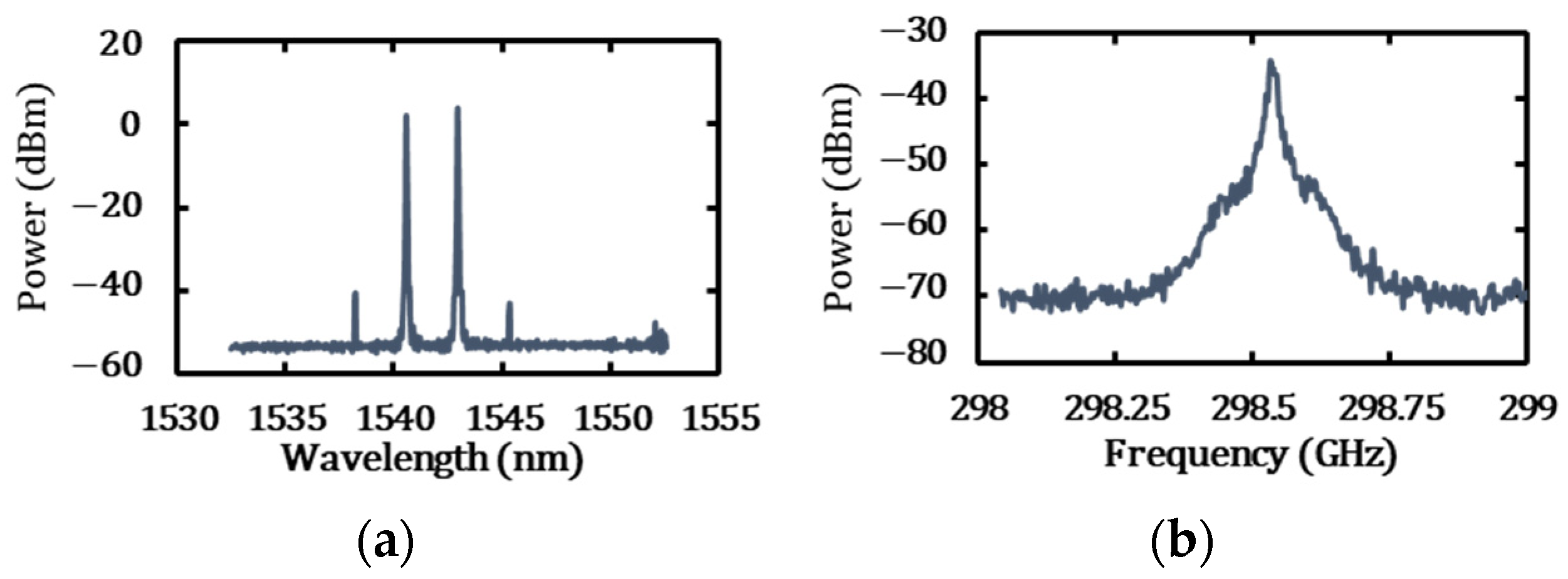
Figure 18 shows the spectra of the two-wavelength light with a difference frequency of 297.64 GHz and the sub-THz wave.

Figure 18.
Sub-THz wave generation. (a) Two-wavelength optical spectrum; SOA injection current: 132.66 mA, wavelength difference: 2.36 nm, frequency difference: 297.64 GHz, output power: 4.53 mW. (b) Sub-THz wave; frequency: 298.54 GHz, linewidth: 6.5 MHz.
Two-wavelength light exhibited side peaks owing to four-wave mixing. The optical intensity was 4.53 mW, linewidth of the detected sub-THz wave was 6.5 MHz. Given a 4.53 mW optical output and a UTC-PD conversion gain of −26 dB, the sub-terahertz wave output would be calculated as −19.44 dBm. Considering the 12 dB intrinsic mixer SSB conversion loss and a few dB of connection loss between the SOA and optical fiber, a THz wave detection intensity of −34.14 dBm is a reasonable value. For practical applications, since the output of the hybrid laser can be increased to around 16 dBm, the UTC-PD conversion gain would be −16.5 dB under these conditions. If connection losses can be reduced to 1 dB, the THz wave output could be increased to −1.5 dBm. In the experiment for sub-THz generation, the laser used did not have an MZI installed, making it difficult to control the photon density within the cavity. Additionally, the input power to the ring resonator and phase shifter was not optimized, which may have prevented the creation of optimal conditions for RF signal generation.
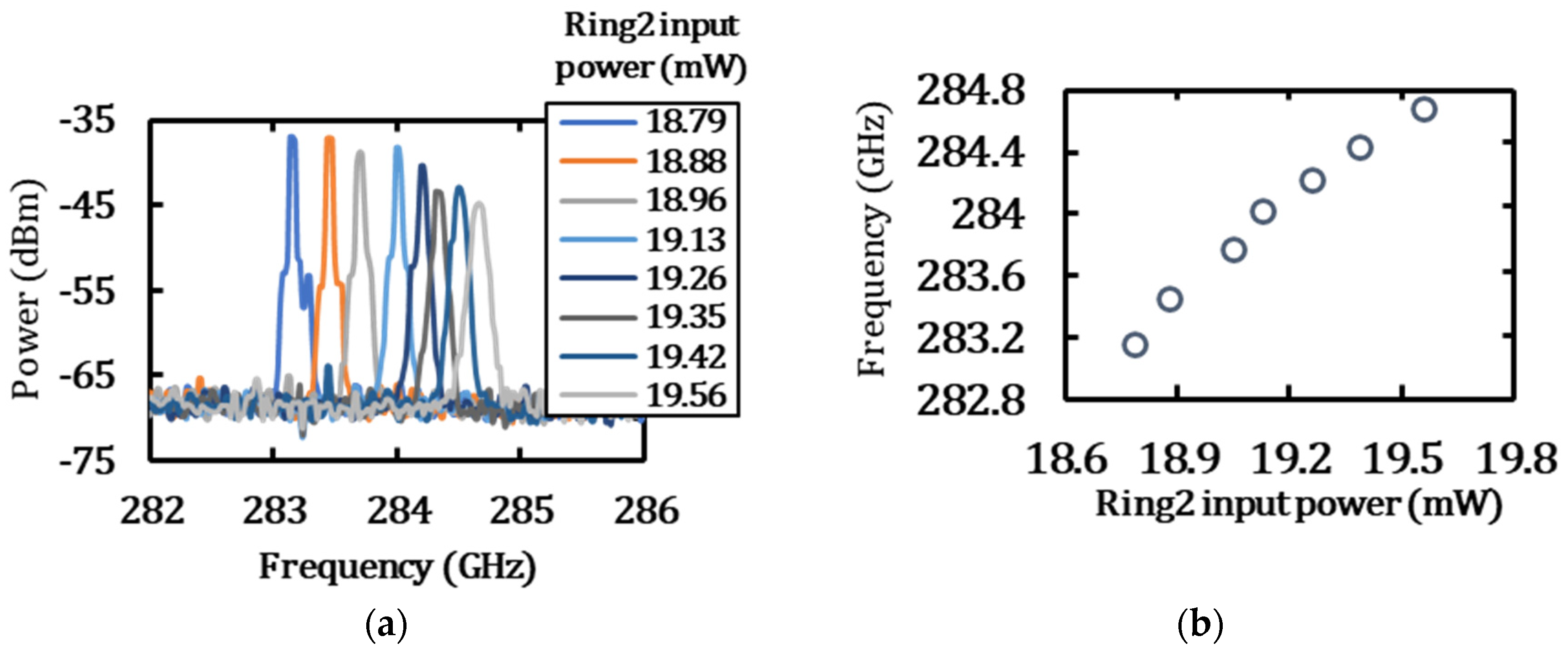
Finally, after generating two-wavelength light at a frequency difference of approximately 300 GHz, the tuning characteristics of the sub-THz wave were measured by gradually increasing the power applied to one side of the ring resonator. The measurement results are presented in Figure 19.
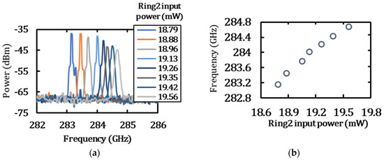
Figure 19.
Sub-THz Wave tuning. (a) Tuning characteristics. (b) Relationship between ring heater power and frequency shift.
As shown in Figure 19, the sub-THz waves generated by the TWTL can be continuously tuned over a frequency range of approximately 2 GHz, from 283 GHz to 285 GHz, with a tuning efficiency of 1.95 GHz/mW. In the tuning measurement, only one ring heater was adjusted. As a result, mode hopping occurred when the input power to Ring 2 was increased further, causing the sub-THz waves to disappear. To achieve continuous frequency tuning over a broader range, it is necessary to periodically adjust the longitudinal modes using a phase shifter. This adjustment would address the issue of decreasing sub-THz wave intensity with increasing frequency and enable broader tuning capabilities.
4. Discussion
In this section, we discuss the advantages of the TWTL developed in this study compared with two-wavelength light generation using silicon photonics from other groups, DFB lasers, and microcombs. In two-wavelength generation using silicon photonics [8], each unit is equipped with two ring resonators, which complicates wavelength control. By contrast, the device used in this method requires only one ring resonator per unit, allowing for simpler wavelength control and a more compact design. In addition, although the linewidth of the beat signal was estimated to be at least 424 kHz in other studies, our group demonstrated a linewidth below 100 kHz with lasers using silicon photonics [28,29]. In this study, we experimentally demonstrated an RF signal with a linewidth of 420 kHz. A minimum linewidth of 4 kHz was demonstrated in studies using external resonators. Therefore, we believe that similar techniques can be applied to the PSOA in our device to achieve narrower RF signal linewidths.
Compared with research using two DFB lasers [12], the linewidth of typical DFB lasers is more than 1 MHz, and the phase noise of the RF signal results from the phase noise of the two free-running DFB lasers. Consequently, the linewidth of the RF signal used in this study was 30 MHz. In contrast, our device is an external-cavity laser capable of generating linewidths below 100 kHz. Using the same cavity, phase noise could be reduced.
Finally, we compared our results with those of two-wavelength generation using microcombs [17,18,19,20,21,22,23,24]. Microcombs cover a broad range of coherent and evenly spaced frequencies with minimal phase errors. However, because two-wavelength light is extracted from multiple wavelength peaks using bandpass filters, the energy conversion efficiency can be low. In a paper [24] that extracted two-wavelength light for phase-locking with injection synchronization, the optical power after extracting an arbitrary wavelength from the comb was 2 μW, resulting in a total optical power of 4 μW for two wavelengths. Assuming a pump power of 150 mW for the comb [23], the energy conversion efficiency was 0.0027%. By contrast, the TWTL used in this study had an optical output power of 7.09 mW at an SOA injection current of 70 mA, translating into an energy conversion efficiency of approximately 8.9%. This is a significant advantage in terms of efficiency.
5. Conclusions
In this study, we discuss the high output on the Si-chip side, narrowing of the millimeter-wave linewidth, and detection and tuning characteristics of sub-THz waves using an MZI-equipped TWTL. Regarding the wavelength-tunable operation, the use of an MZI-equipped filter enabled the generation of difference frequencies up to 1077.5 GHz. In THz wave transceivers, the planned frequency usage is around the 300 GHz band, and therefore this difference in frequency characteristic sufficiently covers the required range. Additionally, by adjusting the MZI heater and reducing the SOA-side output ratio, a stable high output on the Si-chip side was achieved. A reciprocal relationship between the optical intensity and millimeter-wave linewidth was confirmed, with the smallest millimeter-wave linewidth achieved at 420 kHz.
In this study, by employing TWTL, we demonstrated an efficient two-wavelength output, narrow-linewidth millimeter-wave generation, signal generation in the 300 GHz band, and the capability to handle frequencies up to approximately 1 THz. With this structure, incorporating a silicon-photonics-based optical modulator [35] capable of intensity modulation and a compact UTC-PD [36,37,38,39] into a single chip enables the realization of a compact THz wave transceiver.
Author Contributions
Conceptualization, Y.T., A.S. and T.K.; methodology, Y.T., A.S. and T.K.; formal analysis, Y.T. and T.K.; investigation, Y.T. and T.K.; resources, T.K.; data curation, Y.T.; writing—original draft preparation, Y.T.; writing—review and editing, Y.T., A.S. and T.K.; visualization, Y.T.; supervision, T.K.; project administration, T.K.; funding acquisition, T.K. All authors have read and agreed to the published version of the manuscript.
Funding
This study was partly supported by Commissioned Research #JPJ012368C01301 of National Institute of Information and Communications Technology, Japan, A-STEP JPMJTR23RG of Japan Science and Technology Agency, SCOPE JP235003005 of Ministry of Internal Affairs and Communications, Japan, and JSPS KAKENHI Grant Number JP 23H01472 of Japan Society for the Promotion of Science.
Institutional Review Board Statement
Not applicable.
Informed Consent Statement
Not applicable.
Data Availability Statement
The raw data supporting the conclusions of this article will be made available by the authors on request.
Acknowledgments
We would like to express our sincere gratitude to Taiichi Otsuji of Tohoku University for allowing us to carry out the terahertz spectrum measurement experiments.
Conflicts of Interest
The funders had no role in the design of the study; in the collection, analyses, or interpretation of data; in the writing of the manuscript; or in the decision to publish the results.
References
- Rappaport, T.S.; Xing, Y.; Kanhere, O.; Ju, S.; Madanayake, A.; Mandal, S.; Alkhateeb, A.; Trichopoulos, G.C. Wireless communications and applications above 100 GHz: Opportunities and challenges for 6G and beyond. IEEE Access 2019, 7, 78729–78757. [Google Scholar] [CrossRef]
- Nagatsuma, T. Terahertz technologies: Present and future. IEICE Electron. Express 2011, 8, 1127–1142. [Google Scholar] [CrossRef]
- Nagatsuma, T.; Horiguchi, S.; Minamikata, Y.; Yoshimizu, Y.; Hisatake, S.; Kuwano, S.; Yoshimoto, N.; Terada, J.; Takahashi, H. Terahertz wireless communications based on photonics technologies. Opt. Express 2013, 21, 23736–23747. [Google Scholar] [CrossRef] [PubMed]
- Kim, J.-Y.; Nishi, H.; Song, H.J.; Fukuda, H.; Yaita, M.; Hirata, A.; Ajito, K. Compact and stable THz vector spectroscopy using silicon photonics technology. Opt. Express 2014, 22, 7178–7185. [Google Scholar] [CrossRef] [PubMed]
- Li, B.; Ye, S.; Che, M.; Tang, H.; Masutomi, N.; Mikami, Y.; Kato, K. Demonstration of THz frequency hopping in the 300 GHz band based on UTC-PD and tunable DFB laser array. Jpn. J. Appl. Phys. 2024, 63, 04SP86. [Google Scholar] [CrossRef]
- Kita, T.; Matsumoto, A.; Yamamoto, N.; Yamada, H. Tunable dual-wavelength heterogeneous quantum dot laser diode with a silicon external cavity. J. Light. Technol. 2018, 36, 219–224. [Google Scholar] [CrossRef]
- Masuda, W.; Iwanaga, K.; Matsumoto, A.; Kita, T. C-band tunable dual-wavelength laser with a quantum dot SOA. In Proceedings of the IEEE International Semiconductor Laser Conference, Potsdam, Germany, 10–14 October 2021. [Google Scholar] [CrossRef]
- Huang, X.; Doerr, C.R.; Qin, C.; Heanue, J.; Zhu, N.; Ton, D.; Guan, B.; Zhang, S.; Zhao, Y. Silicon-photonic laser emitting tunable dual wavelengths with highly correlated phase noise. Opt. Lett. 2021, 46, 142–145. [Google Scholar] [CrossRef] [PubMed]
- Kim, C.; Kim, I.; Li, G.; Lange, M.R.; Dimmick, T.E.; Langlois, P.; Reid, B. Optical Microwave/Millimeter-Wave Links Using Direct Modulation of Two-Section Gain-Coupled DFB Lasers. IEEE Photonics Technol. Lett. 2005, 17, 1734–1736. [Google Scholar] [CrossRef]
- Kim, N.; Shin, J.; Sim, E.; Lee, C.W.; Yee, D.-S.; Jeon, M.Y.; Jang, Y.; Park, K.H. Monolithic dual-mode distributed feedback semiconductor laser for tunable continuous-wave terahertz generation. Opt. Express 2009, 17, 13851–13859. [Google Scholar] [CrossRef]
- Fice, M.J.; Rouvalis, E.; van Dijk, F.; Accard, A.; Lelarge, F.; Renaud, C.C.; Carpintero, G.; Seeds, A.J. 146-GHz millimeter-wave radio-over-fiber photonic wireless transmission system. Opt. Express 2012, 20, 1769–1774. [Google Scholar] [CrossRef]
- Elwan, H.H.; Khayatzadeh, R.; Poette, J.; Cabon, B. Impact of Relative Intensity Noise on 60-GHz Radio-Over-Fiber Wireless Transmission Systems. J. Light. Technol. 2016, 34, 4751–4757. [Google Scholar] [CrossRef]
- Rahim, M.; Zeb, K.; Lu, Z.; Pakulski, G.; Liu, J.; Poole, P.; Song, C.; Barrios, P.; Jiang, W.; Zhang, X. Monolithic InAs/InP quantum dash dual-wavelength DFB laser with ultra-low noise common cavity modes for millimeter-wave applications. Opt. Express 2019, 27, 35368–35375. [Google Scholar] [CrossRef]
- Lu, Z.; Liu, J.; Mao, Y.; Zeb, K.; Liu, G.; Poole, P.J.; Weber, J.; Rahim, M.; Pakulski, G.; Song, C.; et al. Quantum dash multi-wavelength lasers for Tbit/s coherent communications and 5G wireless networks. J. Eur. Opt. Soc. Rapid Publ. 2021, 17, 9. [Google Scholar] [CrossRef]
- Zeb, K.; Lu, Z.; Liu, J.; Mao, Y.; Liu, G.; Poole, P.J.; Rahim, M.; Pakulski, G.; Barrios, P.; Vachon, M.; et al. Broadband Optical Heterodyne Millimeter-Wave-over-Fiber Wireless Links Based on a Quantum Dash Dual-Wavelength DFB Laser. J. Light. Technol. 2022, 40, 3698–3708. [Google Scholar] [CrossRef]
- Zhu, X.; La, X.; Guo, J.; Li, Z.; Zhao, L.; Wang, W.; Liang, S. A Novel High Speed Directly Modulated Dual Wavelength 1.3 µm DFB Laser for THz Communications. IEEE J. Sel. Top. Quantum Electron. 2023, 29, 1500306. [Google Scholar] [CrossRef]
- Nishimoto, K.; Minoshima, K.; Yasui, T.; Kuse, N. Generation of a microresonator soliton comb via current modulation of a DFB laser. OSA Contin. 2020, 3, 3218–3224. [Google Scholar] [CrossRef]
- Nishimoto, K.; Minoshima, K.; Yasui, T.; Kuse, N. Investigation of the phase noise of a microresonator soliton comb. Opt. Express 2020, 28, 19295–19303. [Google Scholar] [CrossRef]
- Bustos-Ramirez, R.; Trask, L.R.; Bhardwaj, A.; Hoefler, G.E.; Kish, F.A.; Delfyett, P.J. Optical synchronization between a 300 GHz frequency comb and a 10 GHz chip-scale MLL. In Proceedings of the IEEE Photonics Conference, IPC 2020, Rome, Italy, 10–14 November 2020; p. 9252549. [Google Scholar] [CrossRef]
- Kuse, N.; Navickaite, G.; Geiselmann, M.; Yasui, T.; Minoshima, K. Frequency-scanned microresonator soliton comb with tracking of the frequency of all comb modes. Opt. Lett. 2021, 46, 3400–3403. [Google Scholar] [CrossRef]
- Shirpurkar, C.; Bustos-Ramirez, R.; Trask, L.; Pericherla, S.; Briles, T.C.; Stone, J.R.; Yu, S.P.; Bhardwaj, A.; Hoefler, G.E.; Papp, S.B.; et al. Optical Synchronization between mmWave comb sources and a 10 GHz chip-scale mode-locked laser photonic integrated circuit. In Proceedings of the International Topical Meeting on Microwave Photonics, MWP 2021, Pisa, Italy, 15–17 November 2021. [Google Scholar] [CrossRef]
- Kuse, N.; Nishimoto, K.; Tokizane, Y.; Okada, S.; Navickaite, G.; Geiselmann, M.; Minoshima, K.; Yasui, T. Low phase noise THz generation from a fiber-referenced Kerr microresonator soliton comb. Commun. Phys. 2022, 5, 312. [Google Scholar] [CrossRef]
- Nishimoto, K.; Minoshima, K.; Yasui, T.; Kuse, N. Thermal control of a Kerr microresonator soliton comb via an optical sideband. Opt. Lett. 2022, 47, 281–284. [Google Scholar] [CrossRef]
- Matsumura, Y.; Tokizane, Y.; Hase, E.; Kuse, N.; Minamikawa, T.; Fujikata, J.I.; Kishikawa, H.; Haraguchi, M.; Okamura, Y.; Kaji, T.; et al. Carrier conversion from terahertz wave to dual-wavelength near-infrared light for photonic terahertz detection in wireless communication. Opt. Express 2023, 31, 33103–33112. [Google Scholar] [CrossRef] [PubMed]
- Chu, T.; Fujioka, N.; Ishizaka, M. Compact, lower-power-consumption wavelength tunable laser fabricated with silicon photonic-wire waveguide micro-ring resonators. Opt. Express 2009, 17, 14063–14068. [Google Scholar] [CrossRef]
- Fujioka, N.; Chu, T.; Ishizaka, M. Compact and low power consumption hybrid integrated wavelength tunable laser module using silicon waveguide resonators. J. Light. Technol. 2010, 28, 3115–3120. [Google Scholar] [CrossRef]
- Verdier, A.; de Valicourt, G.; Brenot, R.; Debregeas, H.; Dong, P.; Earnshaw, M.; Carrere, H.; Chen, Y.K. Ultrawideband wavelength-tunable hybrid external-cavity lasers. J. Light. Technol. 2018, 36, 37–43. [Google Scholar] [CrossRef]
- Nemoto, K.; Kita, T.; Yamada, H. Narrow-spectral-linewidth wavelength-tunable laser diode with Si wire waveguide ring resonators. Appl. Phys. Express 2012, 5, 082701. [Google Scholar] [CrossRef]
- Kita, T.; Tang, R.; Yamada, H. Narrow spectral linewidth silicon photonic wavelength tunable laser diode for digital coherent communication system. IEEE J. Select. Top. Quantum Electron. 2016, 22, 1500612. [Google Scholar] [CrossRef]
- Guan, H.; Novack, A.; Galfsky, T.; Ma, Y.; Fathololoumi, S.; Horth, A.; Huynh, T.N.; Roman, J.; Shi, R.; Caverley, M.; et al. Widely tunable, narrow-linewidth III-V/silicon hybrid external-cavity laser for coherent Communication. Opt. Express 2018, 26, 7920–7933. [Google Scholar] [CrossRef]
- Bogaerts, W.; De Heyn, P.; Van Vaerenbergh, T.; De Vos, K.; Kumar Selvaraja, S.K.; Claes, T.; Dumon, P.; Bienstman, P.; Van Thourhout, D.; Baets, R. Silicon microring resonators. Laser Photonics Rev. 2012, 6, 47–73. [Google Scholar] [CrossRef]
- Park, I.; Fischer, I.; Elsäßer, W. Highly nondegenerate four-wave mixing in a tunable dual-mode semiconductor laser. Appl. Phys. Lett. 2004, 84, 5189–5191. [Google Scholar] [CrossRef]
- Thoen, E.R.; Koontz, E.M.; Joschko, M.; Langlois, P.; Schibli, T.R.; Kärtner, F.X.; Ippen, E.P.; Kolodziejski, L.A. Two-photon absorption in semiconductor saturable absorber mirrors. Appl. Phys. Lett. 1999, 74, 3927–3929. [Google Scholar] [CrossRef]
- Henry, C.H. Theory of the linewidth of semiconductor lasers. IEEE J. Quantum Electron. 1982, 18, 259–264. [Google Scholar] [CrossRef]
- Wei, M.; Ma, H.; Sun, C.; Zhong, C.; Ye, Y.; Zhang, P.; Liu, R.; Li, J.; Li, L.; Tang, B.; et al. TDFA-Band Silicon Optical Variable Attenuator. Prog. Electromagn. Res. 2022, 174, 33–42. [Google Scholar] [CrossRef]
- Taiichi, O. 40-Gbit/s InP-based HEMT IC technology for future Lightwave communication systems. In Proceedings of the Annual Device Research Conference Digest, Charlottesville, VA, USA, 22–24 June 1998; pp. 4–5. [Google Scholar]
- Satou, A.; Otsuji, T. Recent Advances of Grating-Gate Transistors for Fast, Sensitive, Room-Temperature Plasmonic Terahertz Detection. In Proceedings of the IEEE Photonics Society Summer Topicals Meeting Series, SUM 2022, Cabo San Lucas, Mexico, 11–13 July 2022. [Google Scholar] [CrossRef]
- Satou, A.; Negoro, T.; Narita, K.; Hosotani, T.; Tamura, K.; Tang, C.; Lin, T.T.; Retaux, P.E.; Takida, Y.; Minamide, H.; et al. Gate-readout and a 3D rectification effect for giant responsivity enhancement of asymmetric dual-grating-gate plasmonic terahertz detectors. Nanophotonics 2023, 12, 4283–4295. [Google Scholar] [CrossRef]
- Tsung-Tse, L.; Mitsuki, W.; Dai, N.; Keisuke, K.; Masato, Y.; Tetsuya, S.; Taiichi, O.; Akira, S. Efficient optical-to-sub-THz carrier frequency down-conversion by UTC-PD-integrated HEMT. In Proceedings of the International Topical Meeting on Microwave Photonics, MWP 2023, Nanjing, China, 15–18 October 2023. [Google Scholar] [CrossRef]


Disclaimer/Publisher’s Note: The statements, opinions and data contained in all publications are solely those of the individual author(s) and contributor(s) and not of MDPI and/or the editor(s). MDPI and/or the editor(s) disclaim responsibility for any injury to people or property resulting from any ideas, methods, instructions or products referred to in the content. |
© 2024 by the authors. Licensee MDPI, Basel, Switzerland. This article is an open access article distributed under the terms and conditions of the Creative Commons Attribution (CC BY) license (https://creativecommons.org/licenses/by/4.0/).