The Correction Method for Wavefront Aberration Caused by Spectrum-Splitting Filters in Multi-Modal Optical Imaging System

Abstract
1. Introduction
2. Theory and Analysis Model
3. Design and Control Method
3.1. The Performance of Ideal Imaging System without Dichroic Coating
3.2. The Mechanism of Wavefront Error Introduced by Dichroic Film
3.3. The Correction Method for Wavefront Aberration Caused by Spectrum-Splitting Filters
4. Simulation and Experimental Verification
4.1. Optimization and Performance
4.2. Experimental Verification
5. Conclusions
Author Contributions
Funding
Institutional Review Board Statement
Informed Consent Statement
Data Availability Statement
Acknowledgments
Conflicts of Interest
References
- Wang, Y.; Li, L.; Gu, Z.; Wang, Y.; Lian, M. Image Quality Checkout Technique for Optical Camera of GF-4 Satellite. Spacecr. Recovery Remote Sens. 2016, 37, 80–86. [Google Scholar]
- Tong, C.; Bao, Y.; Huang, Q. Progress on Solar-induced Chlorophyll Fluorescence of Satellite Remote Sensing. Spacecr. Recovery Remote Sens. 2022, 43, 45–55. [Google Scholar]
- Cao, H.Y.; Zhang, X.W.; Zhao, C.G. System design and key technolongies of the GF-7 satellite. Chin. Space Sci. Technol. 2020, 40, 1–7. [Google Scholar]
- Liu, X.; Li, Y.; Liu, K. Polarization Aberration Control for Hyper-NA Lithographic Projection Optics at Design Stage. In Proceedings of the 2015 International Conference on Optical Instruments and Technology: Optical Systems and Modern Optoelectronic Instruments, Beijing, China, 17–19 May 2015; Volume 9618. [Google Scholar]
- Doering, D.; Forcht, K. Coating-induced wave front aberrations. In Proceedings of the Optical Design and Engineering III, Glasgow, UK, 2–5 September 2008; Volume 7100. [Google Scholar]
- Duddles, N.J. Effects of Mo-Si multilayer coatings on the imaging characteristics of an extreme-ultraviolet lithography system. Appl. Opt. 1998, 37, 3533. [Google Scholar] [CrossRef] [PubMed]
- Chipman, R.A. Polarization analysis of optical systems. Opt. Eng. 1989, 28, 90–99. [Google Scholar] [CrossRef]
- Di, H.; Hua, H.; Cui, Y.; Hua, D.; Li, B.; Song, Y. Correction technology of a polarization lidar with a complex optical system. J. Opt. Soc. Am. A 2016, 33, 1488–1494. [Google Scholar] [CrossRef] [PubMed]
- Souaidiaa, N.; Moyerb, D.; Meisterc, G.; Pellicorid, S.; Waluschkae, E.; Vossa, K. MODIS polarization ray tracing analysis. In Proceedings of the Polarization Science and Remote Sensing II, San Diego, CA, USA, 31 July–4 August 2005; Volume 5888. [Google Scholar]
- Eric, C.F. VIIRS polarization sensitivity testing and analysis. In Proceedings of the Polarization Science and Remote Sensing IV, San Diego, CA, USA, 2–6 August 2009; Volume 7461. [Google Scholar]
- Cui, C.; An, N.; Yu, Z.; Zhang, S.; Wang, W.; Xu, P. Suppression and Measurement of Polarization Response of the Solarinduced Chlorophyll Fluorescence Imaging Spectrometer. Spacecr. Recovery Remote Sens. 2022, 43, 85–96. [Google Scholar]
- Reily, D.J.; Chipman, R.A. Coating-Induced Wavefront Aberrations, Polarization Analysis and Measurement. In Proceedings of the Polarization Analysis and Measurement, San Diego, CA, USA, 22–22 July 1992; Volume 1746, pp. 139–146. [Google Scholar]
- Rabinovitch, K. Polarization effects in optical thin films. In Proceedings of the Optical Interference Coatings, Grenoble, France, 5–10 June 1994; Volume 2253, pp. 89–102. [Google Scholar]
- Samad, E.; Lan, S.; Synborski, C. Coating induced phase aberration in a Schwarzschild objective. In Proceedings of the Thin-Film Coatings for Optical Applications V, San Diego, CA, USA, 10–14 August 2008; Volume 7067. [Google Scholar]
- Kye, J.; McIntyre, G.; Yamamoto, N.; Levinson, H.J. Polarization aberration analysis in optical lithography systems. In Proceedings of the Optical Microlithography XIX, San Diego, CA, USA, 9–24 February 2006; Volume 6154. [Google Scholar]
- Geh, B.; Ruoff, J. The impact of projection lens polarization properties on lithographic process at hyper-NA. In Proceedings of the Optical Microlithography XX, San Diego, CA, USA, 25 February–2 March 2007; Volume 6520. [Google Scholar]


| Parameter | Specification |
|---|---|
| Wavelength [nm] | 450~900 |
| Field of views [°] | 1.4 |
| Focal length [mm] | 100 |
| F/# | 6.5 |
| Composite Wavefront error [λ] | 0.031 |
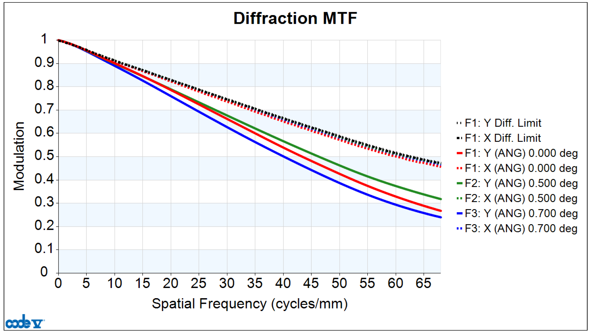
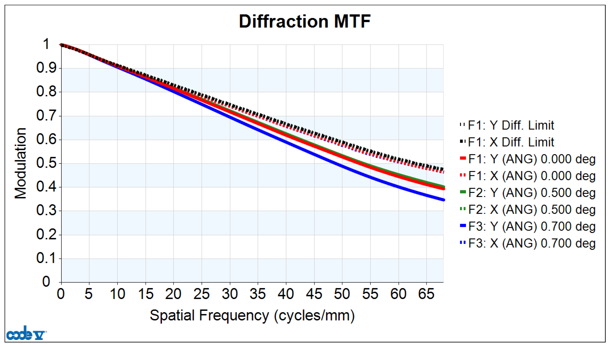
| Mean value of MTF@68 lp/mm | 0.465 |
| Distortion [%] | 0.6 |
| Meridional MTF | Sagittal MTF | |
|---|---|---|
| Dichroic I system | 0.09 | 0.177 |
| Dichroic II system | 0.153 | 0.177 |
Disclaimer/Publisher’s Note: The statements, opinions and data contained in all publications are solely those of the individual author(s) and contributor(s) and not of MDPI and/or the editor(s). MDPI and/or the editor(s) disclaim responsibility for any injury to people or property resulting from any ideas, methods, instructions or products referred to in the content. |
© 2024 by the authors. Licensee MDPI, Basel, Switzerland. This article is an open access article distributed under the terms and conditions of the Creative Commons Attribution (CC BY) license (https://creativecommons.org/licenses/by/4.0/).
Share and Cite
Liu, X.; Huang, Y.; Yan, X.; Wang, L.; Li, Q.; Zhang, T.; Hu, B.; Lei, W.; Mu, S.; Zhang, X. The Correction Method for Wavefront Aberration Caused by Spectrum-Splitting Filters in Multi-Modal Optical Imaging System. Photonics 2024, 11, 876. https://doi.org/10.3390/photonics11090876
Liu X, Huang Y, Yan X, Wang L, Li Q, Zhang T, Hu B, Lei W, Mu S, Zhang X. The Correction Method for Wavefront Aberration Caused by Spectrum-Splitting Filters in Multi-Modal Optical Imaging System. Photonics. 2024; 11(9):876. https://doi.org/10.3390/photonics11090876
Chicago/Turabian StyleLiu, Xiaolin, Ying Huang, Xu Yan, Li Wang, Qiang Li, Tingcheng Zhang, Bin Hu, Wenping Lei, Shengbo Mu, and Xiaohong Zhang. 2024. "The Correction Method for Wavefront Aberration Caused by Spectrum-Splitting Filters in Multi-Modal Optical Imaging System" Photonics 11, no. 9: 876. https://doi.org/10.3390/photonics11090876
APA StyleLiu, X., Huang, Y., Yan, X., Wang, L., Li, Q., Zhang, T., Hu, B., Lei, W., Mu, S., & Zhang, X. (2024). The Correction Method for Wavefront Aberration Caused by Spectrum-Splitting Filters in Multi-Modal Optical Imaging System. Photonics, 11(9), 876. https://doi.org/10.3390/photonics11090876