Link Bandwidth and Transmission Capability of Single-Mode Multi-Aperture Vertical-Cavity Surface-Emitting Lasers at 100 G/Lane and 200 G/Lane over Multimode Fibers

 , , and
Abstract
1. Introduction
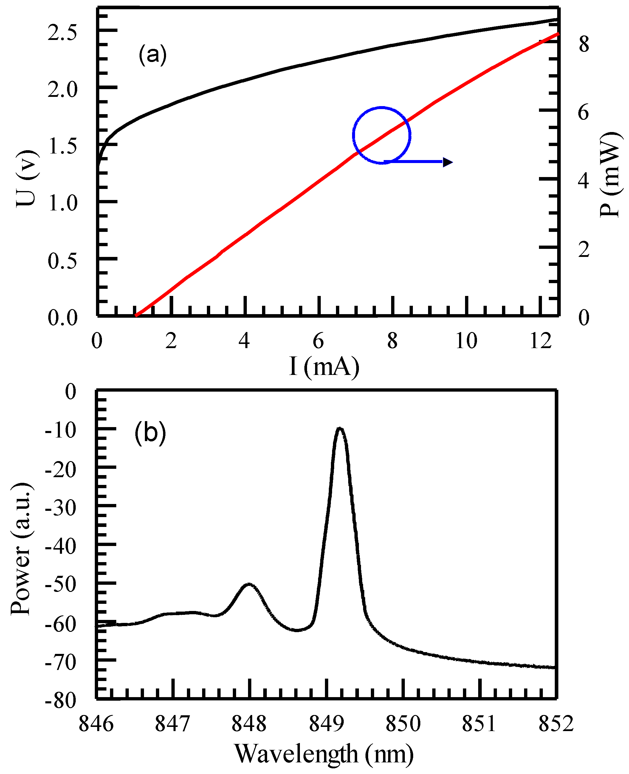
2. VCSEL Design
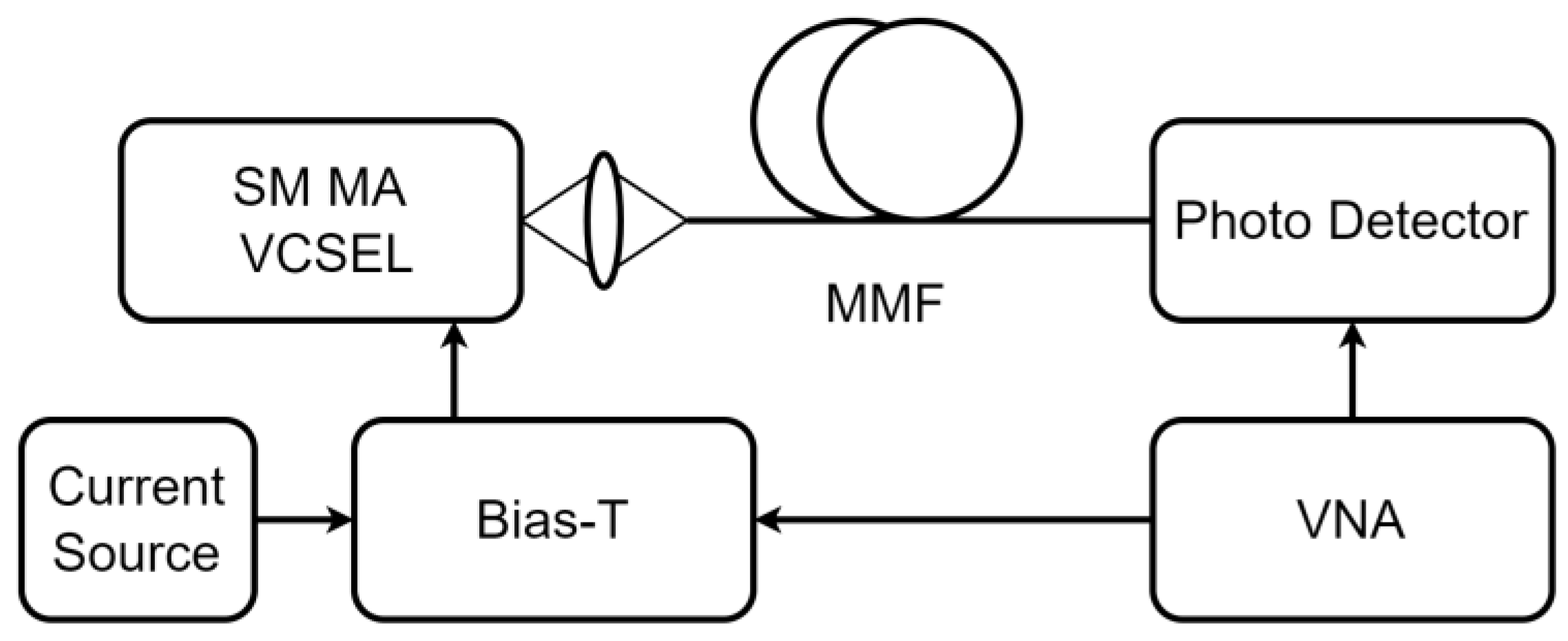
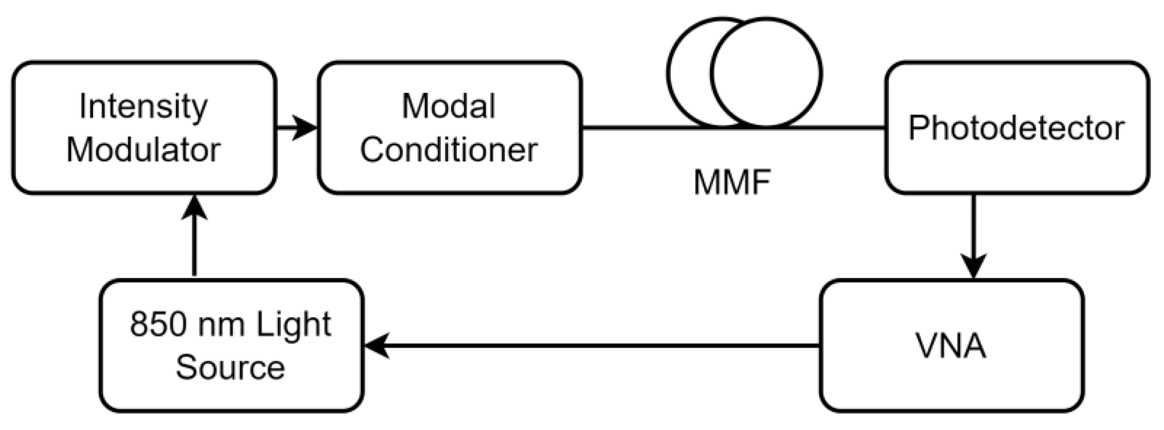
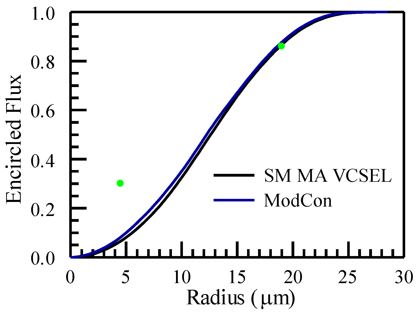
3. Experimental Setup and Launch Condition
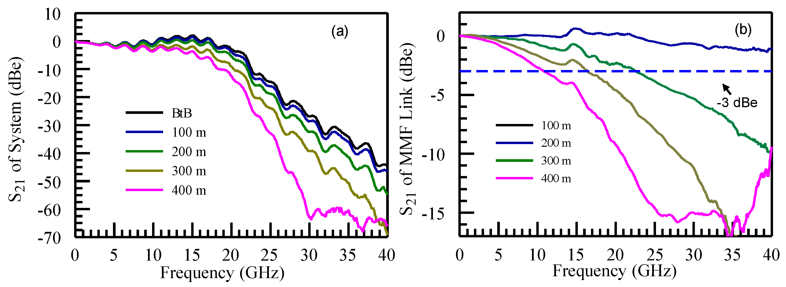
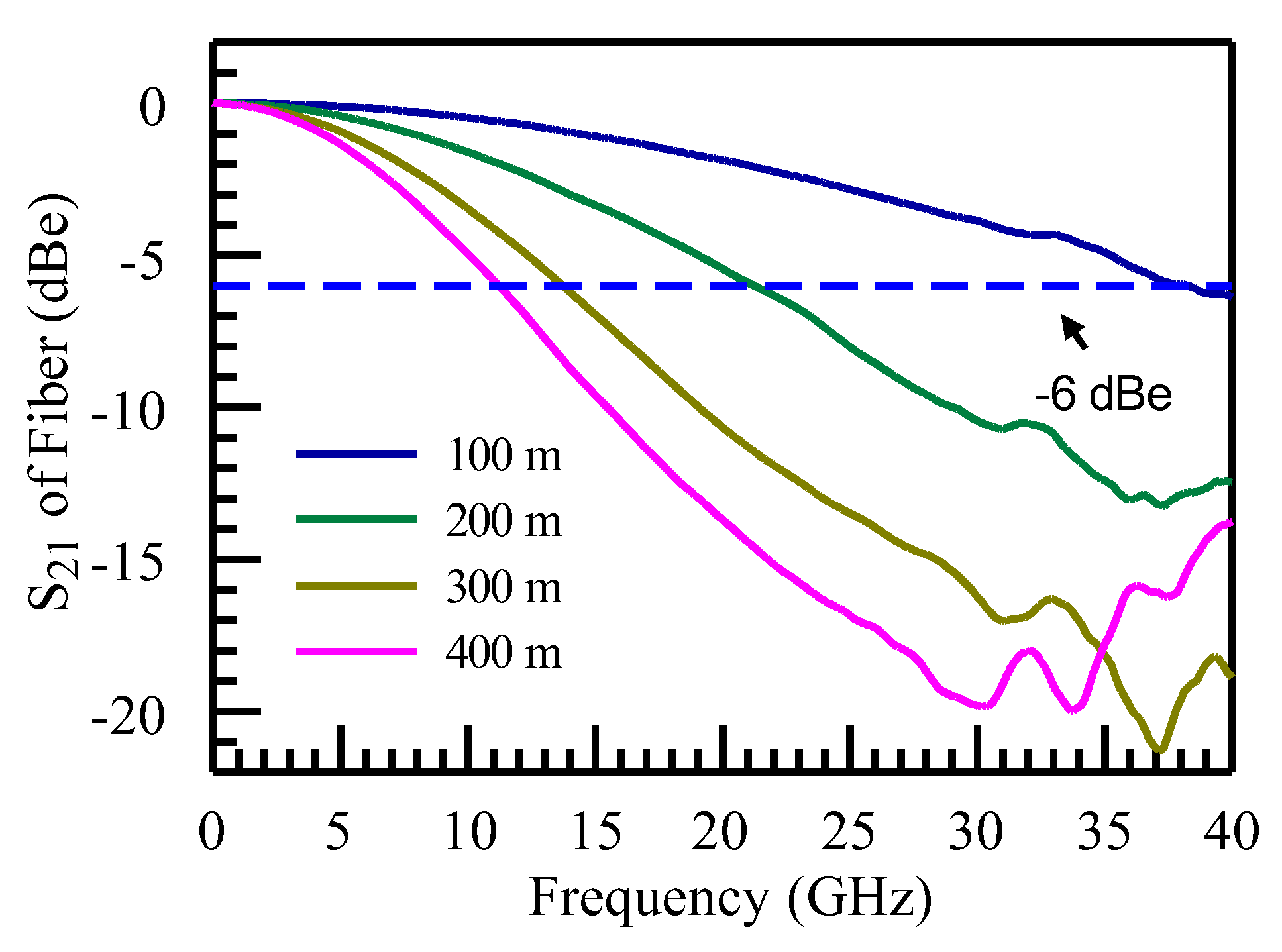
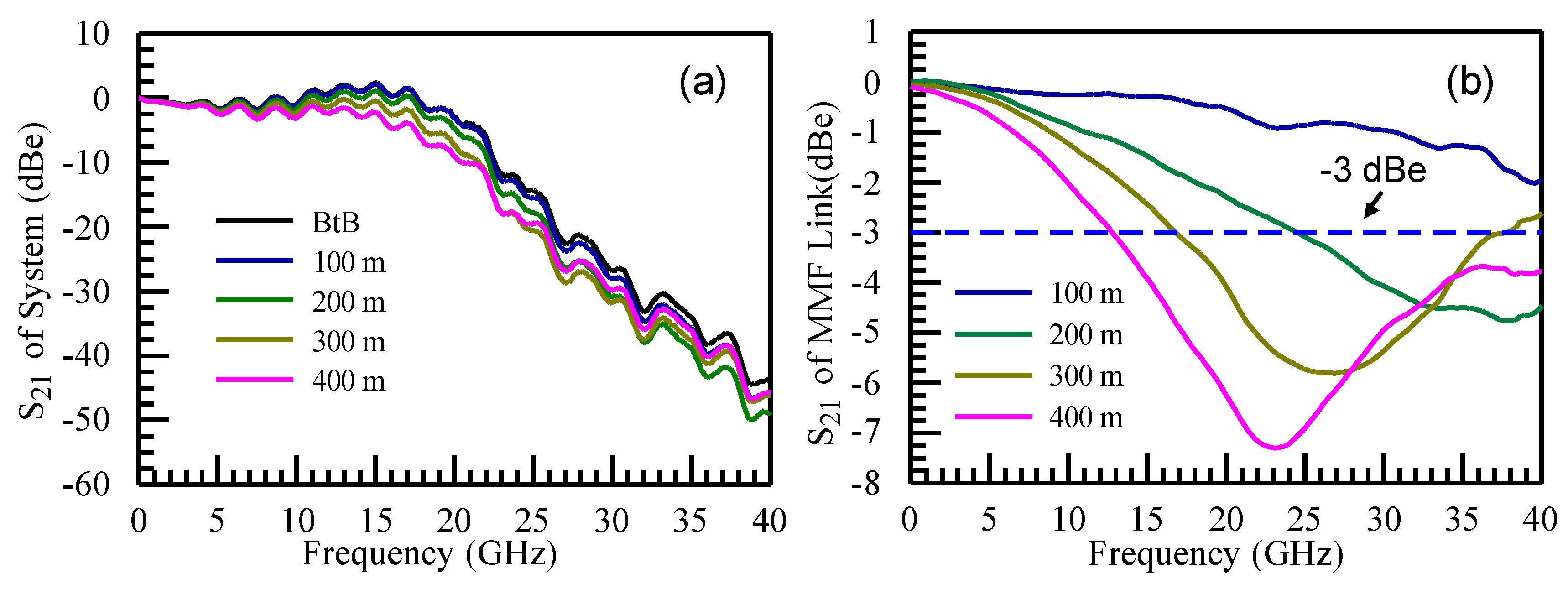
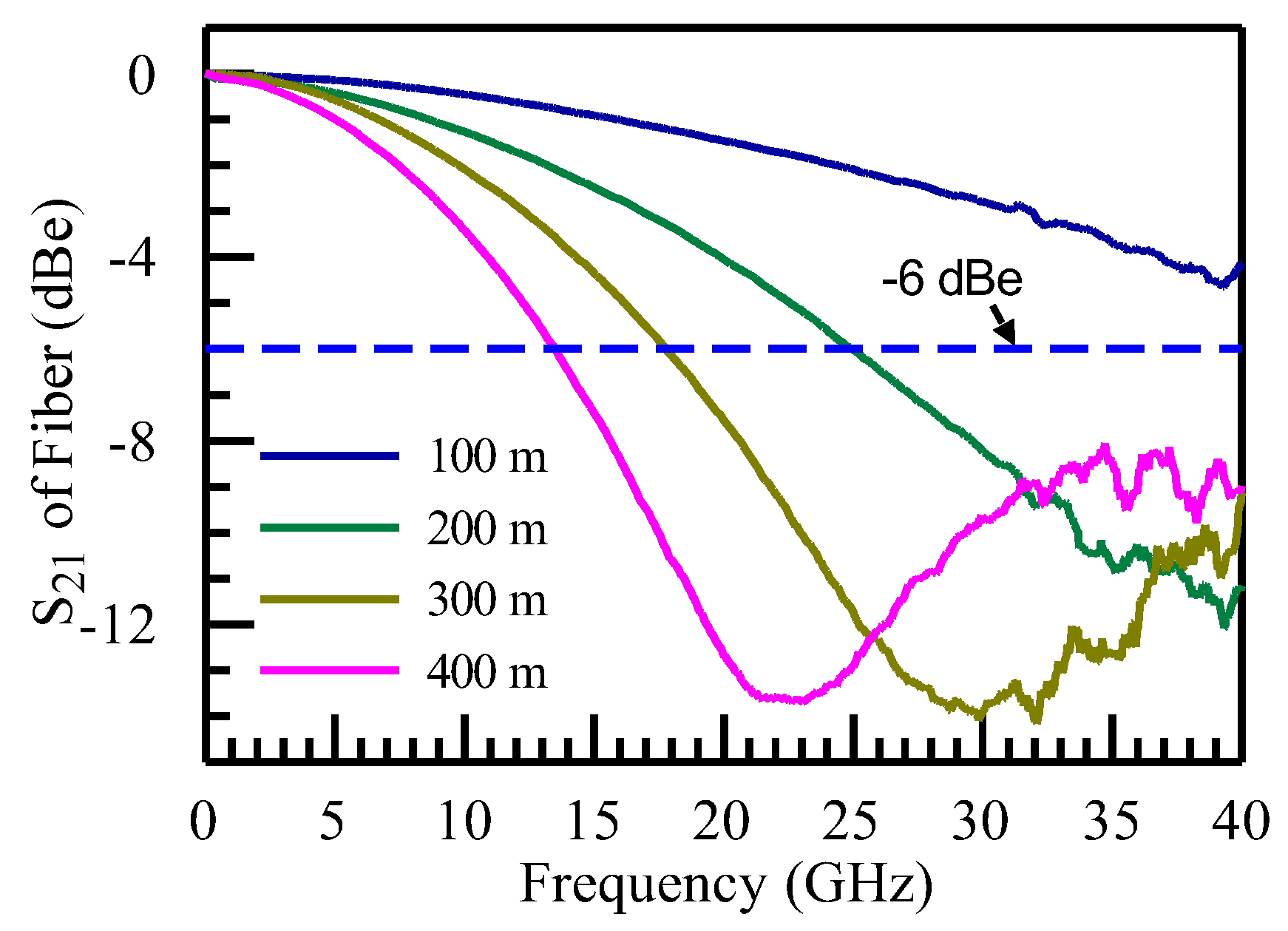
4. Measurement Results of Link Bandwidth and Modal Bandwidth
5. Analysis of Mechanism and Transmission Capability
6. Transmission Result over 200 m MMF
7. Discussion
- Modal bandwidth: The quality of an MMF is characterized by its modal bandwidth or EMB at the operating wavelength. As defined by the standard, the highest grade of MMF is called OM4, which has 4700 MHz·km EMB at 850 nm. It is often desirable to have a higher EMB to support a higher data rate and longer transmission reach. At the link level, the link bandwidth, which has the combined effect of modal bandwidth and bandwidth from laser–CD, is what matters to the transmission. Specifically, link bandwidth is related to modal bandwidth, , and bandwidth from the laser–CD interaction, using the following equation [21],However, when the laser linewidth is high, for example, at 0.6 nm used in the current standard [5], the laser–CD interaction contributes 3.2 GHz·km of bandwidth. Therefore, increasing EMB is helpful but is ultimately limited by the bandwidth from laser–CD interaction if laser linewidth stays high.
- Laser linewidth and laser power: It is well known that reduced VCSEL linewidth can lead to much higher link bandwidth [8,9]. Table 3 illustrates the results of 0.1 nm and 0.6 nm. When SM VCSEL with narrow linewidth is used, the link bandwidth is much higher for the same modal bandwidth when compared to a laser linewidth of 0.6 nm. Another factor is the SM VCSEL can suffer from high current density, which may limit the reliability of the VCSEL. The use of SM MA VCSEL can alleviate such issue by having multiple SM VCSELs on one device, with each contributing lower optical power [10].
- Favorable laser–CD interaction: SM VCSEL can have a favorable interaction between laser chirp and fiber CD [19]. The SM VCSEL from VI-Systems has been reported to have significant chirp (α ~ −3.52) that results in transmission benefit with negative CD in optical fibers. The CD of the MMF at 850 nm is around −100 ps/(nm·km) so the interaction can have a significant effect even at very short lengths as short as 100–200 m.
8. Conclusions
Author Contributions
Funding
Institutional Review Board Statement
Informed Consent Statement
Data Availability Statement
Conflicts of Interest
References
- Michalzik, R. VCSELs: Fundamentals, Technology and Applications of Vertical-Cavity Surface-Emitting Lasers, 2013th ed.; Springer Series in Optical Sciences, 166; Springer: Berlin/Heidelberg, Germany, 2013. [Google Scholar]
- Bottacchi, S. Multi-Gigabit Transmission over Multimode Optical Fibre: Theory and Design Methods for 10GbE Systems; John Wiley & Sons, Ltd.: Hoboken, NJ, USA, 2006. [Google Scholar] [CrossRef]
- Naddod. Available online: https://www.naddod.com/blog/infiniband-network-application-in-dgx-cluster (accessed on 7 December 2024).
- IEEE 802.3db-2022; IEEE Standard for Ethernet—Amendment 3: Physical Layer Specifications and Management Parameters for 100 Gb/s, 200 Gb/s, and 400 Gb/s Operation over Optical Fiber Using 100 Gb/s Signaling. IEEE: Piscataway, NJ, USA, 2022. Available online: https://standards.ieee.org/ieee/802.3db/10283/ (accessed on 7 December 2024).
- Murty, M.V.R.; Wang, J.; Jiang, S.; Dolfi, D.; Wang, T.K.; Vaughan, D.; Feng, Z.-W.; Leong, N.; Sridhara, A.; Joyo, S.T.; et al. Toward 200G per Lane VCSEL-based Multimode Links. In Proceedings of the 2024 Optical Fiber Communications Conference and Exhibition (OFC), San Diego, CA, USA, 24–28 March 2024; pp. 1–3. [Google Scholar] [CrossRef]
- Tirelli, S.; Corti, E.; Duda, E.; Pissis, A.; Hönl, S.; Hoser, M.; Paul, M.; Zibik, E. Lithographic Aperture VCSELs Enabling Beyond 100G Datacom Applications. In Proceedings of the Optical Fiber Communication Conference (OFC), San Diego, CA, USA, 24–28 March 2024; Technical Digest Series; Optica Publishing Group: Washington, DC, USA, 2024. paper M2D.1. [Google Scholar] [CrossRef]
- Murty, M.V.R.; Wang, J.; Jiang, S.; Dolfi, D.; Wang, T.K.; Vaughan, D.; Feng, Z.-W.; Leong, N.; Sridhara, A.; Joyo, S.T.; et al. Advances in VCSEL-Based Multimode Links. In Proceedings of the 2024 IEEE Photonics Society Summer Topicals Meeting Series (SUM), Bridgetown, Barbados, 15–17 July 2024; pp. 1–2. [Google Scholar] [CrossRef]
- Li, M.-J.; Li, K.; Chen, X.; Mishra, S.K.; Juarez, A.A.; Hurley, J.E.; Stone, J.S.; Wang, C.-H.; Cheng, H.-T.; Wu, C.-H.; et al. Single-Mode VCSEL Transmission for Short Reach Communications. J. Light. Technol. 2021, 39, 868–880. [Google Scholar] [CrossRef]
- Ledentsov, N.N.; Lott, J.A.; Kropp, J.-R.; Shchukin, V.A.; Bimberg, D.; Moser, P.; Fiol, G.; Payusov, A.S.; Molin, D.; Kuyt, G.; et al. Progress on single mode VCSELs for data- and tele-communications. In Vertical-Cavity Surface-Emitting Lasers XVI; Proceedings SPIE; SPIE: Bellingham, WA, USA, 2012; Volume 8276, 82760K. [Google Scholar] [CrossRef]
- Chorchos, L.; Ledentsov, N.; Makarov, O.; Shchukin, V.A.; Kalosha, V.; Turkiewicz, J.P.; Ledentsov, N.N. Multi-Aperture High Power 100G Single Mode 850 nm VCSEL for Extended Reach 800G Ethernet. In Proceedings of the 2023 Optical Fiber Communications Conference and Exhibition (OFC), San Diego, CA, USA, 5–9 March 2023; pp. 1–3. [Google Scholar] [CrossRef]
- Stepniak, G.; Lewandowski, A.; Kropp, J.R.; Ledentsov, N.N.; Shchukin, V.A.; Ledentsov, N., Jr.; Schaefer, G.; Agustin, M.; Turkiewicz, J.P. 54 Gbit/s OOK transmission using single–mode VCSEL up to 2.2 km MMF. Electron. Lett. 2016, 52, 633–635. [Google Scholar] [CrossRef]
- Ledentsov, N., Jr.; Makarov, O.; Kon, A.; Kujirai, Y.; Saito, Y.; Titkov, I.; Kropp, J.-R.; Ledentsov, N. Light turning connector optimized for 800G MMF extended reach with the use of Multi Aperture Single Mode 850 nm VCSELs. In Proceedings of the 2024 European Conference on Optical Communication (ECOC), Frankfurt, Germany, 22–26 September 2024; pp. 1–3. [Google Scholar]
- Wang, J.; Ji, Y.; Yang, Z.; Hu, H.; Chen, J.; Li, H.; Li, F.; Li, S.; Kapraun, J.; Shen, C.; et al. 300-m multimode fiber transmission of 106 Gbps PAM-4 using 850 nm high-contrast-grating few-mode VCSELs. In Proceedings of the 2022 European Conference on Optical Communication (ECOC), Basel, Switzerland, 18–22 September 2022; pp. 1–3. [Google Scholar]
- Wu, D.; Yu, X.; Wu, H.; Fu, W.; Feng, M. Single-mode 850 nm VCSELs Demonstrate 96 Gb/s PAM4 OM4 Fiber Link for Extended Reach to 1 km. In Proceedings of the Optical Fiber Communication Conference (OFC), San Diego, CA, USA, 6–10 March 2022; Matsuo, S., Plant, D., Wey, J.S., Fludger, C., Ryf, R., Simeonidou, D., Eds.; Technical Digest Series. Optica Publishing Group: Washington, DC, USA, 2022. paper W2A.7. [Google Scholar] [CrossRef]
- Motaghiannezam, S.M.R.; Tatarczak, A.; Chen, H.; Tatum, J.; Kocot, C. 51.56 Gbps PAM4 Transmission over up to 2.3 km OM4 Fiber using Mode Selective VCSEL. In Proceedings of the Optical Fiber Communication Conference, OSA Technical Digest, Online, 11–15 March 2018; Optica Publishing Group: Washington, DC, USA, 2018. paper M1I.3. [Google Scholar] [CrossRef]
- Chen, X.; Li, K.; Hurley, J.E.; Stone, J.S.; Li, M.-J. Modal bandwidth and single-mode VCSEL transmission capability over multimode fibers. IEEE Photonics Technol. Lett. 2021, 33, 155–158. [Google Scholar] [CrossRef]
- Kim, M.; Kim, B.G.; Bae, S.; Chung, Y.C. 112-Gb/s PAM4 transmission over 1 km of MMF with mode-field matched center-launching in 850-nm band. IEEE Photon. Technol. Lett. 2021, 33, 23–26. [Google Scholar] [CrossRef]
- Castro, J.M.; Pimpinella, R.; Kose, B.; Lane, B. Investigation of the Interaction of Modal and Chromatic Dispersion in VCSEL–MMF Channels. J. Light. Technol. 2012, 30, 2532–2541. [Google Scholar] [CrossRef]
- Chen, X.; Li, K.; Stone, J.S.; Li, M.-J. Enhanced 850-nm SM VCSEL transmission by favorable chirp interaction with fiber dispersion. AIP Adv. 2021, 11, 105104. [Google Scholar] [CrossRef]
- IEC 60793-2-10; Optical Fibres–Part 2-10: Product Specifications—Sectional Specification for Category A1 Multimode Fibres. IEC: Geneva, Switzerland, 2005; Edition 7.0 2022-01.
- IEEE P802.3cm 400 Gb/s over Multimode Fiber Task Force Ad Hoc Web/Teleconference. Available online: https://www.ieee802.org/3/cm/public/adhoc/king_3cm_adhoc_01_062818.pdf (accessed on 8 December 2024).
- Chen, X.; Li, K.; McCool, R.A.; Chen, H.; Dong, H.; Patel, S.M.; Hurley, J.E.; Stone, J.S.; Bickham, S.; Li, M. Feasibility of 25 Gb/s MWDM Transmission over a 15-km G652.D Compliant Fiber for 5G Fronthaul Networks. In Proceedings of the 26th Optoelectronics and Communications Conference, Hong Kong, China, 3–7 July 2021; Wai, P.A., Tam, H., Yu, C., Eds.; OSA Technical Digest. Optica Publishing Group: Washington, DC, USA, 2021. paper T2C.7. [Google Scholar]


| Fiber Length (m) | Modal BW (GHz) | Scaled Modal BW (GHz·km) | Link BW at −3 dBe (GHz) | Link BW at −6 dBe (GHz) |
|---|---|---|---|---|
| 100 | 38.3 | 3.83 | ≫40 | ≫54.8 |
| 200 | 21.2 | 4.25 | 22.5 | 31.4 |
| 300 | 13.7 | 4.12 | 16.4 | 22.3 |
| 400 | 11.3 | 4.50 | 10.8 | 16.3 |
| Fiber Length (m) | Modal BW (GHz) | Scaled Modal BW (GHz·km) | Link BW at −3 dBe (GHz) | Link BW at −6 dBe (GHz) |
|---|---|---|---|---|
| 100 | 45.0 | 4.50 | ≫40 | ≫54.8 |
| 200 | 25.0 | 4.99 | 24.5 | 34.6 |
| 300 | 17.8 | 5.34 | 16.8 | 23.7 |
| 400 | 13.5 | 5.39 | 12.8 | 18.0 |
| Fiber Length (m) | BW (GHz) | Link BW at 0.1 nm Linewidth (GHz) | Link BW at 0.6 nm Linewidth (GHz) |
|---|---|---|---|
| 100 | 47.00 | 33.3 | 19.16 |
| 200 | 23.50 | 16.7 | 9.58 |
| 300 | 15.65 | 11.1 | 6.39 |
| 400 | 11.75 | 8.3 | 4.79 |
Disclaimer/Publisher’s Note: The statements, opinions and data contained in all publications are solely those of the individual author(s) and contributor(s) and not of MDPI and/or the editor(s). MDPI and/or the editor(s) disclaim responsibility for any injury to people or property resulting from any ideas, methods, instructions or products referred to in the content. |
© 2025 by the authors. Licensee MDPI, Basel, Switzerland. This article is an open access article distributed under the terms and conditions of the Creative Commons Attribution (CC BY) license (https://creativecommons.org/licenses/by/4.0/).
Share and Cite
Chen, X.; Ledentsov, N., Jr.; Hurley, J.E.; Makarov, O.Y.; Li, M.-J.; Ledentsov, N. Link Bandwidth and Transmission Capability of Single-Mode Multi-Aperture Vertical-Cavity Surface-Emitting Lasers at 100 G/Lane and 200 G/Lane over Multimode Fibers. Photonics 2025, 12, 147. https://doi.org/10.3390/photonics12020147
Chen X, Ledentsov N Jr., Hurley JE, Makarov OY, Li M-J, Ledentsov N. Link Bandwidth and Transmission Capability of Single-Mode Multi-Aperture Vertical-Cavity Surface-Emitting Lasers at 100 G/Lane and 200 G/Lane over Multimode Fibers. Photonics. 2025; 12(2):147. https://doi.org/10.3390/photonics12020147
Chicago/Turabian StyleChen, Xin, Nikolay Ledentsov, Jr., Jason E. Hurley, Oleg Yu. Makarov, Ming-Jun Li, and Nikolay Ledentsov. 2025. "Link Bandwidth and Transmission Capability of Single-Mode Multi-Aperture Vertical-Cavity Surface-Emitting Lasers at 100 G/Lane and 200 G/Lane over Multimode Fibers" Photonics 12, no. 2: 147. https://doi.org/10.3390/photonics12020147
APA StyleChen, X., Ledentsov, N., Jr., Hurley, J. E., Makarov, O. Y., Li, M.-J., & Ledentsov, N. (2025). Link Bandwidth and Transmission Capability of Single-Mode Multi-Aperture Vertical-Cavity Surface-Emitting Lasers at 100 G/Lane and 200 G/Lane over Multimode Fibers. Photonics, 12(2), 147. https://doi.org/10.3390/photonics12020147