Abstract
Optical frequency combs have been widely used in spectrum analysis, coherent optical communication, and accurate distance measurement. We propose a straightforward method to improve the flatness of optical frequency combs. First, we derived the output of the optical signal for the configuration of a cascaded MZM and two PMs. Second, we identified the parameter value when the flatness was optimal after traversing different parameter spaces. The optimal flatness conditions could be automatically determined from an existing sample dataset by using neural networks and Bayesian optimization, which significantly reduced the calculation cost. Furthermore, a broad spectrum and low power consumption were also achieved. Finally, the generated optical frequency comb signal was divided into eight carriers with 50 GHz intervals, and the optical transmission system was verified by applying a 16-QAM modulation of 40 GBaud/s to each channel. The constellation diagram proved the feasibility of this optical comb generation scheme.
1. Introduction
Communication networks have evolved substantially, advancing from basic frequency and time division multiplexing to today’s sophisticated 5G networks and emerging terabit Ethernet technologies. As people’s demand for communication capacity grows rapidly, the requirements for optical transmission networks are also becoming increasingly stringent [1]. As a multi-carrier laser source, an optical frequency comb exhibits strong coherence between its carriers, which is crucial for high-speed and reliable optical communication systems. Optical frequency comb not only plays a vital role in communication but also has significant applications in gas sensing [2] and spectroscopy. Recent breakthroughs in the under-standing of nonlinear effects and their implementation [3] have advanced the practical development of integrated, packaged nonlinear optical comb systems [4]. Currently, there are three main methods for generating optical frequency combs: using mode-locked lasers, employing nonlinear effects, and utilizing single or cascaded electro-optic modulators. The center frequency and spacing of the comb lines can be adjusted with electro-optic modulators, offering improved flexibility and integration. Recently, the advantages of electro-optic modulators for generating optical frequency combs have become increasingly apparent due to the increased modulation bandwidth and the reduced drive voltage.
The flatness of an optical frequency comb is defined as the difference between its maximum and minimum power levels across the spectrum. A flatter optical frequency comb has a smaller difference between these power levels. Flat optical frequency combs have been widely utilized in various systems, including dense wavelength division multiplexing (DWDM) [5], orthogonal frequency division multiplexing (OFDM) [6], and optical arbitrary waveform generation (OAWG) [7]. Flat electro-optic combs can be generated by combining different phase modulators (PMs) [8,9,10]. Additionally, some methods utilize modulators, such as intensity modulators (IMs) [11,12] and polarization modulators (PolMs) [13,14]. These schemes control the amplitude, phase, frequency, and other degrees of freedom of the modulated signal by various methods to reduce the flatness [15,16]. Masamichi et al. [17] modulated the output light of a continuous wave (CW) laser using sinusoidal electrical signals by a cascaded intensity modulator (IM) and phase modulator (PM) to generate nine sidebands with power differences of less than 3 dB. Xu et al. [18] also implemented a cascaded IM and PM on the lithium niobate on insulator (LNOI) platform, which successfully produced electro-optic combs with 13 lines, a repetition frequency of 31 GHz, and a flatness of better than 1.2 dB. Yu et al. [19] utilized time–frequency mapping to create an on-chip flat-top electro-optic comb based on the LNOI platform. This system included a Mach–Zehnder intensity modulator, a phase modulator, and a chirped Bragg grating, with a power variation of 25 comb lines less than 1 dB and a repetition frequency of 30.135 GHz. Recently, Cui et al. [20] utilized cascaded phase modulators and combined harmonics to generate a 15-line electro-optic comb, where they achieved a flatness of 0.29 dB in simulations and 0.65 dB in experiments. They also employed a dual-parallel Mach–Zehnder modulator (MZM), along with superposed harmonics to create a 13-line electro-optic comb, which exhibited a flatness of 0.58 dB [21]. However, existing schemes still face several challenges. With increasing degrees of freedom, the computational cost of traditional parameter search methods escalates, making the system more complex to control and more sensitive to environmental factors, such as temperature and vibration.
To further optimize the flatness of the electro-optic comb, we propose a more straightforward and efficient method for controlling the system’s degrees of freedom. Based on combining a cascaded MZM and two PMs, we derived the relevant formulas, extracted the system’s key parameters, and utilized an algorithm to identify the parameters that achieved the lowest flatness. We enhanced the program by integrating a Residual Network with a Bayesian optimization algorithm, which resulted in a flatness of 0.5508 dB with 33 comb lines. Additionally, we verified the optical communication transmission of the generated electro-optic comb signal. From this, we extracted eight carrier channels spaced at 50 GHz and applied 16-QAM modulated signals at a rate of 40 Gbaud/s. The excellent transmission results clearly demonstrate the feasibility of this flat electro-optic comb generation scheme.
2. Principles
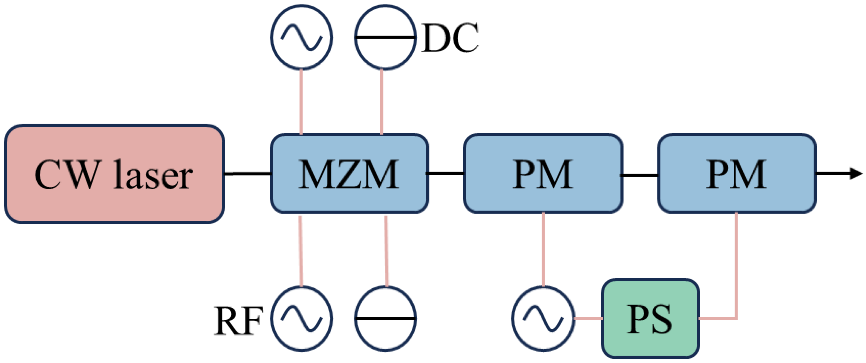
The cascade scheme we implemented is illustrated in Figure 1. The CW light generated by the laser diode first passes through the MZM, followed by two PMs in succession. Finally, the output spectrum is observed with an Optical Spectrum Analyzer (OSA) at the end of the setup. We assume that the input signal generated by the laser is
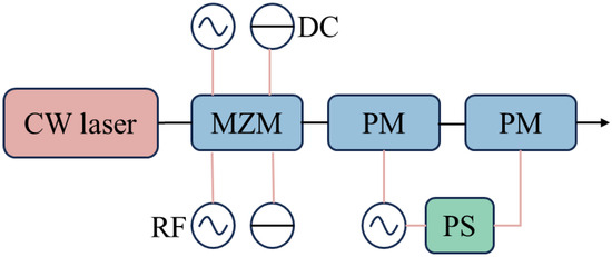
Figure 1.
Scheme of OFC generated by cascaded electro-optic modulators. PS: phase shifter. DC: direct current. RF: radio frequency.
indicates the electric field strength of the input signal. indicates the input signal frequency. When the input optical signal passes through the MZM, the expression of the optical signal is as follows:
where represents the RF signal frequency, represents the direct current (DC) phase difference between the two arms of the MZM (the static phase shift), represents the modulation index of the upper arm of the MZM, represents the modulation index of the lower arm of the MZM, and θ represents the phase difference in RF signal between the upper and lower arms. and represent the RF signal amplitudes of the upper and lower arms. and represent the half-wave voltages of the upper and lower arms. and indicate the bias voltage amplitudes for the upper and lower arms. Additionally, and represent the DC half-wave voltage of the upper and lower arms of the MZM. After the light signal passes through two PMs, the final output signal can be expressed as follows:
The two PMs used in our scheme are identical, and thus, we treated the two PMs in the subsequent cascade as equivalent components, which are represented by the modulation index A3. Since the modulator’s performance remains consistent, applying a voltage to the two PMs separately can be considered equivalent to applying a voltage to a single PM. However, the final modulation index must be divided by two to correspond to each PM. The equation for the modulation index is given by
In this equation, represents the amplitude of the RF signal applied to the PM, while denotes the half-wave voltage of the PM. The expression above clearly shows that the resulting output optical signal consists of a series of harmonics when the CW light passes through the cascaded modulators. The amplitude of each harmonic is associated with the corresponding first-class Bessel function (which depends on the modulation index) and the magnitude of the modulation signal phase.
3. Methods and Results
The magnitude of optical power is proportional to the square of the electric field intensity. Flatness is defined as the difference between the maximum and minimum values of this squared intensity. We explored the ranges of the parameters A1, A2, A3, θ, and ∆φ using an algorithm to determine the optimal parameter values that resulted in the lowest flatness.
Our training code used a Residual Neural Network (ResNet) architecture to learn the mapping of the input parameters A1, A2, A3, ∆φ, and θ to the output parameter flatness. We used the Adam optimizer to help the model escape local minima and find better solutions. Additionally, Bayesian optimization served as a powerful tool for the hyperparameter tuning, which could further enhance the effectiveness of model training. This approach ensured the selection of the optimal combination of hyperparameters, ultimately improving the performance and generalization ability of the final model. We opted for a well-established, lightweight network architecture that maintained accuracy while minimizing the computational complexity. The training cost of the neural network depended on the size of the dataset and various hyperparameters, including the batch size, number of epochs, and learning rate. By combining neural networks with Bayesian optimization, we could effectively accelerate the search process in the parameter space while significantly reducing the computational costs. This innovative approach merges machine learning technology with traditional optimization algorithms, enhancing both the computational efficiency and the accuracy of the optimization results. This method provides an efficient and reliable solution for optimizing complex multi-parameter systems. In this work, we propose an efficient multi-parameter optimization method that combines a ResNet with Bayesian optimization to identify the parameter combination that achieves the lowest flatness in the system. The structure of the neural network is illustrated in Figure 2.
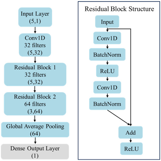
Figure 2.
Scheme of ResNet and Residual Block structure.
Specifically, ResNet serves as a nonlinear mapping model between parameters and the objective function (flatness). Its deep architecture and residual connections address the gradient vanishing problem commonly found in complex multi-parameter systems. This enables the network to capture high-dimensional nonlinear relationships in large-scale parameter systems while reducing the training difficulty.
Following the structure above, the Bayesian optimization utilizes the predicted values and uncertainties of the neural network’s output as the input. It constructs a proxy model based on Gaussian processes to progressively narrow down the optimal solution range for the objective function. The flatness of the system can be obtained through simulation or experimentation. Here, we used the results obtained from the simulation. For each sample, the flatness results were fed back into the neural network model to update its weights and gradually improve its predictive capability. Simultaneously, the proxy model used in the Bayesian optimization was updated to increase the sampling efficiency further.
Compared with traditional methods, such as grid search or Monte Carlo simulations, our approach significantly reduces the number of samples required and the computational cost associated with parameter searches. It offers a practical and universal solution for optimization problems in complex multi-parameter systems. We added more constraints to our calculations, specifically concerning the input voltage, total power, and cascaded configuration of the control modulator. These adjustments aimed to achieve better flatness while also reducing the power consumption.
In particular, we explored the following optimization strategies:
First, we limited the input voltage of each modulator to a maximum of 2 Vπ. This restriction helped prevent nonlinear distortion and excessive modulation depth caused by high voltage, thereby maintaining the stability of the electro-optic comb.
Second, we maintained a constant total input power. In this case, each modulator distributed the power proportionally to avoid uneven optical frequency combs due to power fluctuations. This strategy of keeping the total power constant stabilized the energy distribution of the output spectrum, thereby improving the consistency of each frequency component.
By comparing the flatness of these constraints on the optical frequency comb, we could determine the best restriction scheme that balanced minimizing the power fluctuations, reducing the nonlinear distortion, and providing a suitable modulation depth.
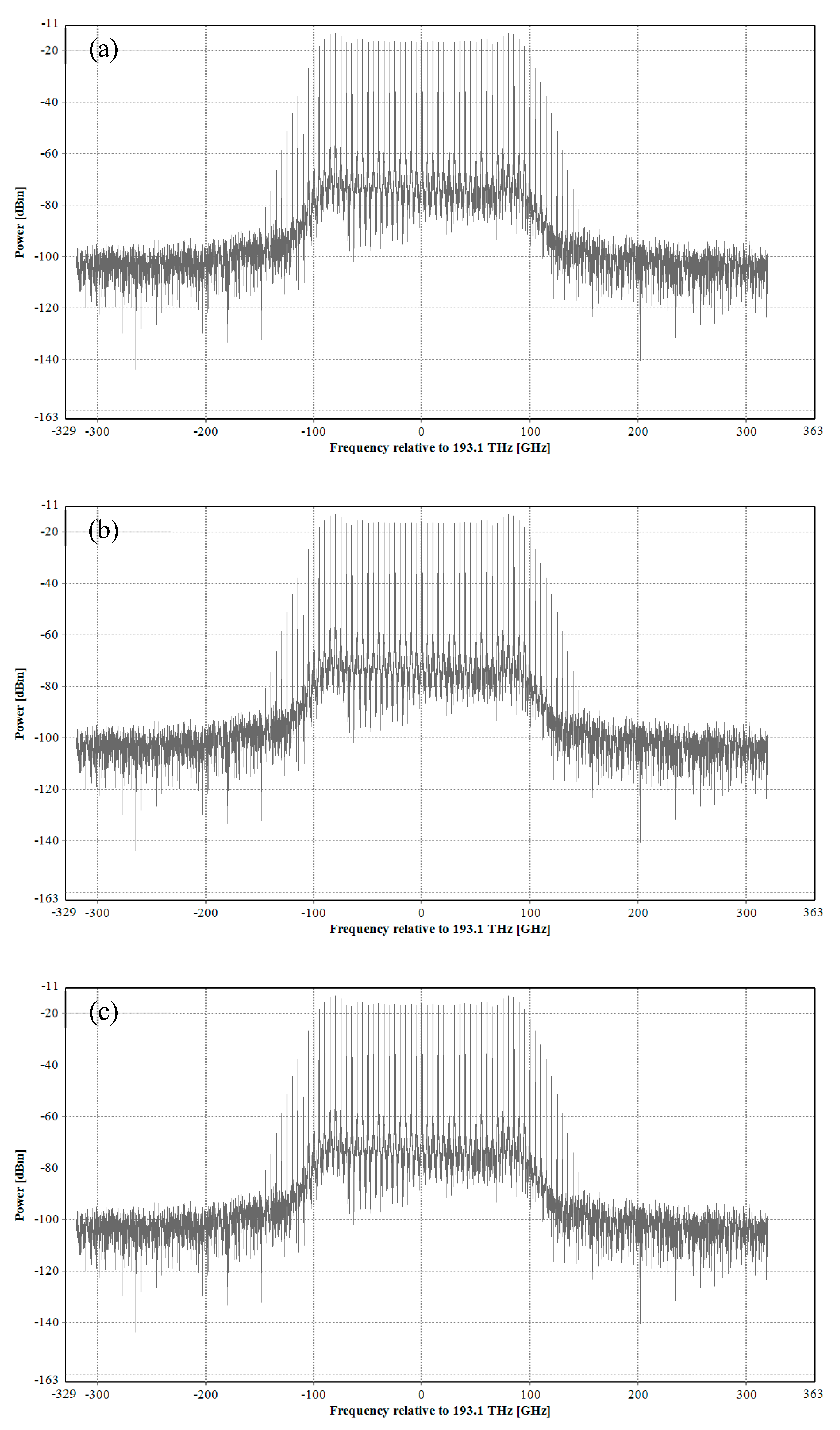
In the simulation system, the MZM’s 3 V and the extinction ratio was set as 45 dB. The of both phase modulators was 3 V. Considering the first restriction condition—that the input of each modulator did not exceed 2—we conducted calculations for configurations with 33, 31, and 29 comb lines. The results reveal that the flatness for the configuration with 33 comb lines was 3.2496 dB. For the 31-comb-line configuration, the flatness improved to 2.7472 dB. The configuration with 29 comb lines demonstrated an even better flatness of 1.3692 dB. These results indicate that the flatness improved as the number of comb lines decreased. The figure obtained from the simulation, which illustrates these findings, is presented in Figure 3. The flatness verification for 33, 31, and 29 comb lines is displayed from top to bottom.
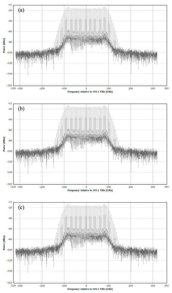
Figure 3.
Simulation results for the optical frequency comb with the input voltage for each modulator not exceeding 2 Vπ. (a) The result for 33 comb lines. (b) The result for 31 comb lines. (c) The result for 29 comb lines.
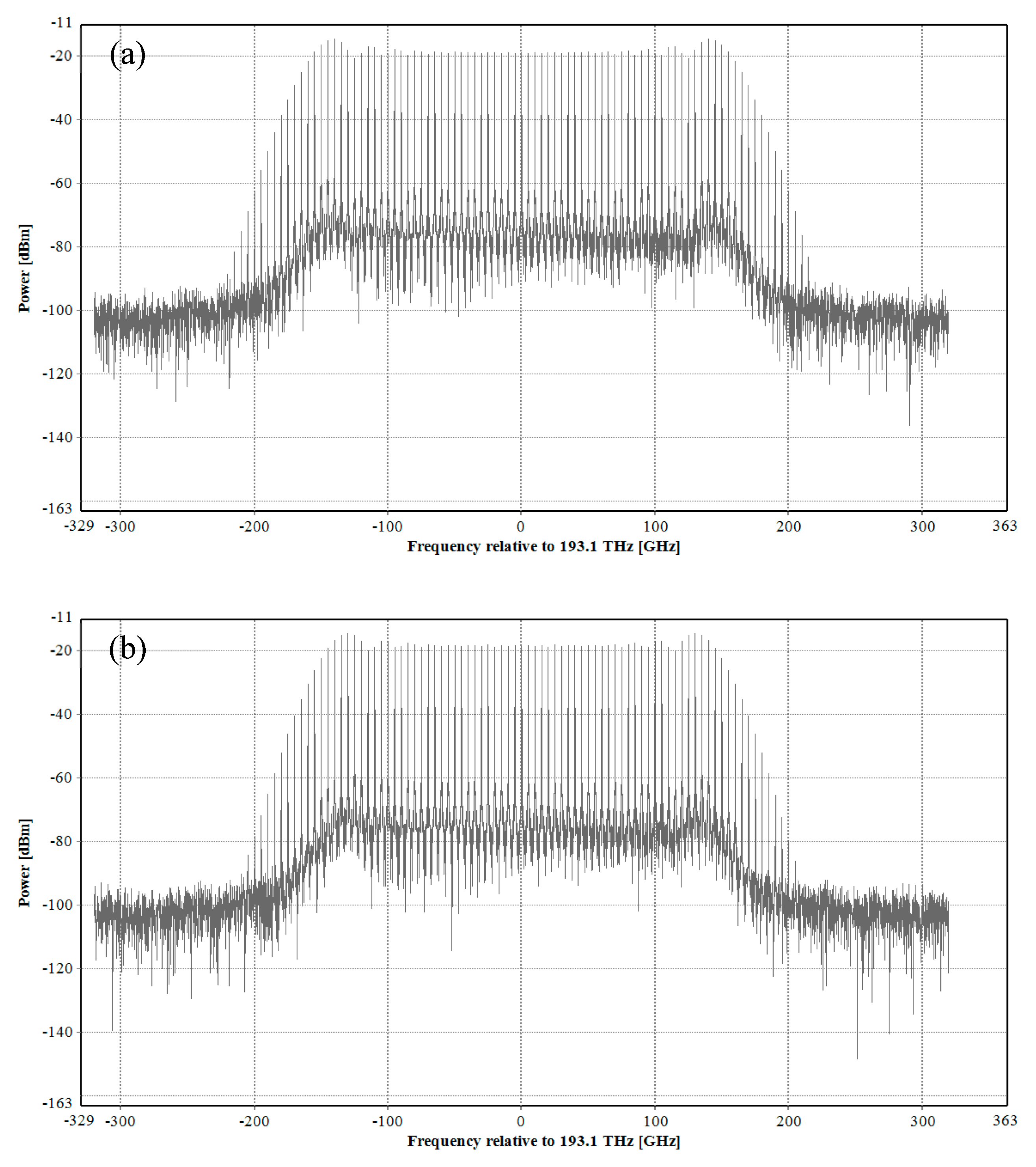
Considering the second restriction condition, we assumed the total input power remained constant. Since the modulation index is proportional to the strength of the input signal, we directly set the square sum of several modulation indices to a fixed value during the optimization process. This approach is equivalent to maintaining a constant total input power. By not constraining each modulator input to a maximum of 2 Vπ, we observed an improvement in the flatness. The flatness of 35 comb lines was measured as 0.7592 dB, while for 33 comb lines, it reached 0.6964 dB. The optimization results were validated through simulation, as shown in Figure 4, which depicts the configurations for 35 and 33 comb lines arranged from top to bottom.
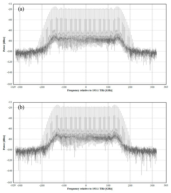
Figure 4.
Simulation results for the optical frequency comb, where the total input power remained constant. (a) The result for 35 comb lines. (b) The result for 33 comb lines.
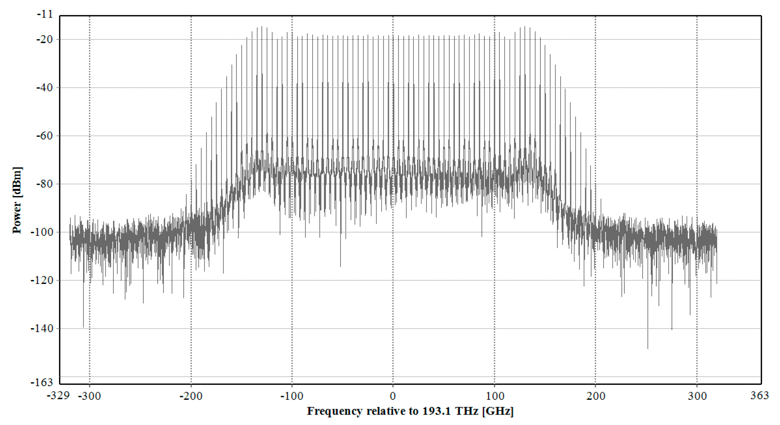
Table 1 presents the optimized parameter values obtained from the neural network. When comparing the above schemes, we obtained the best result of 33 comb lines, with a flatness of 0.5508 dB, and the simulation verification is illustrated in Figure 5.

Table 1.
The parameter values optimized by the neural network.
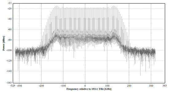
Figure 5.
Simulation result for the optical frequency comb with an optimal flatness of 0.5508 dB.
To validate the application potential of our generated electro-optic comb in fiber coherent transmission, we conducted an eight-channel, 48-Gbaud, 16-quadrature amplitude modulation (QAM) transmission simulation, whose system link structure is shown in Figure 6.
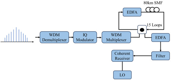
Figure 6.
Scheme of the optical transmission system.
After generating the electro-optic comb using the cascaded modulators designed in the previous stage, we used a wavelength division multiplexing (WDM) demultiplexer to divide the spectrum into eight independent optical carriers, each spaced 50 GHz apart. This uniform frequency interval between the optical carriers ensured they met the requirements for subsequent modulation. These separated optical carriers were modulated and transmitted as information-bearing signals in the following steps. IQ modulation processed each optical carrier to apply a 16-QAM modulation. This modulation type allows for transmitting more data simultaneously on the same carrier, enhancing the signal’s spectrum utilization. After modulation, we combined the signal using a multiplexer and transmitted it through a 1200 km single-mode fiber. Next, the signal was amplified by an Erbium-Doped Fiber Amplifier (EDFA), and then the carrier signal of each channel was filtered out using a tunable filter. Each optical carrier was mixed with a local oscillator light source at the receiver to demodulate the input signal. A coherent receiver converted the mixed signal into an electrical signal to enable the transition from the optical to the electrical domain. Ultimately, the electrical signal was sampled and processed through digital signal processing (DSP) operations to recover the transmitted data information.
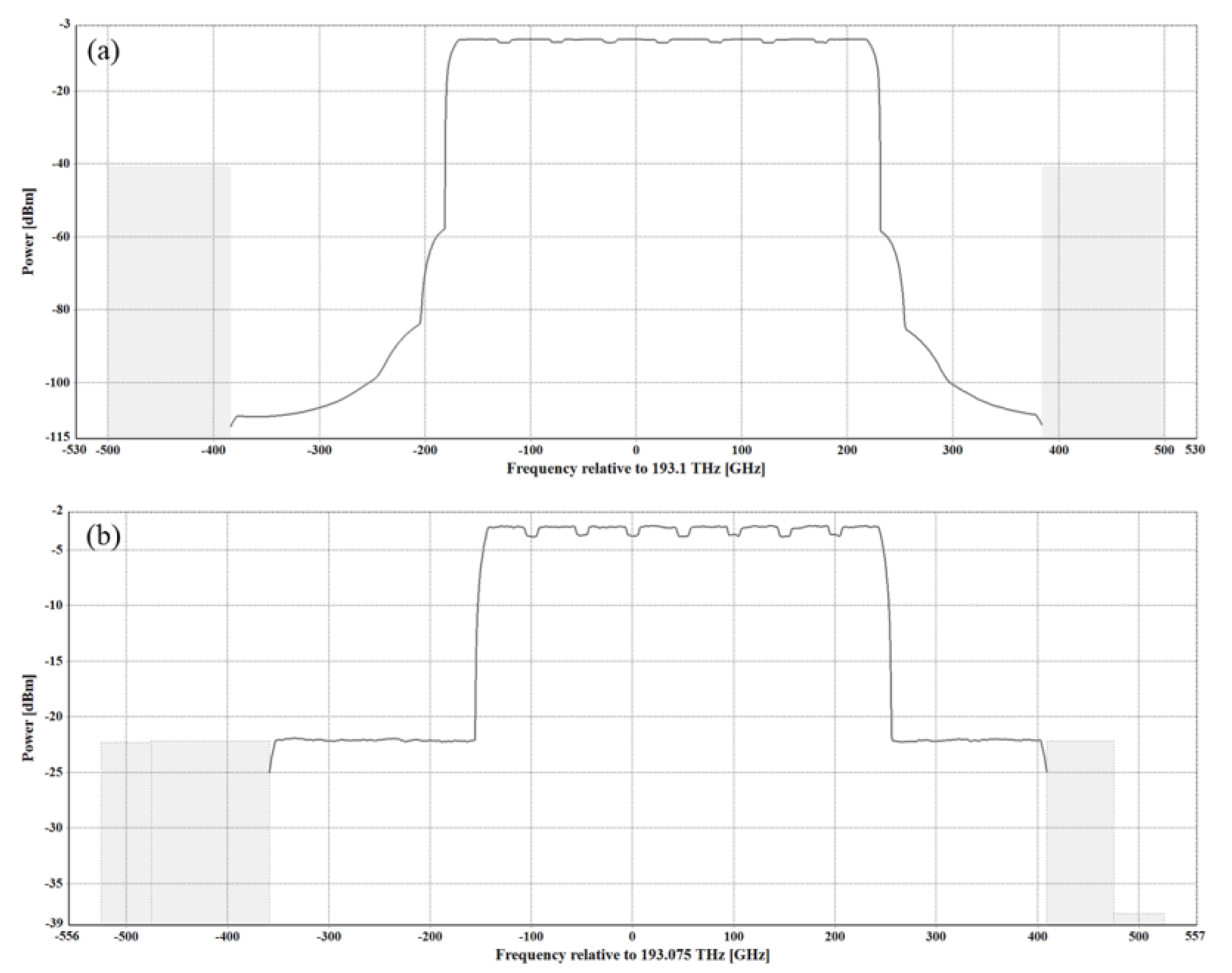
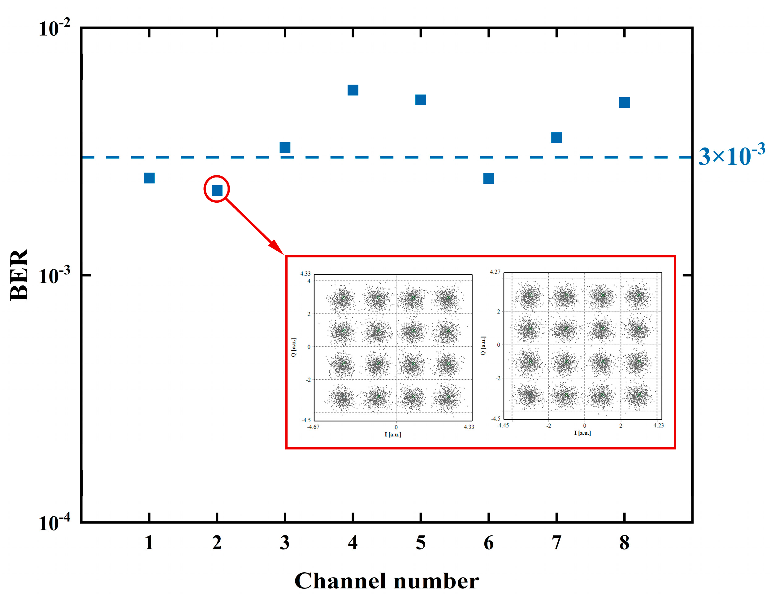
Figure 7 displays the optical spectrum before and after the fiber transmission, where we can observe that the channels appear flat. Figure 8 displays the bit error rate (BER) for the eight channels after the demodulation, along with the constellation diagram for the channel operating at a frequency of 193.15 THz. The results indicate that the BER values of the eight channels were similar. The inset shows precise and closely clustered constellation point distributions. This indicates that the optical signal retained good phase and amplitude characteristics during the transmission, which resulted in a low bit error rate and high transmission quality. Consequently, the signal integrity and stability of the system were effectively verified.

Figure 7.
The optical spectrum (a) before and (b) after the fiber transmission (resolution is 0.1 nm).
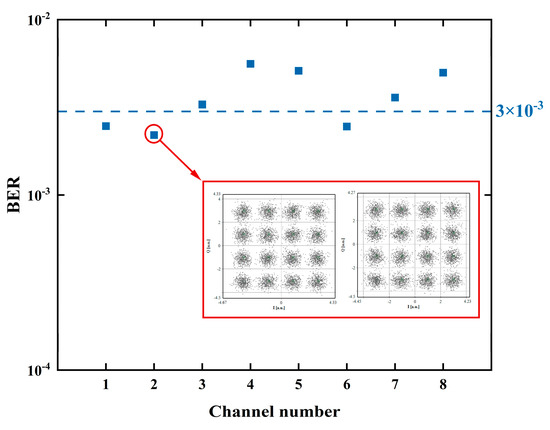
Figure 8.
The result of the bit error rate (BER) for the eight channels. The inset shows the constellation diagram for the channel at 193.15 THz.
4. Conclusions
In this work, we presented a method to generate flat optical frequency combs using an MZM and two PMs. Our theoretical framework explains how different parameters influence the cascaded modulators’ output. We combined this framework with a ResNet and Bayesian optimization algorithm to efficiently identify optimal parameters for maximum flatness, reducing the computational costs compared with the traditional grid search method. Ultimately, we achieved a minimum flatness of 0.5508 dB. The performance of the generated signal in the optical communication system’s transmission experiment demonstrated that this technology offers an efficient carrier generation scheme for next-generation optical networks. Our method serves as a general optimization technique for multi-degree-of-freedom systems, simplifies the complex derivation process, lowers the computational cost of parameter searching, and offers a valuable support tool for generating high flatness electro-optic frequency combs.
Author Contributions
Conceptualization, W.L. and B.Z.; methodology, W.L.; software, B.Z.; validation, W.L. and B.Z.; formal analysis, K.C.; investigation, H.Y.; resources, X.Z.; data curation, J.C.; writing—original draft preparation, W.L.; writing—review and editing, B.Z.; supervision, Y.L.; project administration, Y.L.; funding acquisition, Y.L. All authors have read and agreed to the published version of the manuscript.
Funding
This research was funded by the National Key Research and Development Program of China (2023YFB2805202).
Institutional Review Board Statement
Not applicable.
Informed Consent Statement
Not applicable.
Data Availability Statement
The data presented in this study may be available from the corresponding author upon reasonable request.
Conflicts of Interest
The authors declare no conflicts of interest.
References
- Wooten, E.L.; Kissa, K.M.; Yi-Yan, A.; Lafaw, D.A.; Hallemeier, P.F.; Maack, D.; Attanasio, D.V.; Fritz, D.J.; McBrien, G.J.; Bossi, D.E. A review of lithium niobate modulators for fiber-optic communications systems. IEEE J. Sel. Top. Quantum Electron. 2000, 6, 69–82. [Google Scholar] [CrossRef]
- An, N.; Li, Y.; Zhang, H.; Liang, Y.; Tan, T.; Guo, Y.; Liu, Z.; Liu, M.; Guo, Y.; Wu, Y.; et al. Brillouin lasers in a graphene microresonator for multispecies and individual gas molecule detection. APL Photonics 2023, 8, 100801. [Google Scholar] [CrossRef]
- Zhai, K.; Zhang, X.; Wang, W.; Chen, B.; Jin, Y.; Du, X.; Liu, Y.; Cui, J.; Li, Q.; Zhou, H.; et al. Photonic-Assisted Microwave Harmonic Down-Conversion Based on Four-Wave Mixing in a Silicon Integrated Waveguide Doped with Reverse-Biased PiN Junction. J. Light Technol. 2023, 41, 7268–7275. [Google Scholar] [CrossRef]
- Zhao, G.; Özdemir, Ş.K.; Wang, T.; Xu, L.; King, E.; Long, G.L.; Yang, L. Raman lasing and Fano lineshapes in a packaged fiber-coupled whispering-gallery-mode microresonator. Sci. Bull. 2017, 62, 875–878. [Google Scholar] [CrossRef] [PubMed]
- Bennett, S.; Cai, B.; Burr, E.; Gough, O.; Seeds, A.J. 1.8-THz bandwidth, zero-frequency error, tunable optical comb generator for DWDM applications. IEEE Photonics Technol. Lett. 1999, 11, 551–553. [Google Scholar] [CrossRef]
- Fontaine, N.K.; Geisler, D.J.; Scott, R.P.; He, T.; Heritage, J.P.; Yoo, S.J.B. Demonstration of high-fidelity dynamic optical arbitrary waveform generation. Opt. Express 2010, 18, 22988–22995. [Google Scholar] [CrossRef] [PubMed]
- Jiang, Z.; Huang, C.B.; Leaird, D.E.; Weiner, A.M. Optical arbitrary waveform processing of more than 100 spectral comb lines. Nat. Photonics 2007, 1, 463–467. [Google Scholar] [CrossRef]
- Ozharar, S.; Quinlan, F.; Ozdur, I.; Gee, S.; Delfyett, P.J. Ultraflat optical comb generation by phase-only modulation of continuous-wave light. IEEE Photonics Technol. Lett. 2007, 20, 36–38. [Google Scholar] [CrossRef]
- Zhang, J.; Yu, J.; Chi, N.; Dong, Z.; Li, X.; Shao, Y.; Yu, J.; Tao, L. Flattened comb generation using only phase modulators driven by fundamental frequency sinusoidal sources with small frequency offset. Opt. Lett. 2013, 38, 552–554. [Google Scholar]
- Wu, R.; Supradeepa, V.R.; Long, C.M.; Leaird, D.E.; Weiner, A.M. Generation of very flat optical frequency combs from continuous-wave lasers using cascaded intensity and phase modulators driven by tailored radio frequency waveforms. Opt. Lett. 2010, 35, 3234–3236. [Google Scholar] [CrossRef]
- Dou, Y.; Zhang, H.; Yao, M. Generation of flat optical-frequency comb using cascaded intensity and phase modulators. IEEE Photonics Technol. Lett. 2012, 24, 727–729. [Google Scholar] [CrossRef]
- Soto, M.A.; Alem, M.; Shoaie, M.A.; Vedadi, A.; Brès, C.-S.; Thévenaz, L.; Schneider, T. Optical sinc-shaped Nyquist pulses of exceptional quality. Nat. Commun. 2013, 4, 2898. [Google Scholar] [CrossRef] [PubMed]
- Chen, C.; He, C.; Zhu, D.; Guo, R.; Zhang, F.; Pan, S. Generation of a flat optical frequency comb based on a cascaded polarization modulator and phase modulator. Opt. Lett. 2013, 38, 3137–3139. [Google Scholar] [CrossRef]
- Chen, C.; Zhang, F.; Pan, S. Generation of seven-line optical frequency comb based on a single polarization modulator. IEEE Photonics Technol. Lett. 2013, 25, 2164–2166. [Google Scholar] [CrossRef]
- Buscaino, B.; Zhang, M.; Lončar, M.; Kahn, J.M. Design of efficient resonator-enhanced electro-optic frequency comb generators. J. Light Technol. 2020, 38, 1400–1413. [Google Scholar] [CrossRef]
- Torres-Company, V.; Lancis, J.; Andres, P. Lossless equalization of frequency combs. Opt. Lett. 2008, 33, 1822–1824. [Google Scholar] [CrossRef]
- Fujiwara, M.; Teshima, M.; Kani, J.; Suzuki, H.; Takachio, N.; Iwatsuki, K. Optical carrier supply module using flattened optical multicarrier generation based on sinusoidal amplitude and phase hybrid modulation. J. Light Technol. 2003, 21, 2705. [Google Scholar] [CrossRef]
- Xu, M.; He, M.; Zhu, Y.; Yu, S.; Cai, X. Flat optical frequency comb generator based on integrated lithium niobate modulators. J. Light Technol. 2022, 40, 339–345. [Google Scholar] [CrossRef]
- Yu, M.; David, B.I.; Cheng, R.; Reimer, C.; Kharel, P.; He, L.; Shao, L.; Zhu, D.; Hu, Y.; Grant, H.R.; et al. Integrated femtosecond pulse generator on thin-film lithium niobate. Nature 2022, 612, 252–258. [Google Scholar] [CrossRef]
- Cui, Y.; Wang, Z.; Xu, Y.; Jiang, Y.; Yu, J.; Huang, Z. Generation of flat optical frequency comb using cascaded PMs with combined harmonics. IEEE Photonics Technol. Lett. 2022, 34, 490–493. [Google Scholar] [CrossRef]
- Cui, Y.; Wang, Z.; Zuo, X.; Xu, Y.; Jiang, Y.; Yu, J.; Huang, Z. Flat optical frequency comb generation by using one DPMZM and superposed harmonics. Opt. Commun. 2023, 531, 129223. [Google Scholar] [CrossRef]


Disclaimer/Publisher’s Note: The statements, opinions and data contained in all publications are solely those of the individual author(s) and contributor(s) and not of MDPI and/or the editor(s). MDPI and/or the editor(s) disclaim responsibility for any injury to people or property resulting from any ideas, methods, instructions or products referred to in the content. |
© 2025 by the authors. Licensee MDPI, Basel, Switzerland. This article is an open access article distributed under the terms and conditions of the Creative Commons Attribution (CC BY) license (https://creativecommons.org/licenses/by/4.0/).