Review

Recent Advances in Integrated Vibration Sensing and Communication in Digital Subcarrier Multiplexing Systems

1
Pengcheng Laboratory, Shenzhen 518000, China
2
School of Integrated Circuits, Harbin Institute of Technology, Shenzhen 518055, China
*
Authors to whom correspondence should be addressed.
Photonics 2025, 12(3), 290; https://doi.org/10.3390/photonics12030290
Submission received: 14 February 2025 / Revised: 10 March 2025 / Accepted: 19 March 2025 / Published: 20 March 2025
(This article belongs to the Special Issue Photonics: 10th Anniversary)

Abstract

:
Digital subcarrier multiplexing (DSCM) systems offer flexibility and software configurability, making them promising for point-to-multipoint (P2MP) communications. Meanwhile, DSCM systems exhibit enhanced communication damage tolerance and capabilities for damage monitoring and compensation. These capabilities include tolerance to equalized enhanced phase noise (EEPN) and high-speed Polarization State (SOP) tracking. The subcarrier intervals in DSCM systems naturally allow the insertion of pilot or training sequences. This facilitates enhanced communication functionality and integrated sensing capabilities. This review article summarizes the principles and schemes of integrated communication and sensing in DSCM systems. It analyzes performance in communication enhancement and sensing integration. Finally, it discusses unresolved technical challenges and future technological prospects.

1. Introduction

The rapid advancement of fiber-optic communication systems has revolutionized modern telecommunication networks, offering unparalleled data transmission speed and reliability [1,2]. As these systems continue to expand in scale and complexity, the need for real-time monitoring of physical environmental conditions, such as vibrations, is becoming increasingly critical [3,4,5,6]. This necessity has driven the development of integrated sensing and communication (ISAC) technologies in fiber optics, which aim to seamlessly combine the functionalities of communication and sensing within fiber infrastructure, as shown in Figure 1. By leveraging existing communication systems for environmental monitoring, ISAC can enhance the efficiency of network operation and maintenance and reduce costs [3,4].
The ISAC technology in optical fibers has primarily followed two technical routes. The first category of schemes involves embedding sensing signals into the communication signals of optical fiber, utilizing optical back-scattering to achieve vibration sensing [5,7,8,9,10]. The second category of schemes uses communication digital signal processing (DSP) modules to extract sensing information from the forward-transmitted optical carrier by analyzing parameters such as state of polarization (SOP) [11,12,13,14,15,16,17] and phase [4,18,19,20].
The ISAC technology in fiber optics based on back-scattering combines the traditional optical time-domain reflectometer (OTDR) with fiber communication technology for sensing applications. The authors in [7] utilized two optical ports of deployed passive optical networks for sensing while employing the other ports for communication. They achieved vibration monitoring of structural buildings by detecting the phase of back-scattered light and investigated the impact of 1 × 4 and 1 × 16 splitters on vibration monitoring performance [7]. The authors in [8] proposed a novel approach by linearly modulating the carrier frequency in four-level pulse amplitude modulation (PAM-4) signals based on dimension multiplexing for vibration sensing. By detecting back-scattered Rayleigh light, the scheme successfully achieved a spatial resolution of 4 m and demonstrated that this scheme effectively suppresses nonlinear effects in fibers and enhances communication quality [8]. Inserting linear frequency modulation (LFM) signals into the roll-off band of coherent communication signals can achieve integrated communication and back-scattering-based sensing [9]. By integrating the sensing signals within the signal roll-off band, this scheme significantly improved spectral efficiency. Furthermore, through alternating sensing using LFM signals with varying center frequencies, the influence of fading on sensing was minimized, achieving sub-meter level localization accuracy [9]. In 2024, researchers from Nokia Bell Labs demonstrated back-scattering sensing for underwater vibration monitoring. To ensure compatibility with fiber amplifiers, the researchers employed fiber Bragg gratings to realize fiber loops, enabling reflection-based sensing in links containing erbium-doped optical fiber amplifiers (EDFAs) [10]. The sensing schemes based on back-scattering can achieve high spatial resolution, enabling precise localization of vibrations. However, these schemes face challenges in long-distance sensing and requires additional sensing receivers, making it difficult for integration and implementation.
The forward-SOP-based ISAC technology in fiber optics primarily leverages the birefringence effect of optical fibers. When strain is applied to the fiber, it induces a rotation around the optic axis of the birefringence, which results in changes to the SOP of the received optical signals [11]. By monitoring these SOP variations, the vibration perception capability can be enabled. The authors in [12] utilized the taps of a multi-in and multi-out (MIMO) filter used for polarization demultiplexing to calculate the variations in Stokes parameters, thereby achieving forward-SOP-based sensing. They further employed a robotic arm to simulate four types of external disturbances and used machine learning to classify events [12]. Through the DSP module of the coherent receiver, it was possible to utilize changes in SOP to achieve sensing of sea waves [13], earthquakes [13,14], lightning [21], and winds [15]. The authors in [17] demonstrated that SOP-based sensing signals were correlated with the sensing signals detected by OTDR. For vibration localization, in our previous work, we proposed a unidirectional transmission vibration localization scheme based on SOP and chromatic dispersion [16]. Although sensing based on SOP can be fully compatible with existing coherent DSP algorithms, MIMO requires iteration and has difficulties with high-speed SOP variation tracking, limiting its capability for high-frequency detection. In forward phase-based sensing, fiber deformation alters the optical path length, causing fluctuations in the carrier phase estimated by the carrier phase estimation (CPE) module. This variation enables the detection of vibrations through the carrier phase monitoring. By utilizing the carrier phase recovery module of existing coherent optical communication systems, integrated communication and forward phase-based sensing functions can be achieved [4,18]. However, phase-based sensing schemes are susceptible to laser frequency offset and phase noise, necessitating narrow linewidth lasers (NLLs) to suppress the sensing background noise. Dynamic frequency offset estimation (FOE) based on data blocks can compensate for the frequency drift of commercial external cavity lasers (ECLs) [19,20], but the accuracy is restricted, which hinders the detection of low-frequency vibrations.
In the era of rapidly increasing communication rates, digital subcarrier multiplexing (DSCM) systems are gaining increasing popularity due to their software programmability [22] and tolerance to impairments [23] and nonlinear effects [23,24]. Furthermore, in the carrier intervals of DSCM systems, various specially designed pilots can be inserted to improve communication system performance. For example, by inserting the fractional-order-Fourier-transform-direct-current (FrFT-DC) pilot into the subcarrier interval, FOE and timing recovery can be achieved [25,26]. In our previous work, the frequency-domain pilot tones (FPTs) were inserted into the subcarrier intervals for carrier phase recovery [27], polarization multiplexing [27], polarization-dependent loss compensation [28], and transceiver impairment compensation [29]. These specially designed pilots not only enhance communication system performance but also enable sensing capabilities. Since FrFT-DC pilots carry both time-domain and frequency-domain information, they can be utilized for vibration sensing based on back-scattering [30,31,32,33]. The multiple carrier intervals allow the insertion of multiple FrFT-DC pilots, effectively preventing signal fading [33]. The FPTs can carry phase and polarization information; in our previous work, the FPTs were used for integrated DSCM communication and sensing based on forward phase [34,35] and forward SOP [36]. Due to the ability of FPTs to enhance carrier recovery accuracy and robustness, they effectively improve the sensing signal-to-noise ratio under commercial ECL conditions [34,35]. Additionally, since SOP tracking based on FPTs does not require iteration, it enables high-speed monitoring of fast SOP variations [36].
In this paper, we review the integrated communication and sensing technology solutions in DSCM systems based on FrFT-DC pilots and FPTs. In Section 3, we revisit the principles of FOE and timing recovery using the FrFT-DC pilots [25,26], analyzing the spatial resolution and sensing sensitivity of back-scattering-based sensing using the FrFT-DC pilot [32]. In Section 4, we review the principles of carrier recovery and polarization demultiplexing based on FPTs, investigating the improvement in sensing signal-to-noise ratio for phase-based sensing induced by FPTs [34]. Furthermore, we review an adaptive vibration-induced phase extraction scheme using a Wiener filter (WF) [35]. Additionally, we analyze the high-speed SOP tracking capability enabled by FPTs [36].
The structure of this paper is as follows. In Section 2, we review the integrated communication and vibration sensing technology schemes in traditional single-carrier systems and explain the compatibility between traditional schemes and DSCM systems. In Section 3, we revisit the principles and experimental setups of inserting FrFT-DC pilots into DSCM systems for timing recovery, FOE, and back-scattering-based vibration sensing. In Section 4, we review the principles, experimental setups, and results of inserting FPTs into DSCM systems for FOE, CPE, polarization demultiplexing, forward-phase-based vibration sensing, and forward-SOP-based vibration sensing. In Section 5, we discuss the limitations of current ISAC schemes and future research directions.

2. Integrated Sensing and Communication in Single-Carrier Systems

Before introducing the integrated vibration sensing and communication schemes based on pilots in the DSCM systems, we firstly introduce the traditional integrated sensing and communication schemes in single-carrier systems. In this section, we will introduce, respectively, the conventional vibration sensing schemes based on back-scattering, forward SOP, and forward phase in single-carrier systems.

2.1. Back-Scattering-Based Vibration Sensing in Single-Carrier Systems

Conventional integrated communication and back-scattering-based sensing mainly utilize wavelength division multiplexing (WDM) technology to input sensing signals into the standard single-mode fiber (SSMF) used for communication [37,38]. As shown in Figure 2a, connecting a distributed acoustic sensing (DAS) system to one channel of the WDM system as a sensing channel enables vibration sensing based on back-scattering. The structure of the DAS system is illustrated in Figure 2b. A coupler divides the output light from the NLL into two parts: one part serves as the sensing probe, and the other part acts as the local oscillator for sensing. The probe light undergoes modulation through an acousto-optic modulator (AOM) to generate pulsed signal, which is then routed via a circulator to the sensing channel. Vibrations in the sensing channel induce Rayleigh back-scattering signal, which is coherently detected. The received signal is processed based on power and phase information to achieve distributed vibration sensing. Since the sensing channel and communication channel do not interfere with each other, the insertion of the sensing system has almost no impact on the communication system.
Considering the spectral resources of WDM systems, there has also emerged a scheme for inserting sensing probes into the roll-off band of communication signal for vibration sensing [9]. Additionally, dimensional multiplexing is a viable approach, enabling communication through intensity information and sensing by utilizing phase and frequency information [8]. Furthermore, some studies have explored vibration sensing based on the SOP of back-scattering signal [38,39]. However, the sensing performance is easily affected by the duty cycle of the communication signal [39].

2.2. Forward-SOP-Based Vibration Sensing in Single-Carrier Systems

The integrated coherent communication and forward-SOP-based vibration sensing scheme in single-carrier systems is shown in Figure 3. On the transmitter side, traditional dual-polarization orthogonal modulation signal is generated. An arbitrary waveform generator (AWG) drives the modulator to modulate the optical signal. After transmission, at the receiver side, an integrated coherent receiver (ICR) is used for coherent detection. The signal is captured by a real-time oscilloscope (RTO). The signal is first downsampled to twice the symbol rate, followed by matched filtering. Subsequently, an MIMO filter is used for depolarization demultiplexing. The taps of the MIMO filter are used to calculate the Stokes parameters [12], which are then utilized for vibration sensing. In terms of communication, the signals output by the MIMO filter are downsampled to one times the symbol rate, followed by FOE and CPE. Finally, decision-making is performed to achieve communication signal demodulation.
By establishing a threshold for the speed of variations in Stokes parameters, it is possible to achieve early warnings for invasions in fiber links and realize intelligent operation and maintenance [12,40]. Additionally, since the variations in SOP are influenced by multiple factors such as the direction, frequency, and amplitude of the vibrations, machine learning can be employed to recognize vibration events [12,41,42].

2.3. Forward-Phase-Based Vibration Sensing in Single-Carrier Systems

An integrated communication and forward-phase-based sensing scheme in single-carrier systems is illustrated in Figure 4. The fundamental scheme for forward-phase-based sensing is similar to forward-SOP-based sensing. However, on the receiver side, the sensing signal is extracted from the carrier phase estimated by the CPE module [4,18] instead of being extracted from the taps of the MIMO filter. Due to the laser phase noise and the phase accumulated by the frequency offset superimposed onto the vibration-induced phase, the signal-to-noise ratio of phase-based sensing schemes decreases when the lasers’ linewidths increase. It is necessary to employ NLLs as the light sources to suppress the sensing background noise. To achieve vibration-induced phase extraction under commercial ECLs, modification to the FOE module is required to enable dynamic tracking of frequency offset drift. By segmenting communication data into blocks and performing traditional FOE processing on each block, followed by fitting estimated frequency offsets with a polynomial to obtain the corresponding frequency offset for each data point, dynamic frequency offset compensation can be realized [19].
Below, the influence of laser linewidth on phase-based sensing schemes is theoretically analyzed. For forward-phase-based sensing, the received signal’s phase ( ϕ R x ( t ) ) primarily consists of four components: modulated signal phase ( ϕ M o d . ( t ) ), accumulated phase due to laser frequency offset ( F O ( t ) ), laser phase noise ( ϕ P N ( t ) ), and vibration-induced phase ( ϕ v i b ( t ) ), as shown below:
ϕ R x ( t ) = ϕ M o d . ( t ) + 2 π 0 t F O ( τ ) d τ + ϕ P N ( t ) + ϕ v i b ( t ) .
After FOE, the phase estimated by the CPE module is as shown below:
ϕ C P E ( t ) = 2 π 0 t Δ F O ( τ ) d τ + ϕ P N ( t ) + ϕ v i b ( t ) .
Here, Δ F O ( τ ) represents the residual frequency offset which will induce sensing background noise. The laser phase noise ϕ C P E ( t ) can be modeled as a Wiener process [43]; its difference conforms to the statistical characteristics shown in Equation (3):
Δ ϕ P N [ n ] = ϕ P N [ n ] ϕ P N [ n 1 ] N ( 0 , σ P N 2 ) .
σ P N 2 = 2 π Δ ν T s .
Here, Δ ν represents the laser linewidth and T s represents the sampling period. The power spectral density of laser phase noise can be derived as follows:
S P N ( f ) = Δ ν 2 π f 2 .
It can be seen that the phase noise of wide linewidth lasers poses challenges to low-frequency vibration sensing. To achieve phase-based sensing under commercial ECLs, it is essential to first realize high-accuracy FOE and then suppress the laser phase noise.
The integrated communication and vibration sensing schemes mentioned above can also be applied in DSCM systems, requiring only separate processing for each subcarrier. To achieve improved sensing performance, inserting specially designed pilots into subcarrier intervals for both communication and sensing purposes has more advantages.

3. Integrated Sensing and Communication Based on FrFT-DC Pilot

FrFT can be interpreted as a rotation of a signal in the Wigner plane [44]. For the P-th-order FrFT, the rotation angle α is given as follows:
α = P π 2 .
When P = 1, the FrFT becomes the Fourier transform. The definition of the FrFT of f ( t ) is shown as Equation (7) [25].
F α ( u ) = + f ( t ) K α ( u , t ) d t .
where K α ( u , t ) is defined as Equation (8):
K α ( u , t ) = 1 j cot ( α ) 2 π exp ( j u 2 + t 2 2 cot ( α ) j u t sin ( α ) ) , a k π δ ( t u ) , a = 2 k π δ ( t + u ) , a = ( 2 k 1 ) π .
where k is an integer. Additionally, FrFT possesses the following property:
F α F β = F α + β .
The generation and energy concentration property of the FrFT-DC signal are shown in Figure 5a. On the transmitter side, the P-th-order FrFT is applied to the DC signal to generate the P-th-order FrFT-DC signal. On the receiver side, the Q-th-order FrFT (where Q = 1 P ) is applied to the FrFT-DC signal, resulting in an impulse signal [25,26].
The generation of the FrFT-DC pilot for integrated vibration sensing and communication is shown in Figure 5b. Firstly, the P 1 -th-order and P 2 -th-( P 2 = P 1 ) order FrFT-DC signals are generated separately. Then, these FrFT-DC signals are combined to form the FrFT-DC pilot, as shown in Equation (10). Here, D C ( t ) represents the DC signal. After generating the FrFT-DC pilot, it is inserted into the carrier interval of the DSCM signal as the frame head, resulting in the transmitted signal, as depicted in Figure 5c [25,26,31,32].
P i l o t F r F T ( t ) = F P 1 ( D C ( t ) ) + F P 1 ( D C ( t ) ) .
By inserting the FrFT-DC pilot into the subcarrier intervals, FOE and timing recovery in communication system can be achieved, along with distributed vibration sensing based on back-scattering.

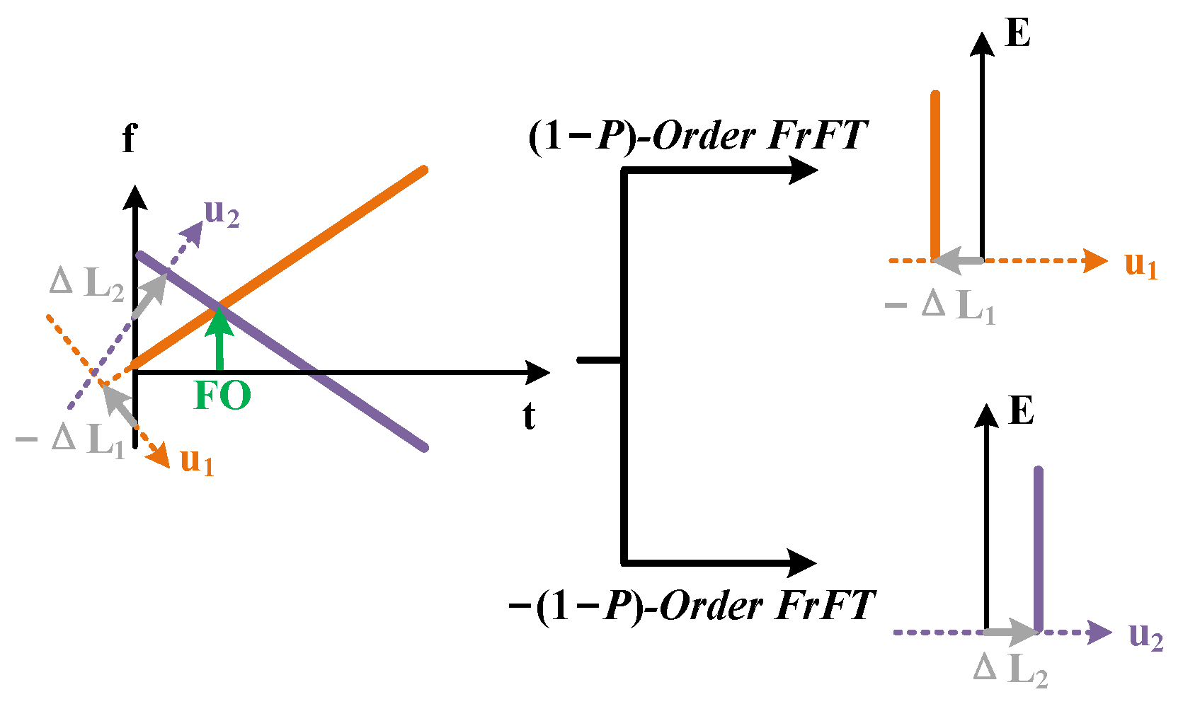
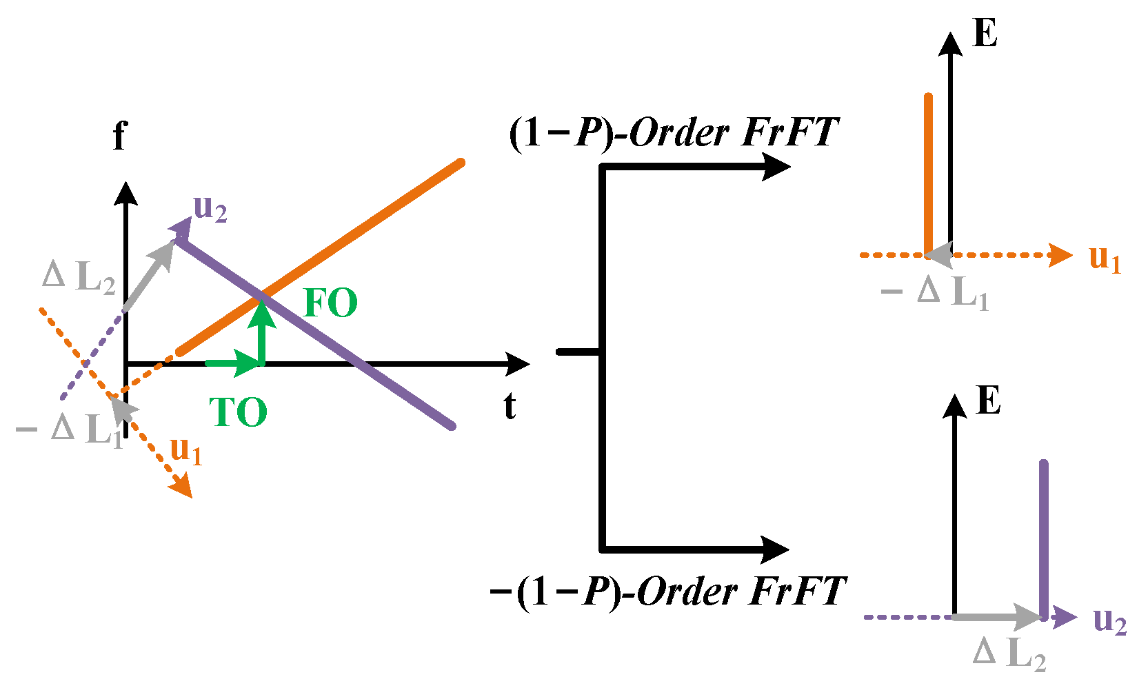
3.1. Frequency Offset Estimation Based on FrFT-DC Pilot

The FOE based on the FrFT-DC pilot is shown in Figure 6. When there is an FO between the transmitter and receiver lasers, the FrFT-DC pilot will shift along the frequency axis, with the shift corresponding to the FO. At the receiver side, the FrFT-DC pilot is firstly down-converted to base-band, and then a low-pass filter is used to extract the FrFT-DC pilot. The FrFT-DC pilot is processed with Q 1 -th ( Q 1 = 1 P 1 -order and Q 2 -th ( Q 2 = ( 1 P 1 ) )-order FrFTs, resulting in pulse peaks whose horizontal axis coordinates correspond to Δ L 1 and Δ L 2 , respectively. Considering the geometric relationship, the FO is determined using the two coordinates, as shown in Equation (11) [25,26]:
F O ^ = Δ L 2 Δ L 1 2 cos ( P 1 π 2 ) B L .
Here, B represents the baud rate of the FrFT-DC pilot, and L represents the number of symbols in the FrFT-DC pilot.

3.2. Clock Recovery Based on FrFT-DC Pilot

Figure 7 illustrates the timing offset estimation using the FrFT-DC pilot. A timing offset at the receiver causes the FrFT-DC pilot to shift along the time axis, with the shift directly corresponding to the timing offset. Following the FOE based on the FrFT-DC pilot, the signal undergoes down-conversion and low-pass filtering at the receiver side to isolate the pilot. Following extraction, the pilot undergoes Q 1 -th-order and Q 2 -th-order FrFT processing separately. Post-processing, pulse peaks appear at horizontal axis coordinates Δ L 1 and Δ L 2 . Leveraging the geometric relationship, the timing offset is determined using Equation (12) [25,26]:
T O ^ = Δ L 2 + Δ L 1 2 sin ( P 1 π 2 ) .
When both FO and timing offset are present, the FrFT-DC pilot shifts along both the time and frequency axes simultaneously. These two offsets are decoupled and correspond separately to the timing offset and FO. Therefore, FrFT-DC pilot can be used for joint FOE and timing recovery, as shown in Figure 8. The estimated FO and timing offsets are still given by Equations (11) and (12), respectively [25,26].

3.3. Vibration Sensing Based on FrFT-DC Pilot

Integrated vibration sensing and communication based on the FrFT-DC pilot is shown in Figure 9 and the experimental parameters are shown in Table 1. To optimize the performance of the FrFT-DC pilot for vibration sensing, a translation of the original FrFT-DC pilot is required to shift its central frequency, as Equation shown in (13) [32]:
P i l o t F r F T ( t ) = F P 1 ( D C ( t ) ) e j π B t + F P 1 ( D C ( t ) ) e j π B t .
Here, B represents the bandwidth of an FrFT-DC signal. The frequency shift yields a constant position shift of the peaks Δ L 0 in the fractional domain. However, since Δ L 0 is known, it is still possible to use the FrFT-DC pilot for both FOE and timing recovery [32].
For sensing purposes, vibrations induced by the piezoelectric transducer (PZT) in the link can cause Rayleigh back-scattering. By monitoring the Rayleigh back-scattering signal, a distributed vibration sensing system can be implemented using the FrFT-DC pilot. In the fiber link, a circulator is used to lead the Rayleigh back-scattering signal into the sensing receiver. The Rayleigh back-scattering signal is finally received by an ICR. The signal is then captured by an RTO with a low sampling rate. The FrFT-DC pilot is extracted by setting the analog bandwidth of the RTO. Finally, by processing the extracted FrFT-DC pilot with the matched filter [31], distributed vibration sensing is achieved. In experiment, distributed vibration sensing results demonstrate that the spatial resolution can achieve 5 m and the strain resolution can be 70 p ϵ / Hz [32].

4. Integrated Sensing and Communication Based on FPTs

In comparison with the integrated vibration sensing and communication scheme based on FrFT-DC pilots for back-scattering-based sensing, the FPT-based integrated scheme is more suitable for forward transmission vibration sensing. FPT is expressed as in Equation (14):
P i l o t F P T ( t ) = A e j 2 π f t .
Here, A represents the amplitude of the FPT, and the f represents the frequency of the FPT. By inserting specially designed FPTs into the carrier intervals of the DSCM system, FOE, CPE, and polarization demultiplexing can be achieved. Furthermore, SOP-based and phase-based vibration sensing can be achieved.
The signal spectra at the transmitter side are shown in Figure 10a. In the X polarization direction at frequency f 1 , an FPT is inserted, and in the Y polarization direction at frequency f 2 , an FPT is also inserted. Due to the symmetry of the center frequencies of subcarriers in the frequency domain, it follows that f 1 = f 2 .
After transmission through the fiber link, due to the rotation of SOP, the FPTs will cross-talk with each other. An FPT will appear at f 2 in the X polarization and another FPT will appear at f 1 the Y polarization. As a result, there are four FPTs in total [34]. Additionally, frequency offset, laser phase noise, and vibration-induced phase will cause the FPTs to shift and broaden [34]. The signal spectra at the receiver side are shown in Figure 10b.
On the receiver side, the four FPTs are firstly down-converted to base-band, and then low-pass filters are used to extract the four FPTs. The FPTs are expressed as follows [34]:
F 1 X F 2 X F 1 Y F 2 Y R x = e j ( ϕ P N + ϕ v i b + 2 π 0 t F O ( τ ) d τ ) × cos θ sin θ e j ϵ sin θ e j ϵ cos θ × A 0 0 A .
Here, F 1 X and F 1 Y represent the FPTs at f 1 in the X and Y polarizations, respectively; F 2 X and F 2 Y represent the FPTs at f 2 in the X and Y polarizations, respectively. A represents the amplitude of the FPTs at the transmitter side. ϕ P N and ϕ v i b represent the phase induced by laser phase noise and external vibration, respectively, F O ( τ ) represents the time-varying FO, and θ and ϵ represent the angle and phase parameters of SOP rotation. To achieve vibration sensing, the key task is to extract ϕ v i b from the total phase consisting of multiple terms.

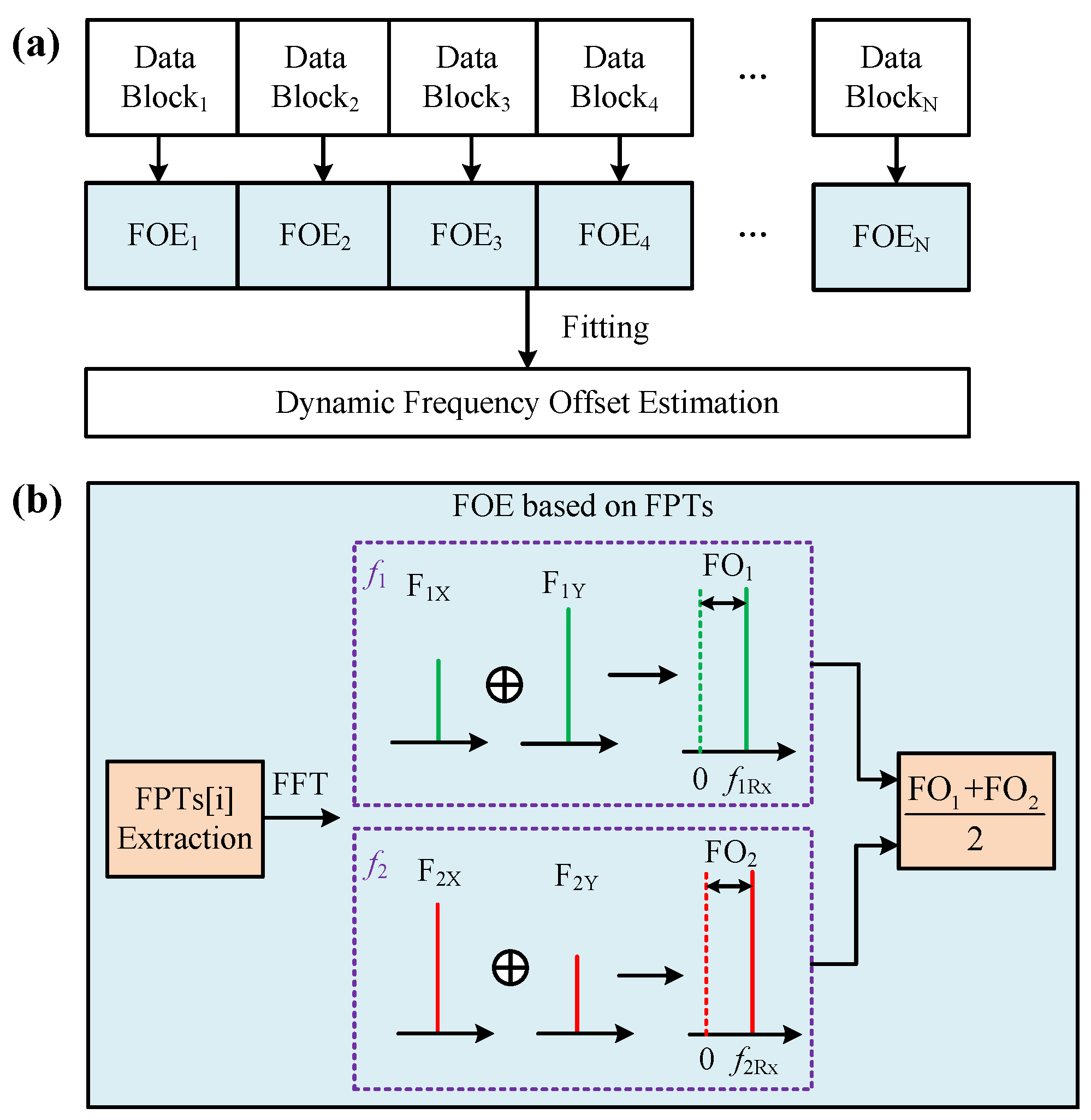
4.1. Frequency Offset Estimation Based on FPTs

In commercial coherent optical communication systems, the lasers typically are ECLs with a 3 dB linewidth of 100 kHz. The frequencies of ECLs drift over time, causing variation in the frequency offset. Dynamic FOE is necessary to compensate for the 0 t F O ( τ ) d τ .
The FPT-based dynamic FOE process is illustrated in Figure 11a. After extracting the FPTs, data blocks are formed on the FPTs, followed by FPT-based FOE for each block. The FPT-based FOE process is shown in Figure 11b. The fast Fourier transform (FFT) is firstly performed on the extracted FPTs and then spectra of both polarizations are combined at f 1 and f 2 , respectively, to mitigate the effects of polarization fading. The frequency offsets at f 1 and f 2 are determined by calculating the peak frequency shifts in their respective spectra, and the average of these two frequency offsets is taken as the frequency offset for this data block. The vibration-induced phase and laser-induced frequency offset phases additively affect the overall phase, resulting in additional estimated frequency offset fluctuations. In theory, the phase variations caused by vibrations result in a rapidly changing frequency offset component, whereas laser-induced frequency offset drift changes more slowly. Hence, polynomial fitting is utilized to mitigate the estimated frequency offset fluctuations induced by vibrations [34].

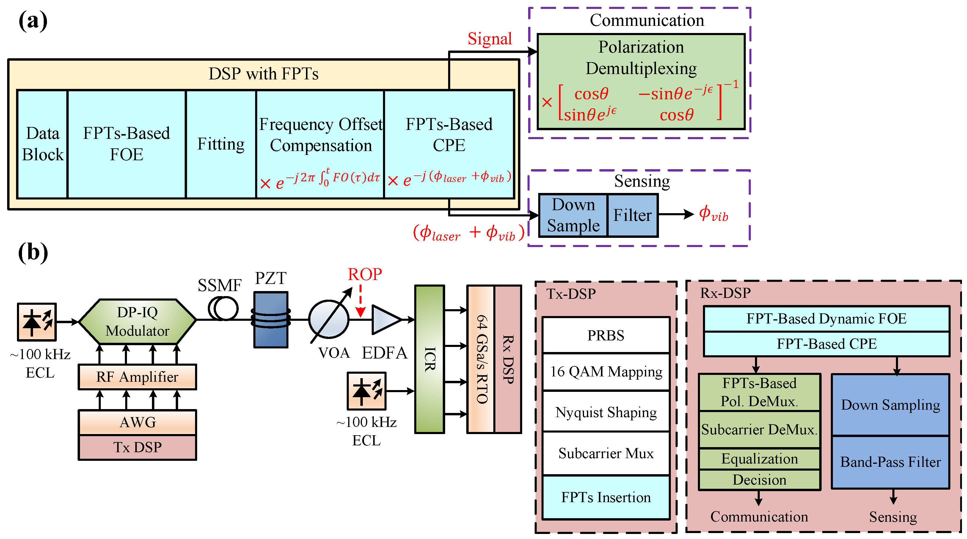
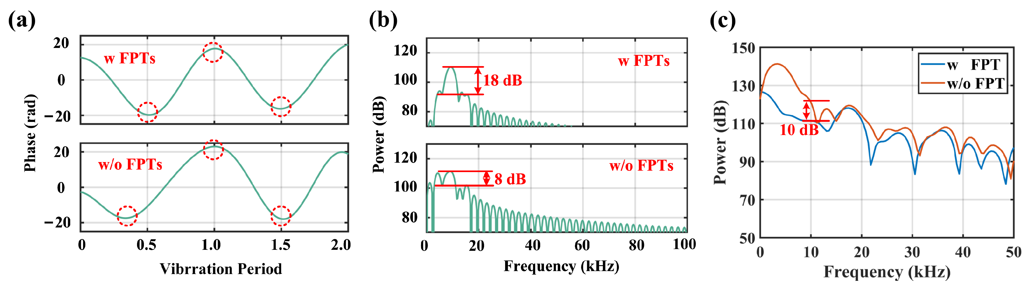
4.2. Carrier Phase Estimation Based on FPTs

After the dynamic frequency offset is compensated for, the four FPTs are expressed as Equation (16) [34]:
F 1 X F 2 X F 1 Y F 2 Y F O E = e j ( ϕ P N + ϕ v i b ) × cos θ sin θ e j ϵ sin θ e j ϵ cos θ × A 0 0 A .
Considering the characteristics of the Jones matrix, the carrier phase can be combined as shown in Equation (17) to avoid polarization fading [34]:
ϕ ^ C P E = arg ( F 1 X F 2 Y F 2 X F 1 Y ) 2 = arg ( A 2 e 2 j ( ϕ P N + ϕ v i b ) ) 2 = ( ϕ P N + ϕ v i b ) .
By following the above steps, a highly simplified CPE based on FPTs can be achieved. In comparison with CPE schemes based on blind phase search, CPE based on FPTs has extremely low algorithmic complexity.

4.3. State of Polarization Tracking Based on FPTs

After the frequency offset and the carrier phase are compensated, the FPTs are only affected by the SOP rotation. The FPTs are expressed as Equation (18) [34]:
F 1 X F 2 X F 1 Y F 2 Y C P E = cos θ sin θ e j ϵ sin θ e j ϵ cos θ × A 0 0 A .
To estimate the Jones matrix, the four FPTs are used together to compute the normalization factor, as shown below:
A ^ = F 1 X F 2 Y F 2 X F 1 Y = A 2 ( cos 2 θ + sin 2 θ ) = A .
Subsequently, Equations (18) and (19) are combined to calculate the Jones matrix as Equation (20):
M ^ = F 1 X F 2 X F 1 Y F 2 Y C P E A ^ = cos θ sin θ e j ϵ sin θ e j ϵ cos θ .
Because the conventional SOP tracking method based on MIMO filters requires multiple iterations, it has limitations for high-speed SOP tracking. In contrast, the FPT-based SOP tracking method does not require iterations and can effectively track higher-speed SOP variations [27].
Through the above steps, carrier recovery and polarization demultiplexing based on FPTs can be achieved. Compared to the conventional schemes, the FPT-based solution has the advantages of lower complexity and higher robustness. This is thanks in part to the high-precision carrier recovery and high-speed SOP tracking based on FPT. Due to the above advantages, FPTs can effectively improve the vibration sensing capability based on phase [34,35] and SOP [36].

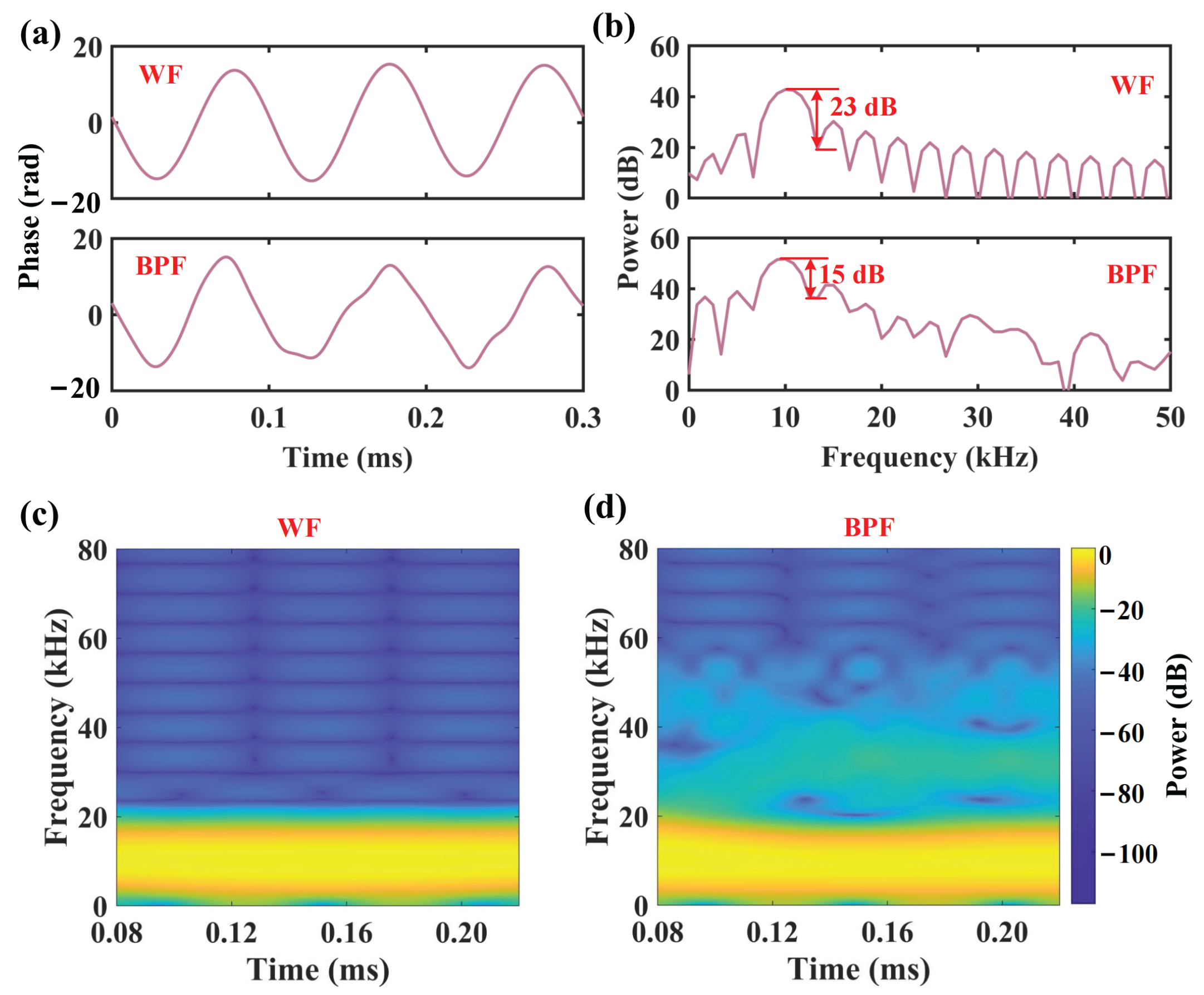
4.4. Phase-Based Vibration Sensing Using FPTs

An integrated communication and phase-based vibration sensing scheme is shown in Figure 12a. Firstly, dynamic FOE and CPE based on FPTs are performed on the received signal. For telecommunication signals, the FPTs are utilized for depolarization demultiplexing. Regarding the carrier phase, considering that vibration frequencies are generally below MHz, the phase is firstly down-sampled to the MHz level to reduce computational complexity. Subsequently, filters such as band-pass filters are applied to extract the vibration-induced phase [34].
In comparison to traditional dynamic FOE methods based on communication data, the FPT-based dynamic FOE effectively mitigates the influence of modulation formats on FOE and achieves higher accuracy. The accurate dynamic FOE based on FPTs suppresses background noise caused by residual frequency offset accumulation, thereby enhancing the sensing signal-to-noise ratio. Additionally, the FPTs-based scheme demonstrates superior robustness against inter-symbol interference compared to carrier recovery methods based on the communication data [34].
The experimental setup for demonstrating the integrated phase-based sensing and communication scheme is shown in Figure 12b and the experimental parameters are shown in Table 2. At the transmitter side, the pseudo-random binary sequence is mapped using dual-polarization 16-QAM symbols. Subsequently, the Nyquist shaping is performed on the signal using a root-raised-cosine (RRC) filter with a roll-off factor of 0.1. Then, the signal is subjected DSCM and up-sampled to the AWG sampling rate. Finally, the FPT at 10 GHz is inserted into X polarization and the FPT at −10 GHz is inserted into Y polarization. The center frequencies of the four subcarriers are set to −15 GHz, −5 GHz, 5 GHz, and 15 GHz, respectively, and the subcarrier intervals are set to 2 GHz. The symbol rate is set to 4 × 8 GBaud/s. An ECL with a 3 dB linewidth of 100 kHz is modulated by a dual-polarization in-phase and quadrature (DP-IQ) modulator driven by the AWG. After transmission through the SSMF, a variable optical attenuator (VOA) is used to adjust the received optical power (ROP) and an EDFA is used to compensate the loss of the fiber. At the receiver side, the signal and another ECL are coherently received by an ICR and the detected signals are captured by an RTO with a sampling rate of 64 GSa/s. Then, the received signals are processed by the ISAC scheme. For vibration sensing, vibration induced by a PZT is applied to the link.
In the aforementioned experimental system, forward-phase-based vibration sensing using FPTs is employed. As a comparison, the scheme described in [19] is used to process the subcarrier with a central frequency of −15 GHz. A 10 kHz sine vibration is applied to the link, and the vibration-induced phases are extracted using the same band-pass filter (BPF) with a passband from 5 kHz to 15 kHz. The extracted vibration-induced phases are shown in Figure 13a. The spectra of the vibration-induced phases are presented in Figure 13b, demonstrating that the FPTs-based scheme achieves a 10 dB sensing signal-to-noise improvement. Background noise is tested with both schemes without applying vibration and without BPF, as shown in Figure 13c. Compared to the forward-phase-based sensing using the communication data, forward-phase-based sensing using the FPTs achieves 10 dB sensing background noise suppression at 10 kHz [34].
Due to the phase noise of the laser causing background noise during sensing, the use of a band-pass filter for vibration-induced phase extraction is limited by the sensing signal-to-noise ratio. A WF can achieve adaptive and high-fidelity vibration-induced phase extraction [35]. Considering that the phase noise of the laser with a linewidth of Δ ν can be modeled as a Wiener process, its difference follows a Gaussian distribution as shown in Equation (3) [43]. The phase estimated by CPE is the sum of the laser phase noise and the vibration-induced phase and the WF is used to extract the vibration-induced phase from the sum item. Firstly, the estimated phase is differentiated to obtain Δ ϕ ^ :
Δ ϕ ^ = [ n ] = ϕ ^ C P E [ n ] ϕ ^ C P E [ n 1 ] = Δ ϕ P N [ n ] + Δ ϕ V i b [ n ] .
Subsequently, the autocorrelation matrix R Δ ϕ Δ ϕ of Δ ϕ is derived using Δ ϕ ^ as demonstrated in Equation (22):
R ^ Δ ϕ Δ ϕ = E ( Δ ϕ ^ Δ ϕ ^ H ) .
Under theoretical considerations, Gaussian noise is uncorrelated with the differential vibration signal, and the autocorrelation matrices of Δ ϕ v i b and Δ ϕ constitute Hermitian matrices. Consequently, Equations (23)–(25) are provided:
R Δ ϕ Δ ϕ = R Δ ϕ v i b Δ ϕ v i b + σ P N 2 I .
R Δ ϕ v i b Δ ϕ v i b = m = 1 M v m λ m v m H .
R Δ ϕ Δ ϕ = m = 1 M v m ( λ m + σ P N 2 ) v m H + m = M + 1 N v m σ P N 2 v m H .
Here, I represents the identity matrix. λ m represents the eigenvalue of the autocorrelation matrix of the differential vibration-induced phase ( R Δ ϕ v i b Δ ϕ v i b ), and v m is the corresponding eigenvector.
Under experimental considerations, the eigenvalues λ ^ m Δ ϕ and corresponding eigenvectors v ^ m of R Δ ϕ Δ ϕ can be derived by performing unitary decomposition on R ^ Δ ϕ Δ ϕ . By setting a threshold for the eigenvalues λ ^ m Δ ϕ to remove the eigenvalues of the laser phase noise, the eigenvalues and eigenvectors greater than the threshold are retained. The eigenvalues of R Δ ϕ v i b Δ ϕ v i b can be derived using Equation (26):
λ ^ m = λ ^ m Δ ϕ σ ^ P N 2 .
σ ^ P N 2 is the variance of the differential phase estimated by CPE when there is no vibration. Using maximum a posteriori (MAP) estimation, the differential vibration-induced phase can be obtained as shown in Equation (28) [35]:
Δ ϕ ^ v i b = arg min Δ ϕ v i b [ 1 σ P N 2 | | Δ ϕ v i b Δ ϕ | | 2 2 + | | R Δ ϕ Δ ϕ 1 Δ ϕ v i b | | 2 2 ] .
Δ ϕ ^ v i b = 1 σ ^ P N 2 ( 1 σ ^ P N 2 I + ( R ^ Δ ϕ v i b Δ ϕ v i b 1 ) T R ^ Δ ϕ v i b Δ ϕ v i b 1 ) 1 Δ ϕ ^ = m = 1 M v ^ m λ ^ m 2 λ ^ m 2 + σ ^ P N 2 v ^ m H Δ ϕ ^ .
Ultimately, through summation of Δ ϕ ^ v i b , the vibration-induced phase can be determined, as illustrated in Equation (29):
ϕ ^ v i b [ n ] = ϕ C P E [ 0 ] + m = 1 n Δ ϕ ^ v i b [ m ] .
By following the aforementioned procedure, WF-based vibration-induced phase extraction is achieved. Unlike traditional BPF-based methods, this approach eliminates the need for vibration frequency information and demonstrates higher adaptability. Under 10 kHz sinusoidal vibration conditions, the vibration-induced phase was extracted using both WF and a BPF with a passband from 5 kHz to 50 kHz. The results are shown in Figure 14a. The corresponding frequency spectra and short-time Fourier transform (STFT) spectra of the extracted phases are displayed in Figure 14b–d. It can be observed that the scheme based on WF achieved an 8 dB improvement in sensing signal-to-noise ratio, and the phase extraction based on WF exhibits more stable vibration frequency sensing and reduced sensing background noise power in the STFT spectra [35].

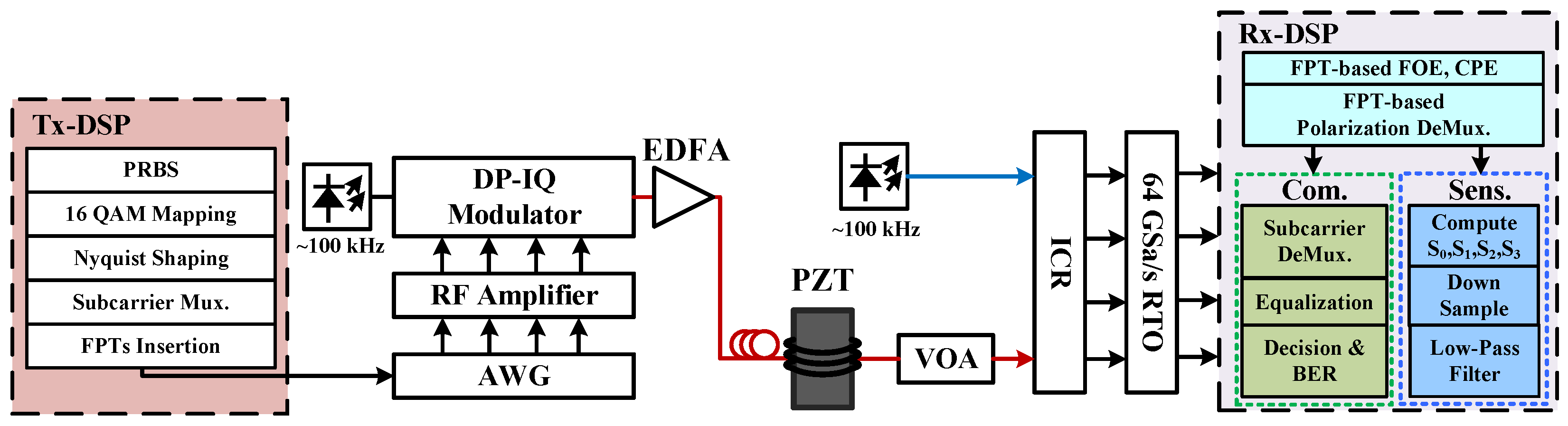
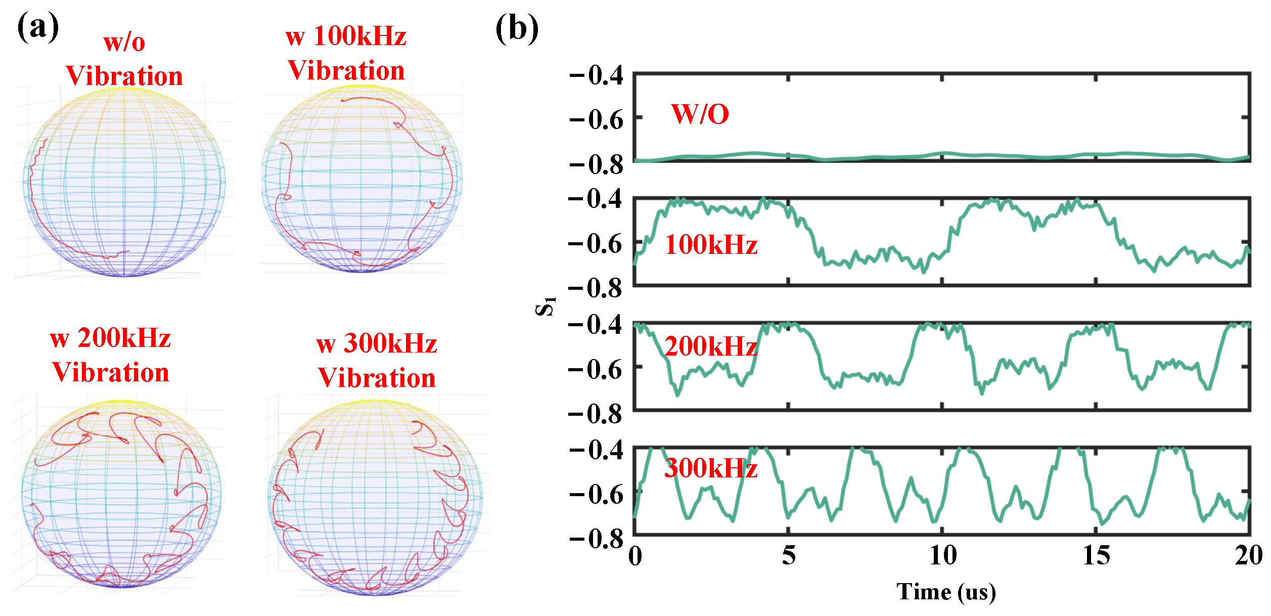
4.5. SOP-Based Vibration Sensing Using FPTs

External disturbances cause the fiber to undergo strain, which disrupts the fiber’s symmetry and results in changes in the SOP of the signals within the fiber. By monitoring the variations in the Stokes parameters caused by these SOP changes, one can achieve vibration sensing based on SOP. Since the FPT-based SOP tracking scheme does not require iterative MIMO filters, it enables high-speed tracking of SOP changes, making the Jones matrix calculated using FPTs suitable for implementing vibration sensing based on SOP.
The Jones matrix calculated using FPTs contains four parameters as follows:
M ^ = cos θ sin θ e j ϵ sin θ e j ϵ cos θ = J ^ x x J ^ x y J ^ y x J ^ y y .
Using the estimated Jones matrix, the Stokes parameters can be calculated, shown as follows [12]:
S 0 = | J ^ x x | 2 + | J ^ x y | 2 .
S 1 = [ | J ^ x x | 2 | J ^ x y | 2 ] / S 0 .
S 2 = 2 ( J ^ x y J ^ x x ) / S 0 .
S 3 = 2 ( J ^ x y J ^ x x ) / S 0 .
Here, ( · ) and ( · ) separately represent the real and imaginary parts of the data. The variation speed of the Stokes parameters can be obtained from the four parameters, as shown in Equation (35) [12,21]:
Δ S O P Δ t = 2 Δ t sin 1 ( 1 2 i = 1 3 ( Δ S i ) 2 ) .
Here, Δ t represents the sampling period between two measurements of SOP and Δ S i represents the associate Stokes parameter differences.
The experimental setup for the proposed integrated scheme is shown in Figure 15. The basic experimental setup and parameters are consistent with Figure 12. Here, the sensing information is derived from the Jones matrix calculated by FPTs. The Q-factors under different rotated SOP (RSOP) velocities using both FPTs and MIMO for polarization demultiplexing are tested, as shown in Figure 16. It can be seen that the polarization demultiplexing based on FPTs can achieve SOP tracking up to 100 Mrad/s. For events such as lightning, the SOP rotation speed can reach up to 30 Mrad/s [45], and FPTs can still track the SOP under these conditions, while MIMO failed. The experimental sensing results are shown in Figure 17; the SOP sensing scheme based on FPTs can achieve vibration detection up to 300 kHz [36].

5. Conclusions and Future Trends

In conclusion, this paper reviews two integrated DSCM communication and vibration sensing schemes: one based on FrFT-DC pilots and the other based on FPTs. The scheme using FrFT-DC pilots enables FOE and timing recovery in communication while empowering back-scattering-based sensing, achieving a 30 dB sensing signal-to-noise ratio at 1 kHz [32]. On the other hand, the scheme based on FPTs achieves multi-dimensional impairment monitoring and compensation in communication. In terms of sensing, it significantly achieves a 10 dB sensing signal-to-noise ratio improvement at 10 kHz for forward-phase-based sensing [34] and also increases detectable SOP rotation velocity to 100 Mrad/s for forward-SOP-based sensing. These results demonstrate that the insertion of specially designed pilots in DSCM systems can not only enhance communication performance but also improve sensing capabilities, providing feasible solutions for future integration sensing and communication deployment in fiber.
We summarize the representative research advances pertaining to ISAC in fiber optics, as shown in Table 3. In vibration sensing based on back-scattering, higher spatial resolution can be achieved. However, such schemes rely on NLLs to suppress phase noise. Additionally, under long-haul communication conditions, transmitting back-scattering signals over long distances proves challenging, thereby restricting the achievable sensing range. Furthermore, vibration sensing schemes based on back-scattering require an additional sensing receiver, facing challenges in low-cost integration. In vibration sensing based on forward SOP, the approach is fully compatible with commercial ECLs, but is constrained in high-frequency sensing applications. Inserting FPTs into DSCM systems for SOP tracking effectively improves the detectable frequency. In forward phase-based sensing, similar to back-scattering schemes, most schemes also depend on NLLs to suppress phase noise. Currently, there are some schemes using dynamic FOE that can achieve forward phase-based vibration sensing under commercial ECLs, and FPTs can effectively enhance the sensing signal-to-noise ratio. However, challenges remain in low-frequency vibration sensing under commercial ECLs. Furthermore, for both forward sensing schemes, their localization accuracy still needs to be improved.
Despite the aforementioned challenges, with increasing research focus, long-distance back-scattering sensing schemes based on specially designed EDFA [10] and Raman amplification [47] have begun to attract attention. Further, multi-point vibration localization schemes [46,48] are emerging as well under forward-transmission sensing conditions. Furthermore, WF has demonstrated the capability of laser phase noise suppression [35]. In addition, self-homodyne technology can also play a significant role in suppressing sensing background noise under commercial laser conditions [49]. We believe that in the future, integrated sensing and communication in fiber optics will become an effective solution for intelligent optical network operations and maintenance.

Author Contributions

Conceptualization, B.Y. and J.T.; project administration and supervision, J.W. and Y.Y.; investigation, Y.H., C.C. and S.W.; writing—original draft preparation, B.Y.; writing—editing, B.Y., J.T. and L.F.; writing—review, S.G., Z.S., J.L. and W.H. All authors have read and agreed to the published version of the manuscript.

Funding

This research was funded by the National Key Research and Development Program of China (2024YFB29NL00100), the Shenzhen Municipal Science and Technology Innovation Council (JCYJ20240813104835048), and the Shenzhen Research Foundation (KJZD20240903100014019).

Institutional Review Board Statement

Not applicable.

Informed Consent Statement

Not applicable.

Data Availability Statement

Not applicable.

Conflicts of Interest

The authors declare no conflicts of interest.

References

  1. Liu, X. Enabling optical network technologies for 5G and beyond. J. Light. Technol. 2022, 40, 358–367. [Google Scholar] [CrossRef]
  2. Winzer, P.J.; Neilson, D.T.; Chraplyvy, A.R. Fiber-optic transmission and networking: The previous 20 and the next 20 years. Opt. Express 2018, 26, 24190–24239. [Google Scholar] [PubMed]
  3. Ip, E.; Ravet, F.; Martins, H.; Huang, M.F.; Okamoto, T.; Han, S.; Narisetty, C.; Fang, J.; Huang, Y.K.; Salemi, M.; et al. Using Global Existing Fiber Networks for Environmental Sensing. Proc. IEEE 2022, 110, 1853–1888. [Google Scholar]
  4. Ip, E.; Huang, Y.K.; Wellbrock, G.; Xia, T.; Huang, M.F.; Wang, T.; Aono, Y. Vibration detection and localization using modified digital coherent telecom transponders. J. Light. Technol. 2022, 40, 1472–1482. [Google Scholar]
  5. Wang, Z.; Yang, H.; Li, Y.; Yao, Q.; Yu, T.; Zhang, C.; Liu, W.; Lin, W.; Zhang, J.; Liu, Y.; et al. Co-Route Fiber Recognition and Status Diagnosis Based on Integrated Sensing and Communication in 6G Transport Networks. IEEE Internet Things J. 2024, 11, 29348–29359. [Google Scholar]
  6. Zhang, M.; Wei, W.; Li, W.; He, H.; Chen, Y.; Wu, H.; Zhao, C.; Zhao, Z.; Tang, M. Endogenous BOTDA in the self-homodyne coherent detection transmission system for communication-integrated datacenter temperature monitoring. Opt. Lett. 2023, 48, 4749–4752. [Google Scholar] [CrossRef]
  7. Di Luch, I.; Ferrario, M.; Boffi, P.; Rizzelli, G.; Wang, H.; Gaudino, R. Demonstration of structural vibration sensing in a deployed PON infrastructure. In Proceedings of the 45th European Conference on Optical Communication (ECOC 2019), Dublin, Ireland, 22–26 September 2019; IEEE: Piscataway, NJ, USA, 2019; pp. 1–3. [Google Scholar]
  8. He, H.; Jiang, L.; Pan, Y.; Yi, A.; Zou, X.; Pan, W.; Willner, A.E.; Fan, X.; He, Z.; Yan, L. Integrated sensing and communication in an optical fibre. Light. Sci. Appl. 2023, 12, 25. [Google Scholar]
  9. Wang, J.; Lu, L.; Wang, L.; Yan, Y.; Lau, A.P.T.; Lu, C. High-efficiency ISAC to enable sub-meter level vibration sensing for coherent fiber networks. In Proceedings of the Optical Fiber Communication Conference, San Diego, CA, USA, 24–28 March 2024; Optica Publishing Group: Washington, DC, USA, 2024; p. Tu2J-3. [Google Scholar]
  10. Mazur, M.; Fontaine, N.K.; Kelleher, M.; Kamalov, V.; Ryf, R.; Dallachiesa, L.; Chen, H.; Neilson, D.T.; Quinlan, F. Continuous Distributed Phase and Polarization Monitoring of Trans-Atlantic Submarine Fiber Optic Cable. In Proceedings of the 2024 Optical Fiber Communications Conference and Exhibition (OFC), San Diego, CA, USA, 24–28 March 2024; IEEE: Piscataway, NJ, USA, 2024; pp. 1–3. [Google Scholar]
  11. Pellegrini, S.; Minelli, L.; Andrenacci, L.; Rizzelli, G.; Pilori, D.; Bosco, G.; Della Chiesa, L.; Crognale, C.; Piciaccia, S.; Gaudino, R. Overview on the state of polarization sensing: Application scenarios and anomaly detection algorithms. J. Opt. Commun. Netw. 2025, 17, A196–A209. [Google Scholar] [CrossRef]
  12. Boitier, F.; Lemaire, V.; Pesic, J.; Chavarría, L.; Layec, P.; Bigo, S.; Dutisseuil, E. Proactive fiber damage detection in real-time coherent receiver. In Proceedings of the 2017 European Conference on Optical Communication (ECOC), Gothenburg, Sweden, 17–21 September 2017; IEEE: Piscataway, NJ, USA, 2017; pp. 1–3. [Google Scholar]
  13. Mecozzi, A.; Cantono, M.; Castellanos, J.C.; Kamalov, V.; Muller, R.; Zhan, Z. Polarization sensing using submarine optical cables. Optica 2021, 8, 788–795. [Google Scholar]
  14. Zhan, Z.; Cantono, M.; Kamalov, V.; Mecozzi, A.; Müller, R.; Yin, S.; Castellanos, J.C. Optical polarization–based seismic and water wave sensing on transoceanic cables. Science 2021, 371, 931–936. [Google Scholar] [CrossRef]
  15. Mazur, M.; Wallberg, D.; Dallachiesa, L.; Börjeson, E.; Ryf, R.; Bergroth, M.; Josefsson, B.; Fontaine, N.K.; Chen, H.; Neilson, D.T.; et al. Field trial of FPGA-based real-time sensing transceiver over 524 km of live aerial fiber. In Proceedings of the Optical Fiber Communication Conference, San Diego, CA, USA, 5–9 March 2023; Optica Publishing Group: Washington, DC, USA, 2023; p. Tu3G-4. [Google Scholar]
  16. Tang, J.; Li, X.; Cheng, C.; Hao, Y.; Yang, B.; Li, J.; He, Z.; Yang, Y.; Hu, W. Forward-transmission based distributed fiber sensing compatible with C+ L unidirectional communication systems. In Proceedings of the 2024 Optical Fiber Communications Conference and Exhibition (OFC), San Diego, CA, USA, 24–28 March 2024; IEEE: Piscataway, NJ, USA, 2024; pp. 1–3. [Google Scholar]
  17. Carver, C.J.; Zhou, X. Polarization sensing of network health and seismic activity over a live terrestrial fiber-optic cable. Commun. Eng. 2024, 3, 91. [Google Scholar]
  18. Yan, Y.; Lu, L.; Wu, X.; Wang, J.; He, Y.; Chen, D.; Lu, C.; Lau, A.P.T. Simultaneous communications and vibration sensing over a single 100-km deployed fiber link by fiber interferometry. In Proceedings of the 2023 Optical Fiber Communications Conference and Exhibition (OFC), San Diego, CA, USA, 5–9 March 2023; IEEE: Piscataway, NJ, USA, 2023; pp. 1–3. [Google Scholar]
  19. Zuo, W.; Zhou, H.; Qiao, Y.; Zhao, Y.; Ye, B. Investigation of Co-Cable Identification Based on Ultrasonic Sensing in Coherent Systems. IEEE Photonics Technol. Lett. 2023, 35, 1155–1158. [Google Scholar]
  20. Zhou, H.; Zuo, W.; Qiao, Y.; Zhao, Y.; Ye, B.; Bai, C.; Xu, H. Ultrasonic phase extraction method for co-cable identification in coherent optical transmission systems. Chin. Opt. Lett. 2024, 22, 100601. [Google Scholar]
  21. Hu, K.; Tong, F.; Lian, W.; Li, W. Model and experimental verification of SOP transient in OPGW based on direct strike lightning. Opt. Express 2023, 31, 39102–39120. [Google Scholar] [CrossRef]
  22. Welch, D.; Napoli, A.; Bäck, J.; Buggaveeti, S.; Castro, C.; Chase, A.; Chen, X.; Dominic, V.; Duthel, T.; Eriksson, T.A.; et al. Digital subcarrier multiplexing: Enabling software-configurable optical networks. J. Light. Technol. 2023, 41, 1175–1191. [Google Scholar] [CrossRef]
  23. Neves, M.S.; Lorences-Riesgo, A.; Martins, C.S.; Mumtaz, S.; Charlet, G.; Monteiro, P.P.; Guiomar, F.P. Carrier-Phase Recovery for Coherent Optical Systems: Algorithms, Challenges and Solutions. J. Light. Technol. 2024, 42, 1095–1108. [Google Scholar]
  24. Golani, O.; Pilori, D.; Guiomar, F.P.P.; Bosco, G.; Carena, A.; Shtaif, M. Correlated nonlinear phase-noise in multi-subcarrier systems: Modeling and mitigation. J. Light. Technol. 2019, 38, 1148–1156. [Google Scholar]
  25. Zhou, H.; Li, X.; Tang, M.; Wu, Q.; Chen, X.; Luo, M.; Fu, S.; Liu, D. Joint timing/frequency offset estimation and correction based on FrFT encoded training symbols for PDM CO-OFDM systems. Opt. Express 2016, 24, 28256–28269. [Google Scholar]
  26. Hu, Z.; Chen, Y.; Chen, J.; Li, W.; Zhang, M.; Zhao, C.; Wang, L.; Zhao, L.; Tang, M. In-Advance Joint Timing/Frequency Synchronization Using FrFT Pilot for Digital Subcarrier Multiplexing Systems. J. Light. Technol. 2024, 42, 208–218. [Google Scholar]
  27. Fan, L.; Yang, Y.; Cheng, C.; Gong, S.; Xiang, Q.; Zhang, Q.; Yao, Y. Hardware-Efficient, Ultra-Fast and Joint Polarization and Carrier Phase Tracking Scheme Based on Frequency Domain Pilot Tones for DSCM Systems. J. Light. Technol. 2023, 41, 1454–1463. [Google Scholar]
  28. Fan, L.; Yang, Y.; Gong, S.; Zhang, Q.; Yao, Y. Robust PDL Compensation and Monitoring Scheme Using Frequency Domain Pilot Tones for Coherent Digital Subcarrier Multiplexing System. J. Light. Technol. 2024, 42, 136–148. [Google Scholar]
  29. Fan, L.; Yang, Y.; Zhang, Q.; Gong, S.; Jia, Y.; Yao, Y. Robust, in-service, and joint monitoring of a dual-polarization transceiver IQ skew for a coherent DSCM system without channel impairment compensation. Opt. Lett. 2023, 49, 129–132. [Google Scholar]
  30. Hu, Z.; Zhao, C.; Chen, Y.; Zhang, M.; Chen, J.; Li, W.; Tang, M. Simultaneous distributed acoustic sensing and communication in digital subcarrier multiplexing systems. In Proceedings of the 49th European Conference on Optical Communications (ECOC 2023), Glasgow, UK, 1–5 October 2023; IET: London, UK, 2023; Volume 2023, pp. 720–723. [Google Scholar]
  31. Hu, Z.; Chen, Y.; Jiang, H.; Zhang, M.; Chen, J.; Li, W.; Zhao, L.; Zhao, C.; Tang, M. Enabling cost-effective high-performance vibration sensing in digital subcarrier multiplexing systems. Opt. Express 2023, 31, 32114–32125. [Google Scholar] [PubMed]
  32. Hu, Z.; Zhang, M.; Li, Y.; Chen, J.; Li, W.; Xiong, Y.; Zhao, L.; Zhao, C.; Tang, M. Enabling endogenous distributed acoustic sensing in a digital subcarrier coherent transmission system. Opt. Lett. 2024, 49, 3166–3169. [Google Scholar]
  33. Hu, Z.; Zhao, C.; Chen, Y.; Zhang, M.; Chen, J.; Li, W.; Zhao, L.; Tang, M. Enabling Endogenous DAS in P2MP Digital Subcarrier Coherent Transmission System with Enhanced Frequency Response. In Proceedings of the 2024 Optical Fiber Communications Conference and Exhibition (OFC), San Diego, CA, USA, 24–28 March 2024; IEEE: Piscataway, NJ, USA, 2024; pp. 1–3. [Google Scholar]
  34. Yang, B.; Tang, J.; Cheng, C.; Fan, L.; Yang, P.; Wang, S.; Zhao, T.; Liang, J.; Gao, S.; Wei, J.; et al. Integrated Communication and Enhanced Forward Phase-based Sensing Based on Frequency-Domain Pilot Tones in DSCM Systems Using 100 kHz ECLs. J. Light. Technol. 2025, 43, 2664–2671. [Google Scholar]
  35. Yang, B.; Tang, J.; Cheng, C.; Fan, L.; Gao, S.; Yao, Y.; Liang, J.; Wei, J.; Yang, Y. High-fidelity and adaptive forward-phase-based vibration sensing using a Wiener filter in DSCM systems under commercial ECLs. Opt. Lett. 2025, 50, 554–557. [Google Scholar]
  36. Yang, B.; Tang, J.; Zhuo, Q.; Hao, Y.; Fan, L.; Wang, S.; Gao, S.; Liang, J.; Hu, W.; Yao, Y.; et al. Robust SOP-Based Vibration Sensing Integrated in DSCM System Based on Frequency-Domain Pilot Tones. In Proceedings of the Frontiers in Optics, Denver, CO, USA, 23–26 September 2024; Optica Publishing Group: Washington, DC, USA, 2024; p. FD1-6. [Google Scholar]
  37. Zhu, B.; Westbrook, P.; Feder, K.; Shi, Z.; Lu, P.; Dyer, R.; Sun, X.; Li, J.; Peterson, D.; DiGiovanni, D.J. Distributed Acoustic Sensing Over Passive Optical Networks Using Enhanced Scatter Fiber. In Proceedings of the Optical Fiber Communication Conference (OFC), San Diego, CA, USA, 24–28 March 2024; Optica Publishing Group: Washington, DC, USA,, 2024; p. M1K.1. [Google Scholar]
  38. Guerrier, S.; Dorize, C.; Pavani, H.; Mardoyan, H.; Awwad, É.; Renaudier, J. Digital Coherent Sensing over Deployed Fibers for Advanced Network Telemetry. In Proceedings of the Optical Fiber Communication Conference (OFC), San Diego, CA, USA, 24–28 March 2024; Optica Publishing Group: Washington, DC, USA, 2024; p. Tu2J.1. [Google Scholar]
  39. Liu, M.; Wang, J.; Chen, L.; Yu, C.; Lu, C. Integration of communication and distributed sensing over optical supervisory channel using live QPSK streams. Opt. Lett. 2025, 50, 1409–1412. [Google Scholar]
  40. Minelli, L.; Pellegrini, S.; Andrenacci, L.; Pilori, D.; Bosco, G.; Chiesa, L.D.; Tanzi, A.; Crognale, C.; Gaudino, R. SOP-based DSP blind anomaly detection for sensing on deployed metropolitan fibers. In Proceedings of the 49th European Conference on Optical Communications (ECOC 2023), Glasgow, UK, 1–5 October 2023; IET: London, UK, 2023; Volume 2023, pp. 519–522. [Google Scholar]
  41. Tomasov, A.; Dejdar, P.; Munster, P.; Horvath, T. Utilizing a State of Polarization Change Detector and Machine Learning for Enhanced Security in Fiber-Optic Networks. In Proceedings of the CLEO 2024, Charlotte, NC, USA, 5–10 May 2024; Optica Publishing Group: Washington, DC, USA, 2024; p. JTu2A.217. [Google Scholar]
  42. Tomasov, A.; Dejdar, P.; Munster, P.; Horvath, T.; Barcik, P.; Ros, F.D. Enhancing fiber security using a simple state of polarization analyzer and machine learning. Opt. Laser Technol. 2023, 167, 109668. [Google Scholar]
  43. Du, X.; Wang, Q.; Kam, P.Y. Maximum Likelihood Estimation of Wiener Phase Noise Variance in Coherent Optical Systems. J. Light. Technol. 2024, 42, 3163–3173. [Google Scholar] [CrossRef]
  44. Cohen, L. Time-frequency distributions-a review. Proc. IEEE 1989, 77, 941–981. [Google Scholar]
  45. Lian, W.; Su, X.; Hu, K.; Li, W.; Wu, B.; Zhao, H.; Huang, Y.; Zhang, S.; Wang, D.; Tong, F.; et al. Theoretical and experimental study on optical polarization states in overhead optical cables under complex weather conditions such as real lightning. Laser Phys. 2024, 35, 015101. [Google Scholar] [CrossRef]
  46. Zhu, R.; Rao, X.; Dai, S.; Chen, M.; Liu, G.; Liu, H.; Xu, R.; Chen, S.; Chen, G.Y.; Wang, Y. Deep Integration of Fiber-Optic Communication and Sensing Systems Using Forward-Transmission Distributed Vibration Sensing and on–off Keying. Sensors 2024, 24, 5758. [Google Scholar] [CrossRef] [PubMed]
  47. Ip, E.; Huang, Y.K.; Huang, M.F.; Yaman, F.; Wellbrock, G.; Xia, T.; Wang, T.; Asahi, K.; Aono, Y. DAS over 1007-km hybrid link with 10-Tb/s DP-16QAM co-propagation using frequency-diverse chirped pulses. J. Light. Technol. 2022, 41, 1077–1086. [Google Scholar] [CrossRef]
  48. Pang, Z.; Wang, G.; Wang, F.; Dai, H.; Li, W.; Wang, B. Fiber-based distributed sensing laser interferometer enabled by mirror-image correlation method. Adv. Photonics Nexus 2024, 3, 066007. [Google Scholar] [CrossRef]
  49. Hao, Y.; Yue, B.; Xu, Y.; Xiang, Q.; Fan, L.; Li, J.; Yang, Y.; Hu, W.; Li, X. Delayed Self-Heterodyne Interferometry Enabling 4.8 Tb/s Coherent Transmission and Simultaneous Vibration Sensing with 100 kHz Linewidth ECLs. In Proceedings of the 2024 Asia Communications and Photonics Conference (ACP) and International Conference on Information Photonics and Optical Communications (IPOC), Beijing, China, 2–5 November 2024; IEEE: Piscataway, NJ, USA, 2024; pp. 1–4. [Google Scholar]
Figure 1. Integrated vibration sensing and communication in fiber. The red arrows present the direction of light propagation and the gray arrows represent the direction of signal propagation.
Photonics 12 00290 g001
Figure 2. Integrated back-scattering-based sensing and communication in single-carrier systems. (a) Integrated DAS into WDM communication systems. (b) The experimental setup of DAS.
Photonics 12 00290 g002
Figure 3. Integrated forward-SOP-based sensing and communication in single-carrier systems.
Photonics 12 00290 g003
Figure 4. Integrated forward-phase-based sensing and communication in single-carrier systems.
Photonics 12 00290 g004
Figure 5. (a) Generation and energy centralization property of FrFT-DC signal. (b) Generation of FrFT-DC pilot at Tx. (c) Frame structure of DSCM signal with FrFT-DC pilot at Tx [25,26].
Photonics 12 00290 g005
Figure 6. Principles of FOE based on FrFT-DC pilot [25].
Photonics 12 00290 g006
Figure 7. Principles of timing offset estimation based on FrFT-DC pilot [25].
Photonics 12 00290 g007
Figure 8. Principles of joint FOE and timing offset estimation based on FrFT-DC pilot [25].
Photonics 12 00290 g008
Figure 9. Integrated vibration sensing and communication based on FrFT-DC pilot in DSCM system. (a) Experimental setup. DSPs at (b) transmitter side and (c) receiver side [32].
Photonics 12 00290 g009
Figure 10. Signal spectra on (a) transmitter side and (b) receiver side.
Photonics 12 00290 g010
Figure 11. (a) Dynamic FOE based on FPTs and (b) FOE based on FPTs [34].
Photonics 12 00290 g011
Figure 12. (a) Principles and (b) experimental setup for the integrated phase-based sensing and communication based on FPTs [34].
Photonics 12 00290 g012
Figure 13. Extracted phase variations induced by 10 kHz vibration with two schemes: (a) in time domain; (b) in frequency domain. (c) Spectra of background noise without any filter [34].
Photonics 12 00290 g013
Figure 14. Comparison of BPF method and WF method for 10 kHz sinusoidal vibration detection. Extracted vibration-induced phases based on two methods in (a) time domain and (b) frequency domain. STFT spectra of phases extracted by (c) WF method and (d) BPF method [35].
Photonics 12 00290 g014
Figure 15. Experimental setup for integrated SOP-based sensing and communication based on FPTs [36].
Photonics 12 00290 g015
Figure 16. Q-factors under different RSOP velocities using both FPTs and MIMO for SOP tracking.
Photonics 12 00290 g016
Figure 17. (a) Variations of Stokes parameters on Poincare Sphere. (b) Variations in S 1 parameter [36].
Photonics 12 00290 g017
Table 1. Experimental parameters of integrated communication and sensing based on FrFT-DC pilots [32].
ParameterValues
FrFT order±0.01
FrFT-DC symbol rate12.8 GBaud/s
Length of FrFT-DC sequence2048 symbols
Laser linewidth100 Hz
AWG sampling rate32 GSa/s
RTO sampling rate80 GSa/s
Communication symbol rate2 × 12.8 GBaud/s
Matched filterRRC
Roll-off factor of matched filter0.075
Length of fiber link10 km
Length of fiber used to wrap PZT15 m
Table 2. Experimental parameters of integrated communication and sensing based on FPTs [34].
ParameterValues
Center frequencies of subcarriers±5 GHz, ±15 GHz
Bandwidth of subcarrier interval2 GHz
Laser linewidth100 kHz
AWG sampling rate128 GSa/s
RTO sampling rate64 GSa/s
Symbol rate4 × 8 GBaud/s
Matched filterRRC
Roll-off factor of matched filter0.1
Length of fiber link40 km
Center frequency of FPT at X polarization10 GHz
Center frequency of FPT at Y polarization−10 GHz
Length of fiber used to wrap PZT5 m
Table 3. Advances in integrated sensing and communication within optical fibers.
TypeLaser LinewidthSensing CapabilitySpatial ResolutionCommunication SignalRef.
Back-Scattering<100 HzSNR = 21.5 dB @ 1 kHz *4 mPAM-4[8]
Back-Scattering<100 HzSNR = 21 dB @ 800 Hz0.5 m16-QAM[9]
Back-Scattering<100 HzSNR = 30 dB @ 1 kHz5 mDSCM 16-QAM[31,32]
Forward SOP<100 kHz f v i b ≤ 100 kHz **-QPSK[12]
Forward SOP<100 kHz f v i b = 100 kHz22.04 mQPSK[16]
Forward SOP<100 kHz f v i b ≥ 300 kHz-DSCM 16-QAM[36]
Forward Phase<100 Hz10 Hz ≤ f v i b ≤ 2 kHz5 km16-QAM[4]
Forward Phase<100 Hz8.3 p ϵ / Hz @ 1 kHz10.1 mOOK[46]
Forward Phase<100 kHzSNR = 19 dB @ 30 kHz-QPSK[19]
Forward Phase<100 kHzSNR = 18 dB @ 10 kHz-DSCM 16-QAM[34]
Forward Phase<100 kHzSNR = 23 dB @ 10 kHz-DSCM 16-QAM[35]
* Here, SNR represents the sensing signal-to-noise ratio. ** Here, f v i b represents the frequencies of vibrations.
Disclaimer/Publisher’s Note: The statements, opinions and data contained in all publications are solely those of the individual author(s) and contributor(s) and not of MDPI and/or the editor(s). MDPI and/or the editor(s) disclaim responsibility for any injury to people or property resulting from any ideas, methods, instructions or products referred to in the content.

