Communication

Precisely Tunable 780 nm External Cavity Diode Laser

1
Xi’an Institute of Space Radio Technology, Xi’an 710100, China
2
Wuhan Accelink Technologies Co., Ltd., Wuhan 430074, China
3
Laboratory of Optoelectronics and Sensor (OES Lab), School of Science, Hubei University of Technology, Wuhan 430068, China
*
Authors to whom correspondence should be addressed.
Photonics 2025, 12(4), 293; https://doi.org/10.3390/photonics12040293
Submission received: 9 February 2025 / Revised: 25 February 2025 / Accepted: 18 March 2025 / Published: 21 March 2025

Abstract

:
State-of-the-art research on narrow-linewidth external cavity semiconductor lasers has provided limited discussion on the capability of continuous wavelength tuning. In this study, we present a 780 nm tunable external cavity diode laser (ECDL) with narrow linewidth. An angle-adjustable interference filter (IF) is employed as the mode-selection element, enabling a wide wavelength tuning range. Precise, mode-hop-free continuous tuning is achieved through a combination of current modulation and piezoelectric ceramic transducer (PZT) control, with a tuning accuracy of 1.65 pm/mA. Experimental optimization of the interference filter external cavity diode laser (IF-ECDL) operating conditions resulted in a narrow linewidth of 55 kHz and a high output power of 51 mW. Furthermore, by integrating current and PZT tuning, continuous wavelength tuning of the IF-ECDL output is demonstrated over a specified range.

1. Introduction

Laser diodes (LDs) are widely utilized across various fields due to their compact size, high electrooptical conversion efficiency, high power density, rapid modulation speed, and ability to support both single-mode and multi-mode outputs [1]. However, their large divergence angle (typically ranging from a few degrees to 20 degrees) leads to poor directionality, monochromaticity, and coherence. Additionally, their relatively broad linewidth limits their suitability for modern applications such as frequency-modulated continuous wave (FMCW) LiDAR and high-capacity coherent communication. In this context, external cavity diode lasers (ECDLs) are preferred for their stability, high electro-optical conversion efficiency, and cost-effectiveness. ECDLs can produce narrow-linewidth, wavelength-stable, and tunable laser output, meeting the stringent requirements of applications such as spatially coherent laser communication [2,3], space exploration [4], environmental gas detection [5], spectral analysis [6], and atomic clocks [7]. By incorporating passive devices to form external cavity feedback, external cavity semiconductor lasers can effectively narrow the linewidth.
The theoretical foundation for laser linewidth narrowing was first established by Schawlow and Townes [8]. Two decades later, Lang and Kobayashi [9] applied external cavity feedback technology to LDs, achieving narrow laser linewidths and enabling wavelength tuning by adjusting the external cavity length. Building on this foundation, researchers successfully reduced laser linewidth to 1.5 MHz by employing diffraction gratings in the external cavity structure [10]. After 1988, ECDLs using narrow-bandwidth interference filters (IFs) and partially reflective mirrors for external feedback were developed, significantly enhancing stability against external perturbations [11,12,13]. These systems achieved narrow linewidth outputs across various wavelengths, with linewidths typically ranging from 20 kHz to 100 kHz and output powers below 40 mW at 780 nm and 852 nm [14,15,16,17,18]. However, most prior studies focused solely on laser performance at specific wavelengths, without providing detailed insights into their tunable capabilities.
In this work, we present an IF-ECDL operating at 780 nm. By employing passive external cavity feedback with a partially reflective mirror, we achieve substantial linewidth reduction. The integration of current tuning and piezoelectric ceramic transducer (PZT) tuning enables precise laser frequency control and single-frequency output while facilitating continuous wavelength tuning over a defined range. These features make the IF-ECDL an ideal candidate for applications demanding narrow-linewidth, high-precision light sources, such as quantum sensing.

2. Theoretical Analysis

2.1. Linewidth Analysis of External Cavity Laser

The linewidth of a laser is predominantly influenced by phase noise, and it can be derived from the phase noise of the laser. Experimental investigations have revealed that the linewidth value v 0 of LDs exceeds the prediction made by the Schawlow-Townes formula. To account for this discrepancy, an additional linewidth enhancement factor α has been introduced, which allows for a more accurate expression of the natural linewidth of the laser, as given by [19]:
v = 1 + α 2 v g 2 h v g n s p α m 8 π P 0 ,
where the linewidth enhancement factor α is influenced by the material properties of the LD and the injection current, and typically ranges from 2 to 6; v g is the group velocity; n s p is the spontaneous emission factor, being approximately 2 for LDs; h v is the photon energy; g is the chip gain; and αm is the output loss. When the laser works in a steady state, g = α m + α i n , where α i n is the internal loss. For an LD with a cavity length of L d , having cavity facet reflectivity of R 1 and R 2 , the output loss can be expressed in terms of optical intensity as given by:
α m = 1 2 L d ln 1 R 1 R 2 ,
where R 1 and R 2 are reflectivity of front and back cavity facets. The laser output power, denoted as P 0 , can be expressed in terms of the injection current into the laser, as given by:
P 0 = α m h v I I t h g q e ,
where I is the injection current, I t h is the threshold current, and q e is the electron charge. Using Equations (1)–(3), the natural linewidth of the LD can be further derived as:
v = q e v g 2 g 2 n s p 1 + α 2 8 π I I t h .
It is evident that for a specific type of LD, parameters such as intrinsic cavity length, facet reflectivities, and injection current significantly influence the intrinsic linewidth. Increasing the injection current, which subsequently raises the output power, proves beneficial for reducing the linewidth.
ECDLs can effectively reduce linewidth through two primary mechanisms. First, incorporating an external cavity will increase the laser’s effective cavity length, resulting in a narrower linewidth. Second, the introduction of external cavity feedback can enhance stimulated emission, suppress spontaneous emission, and further reduce the linewidth of the output laser. Under phase-matching conditions, the linewidth of the ECDL can be given as [20]:
v 0 = v 1 + α 2 X 2 = v n d L d 2 1 + α 2 R 3 L e 2 R 2 1 R 2 2 ,
where X is the external cavity optical feedback factor, obtained from:
X = 1 R 2 R 2 R 3 τ e τ d ,
where L d and L e are the lengths of the internal and external cavities, respectively, while τ d and τ e is the round-trip times of photons within these cavities. From Equation (5), it is evident that the linewidth v 0 of an ECDL is related to both the reflectivity of mirror R 3 and the external cavity length L e . Consequently, increasing the reflectivity or extending the external cavity length effectively reduces the linewidth. Typically, the external cavity length in an ECDL is significantly greater than the intrinsic cavity length of the LD. Theoretically, this results in a linewidth reduction by several orders of magnitude.

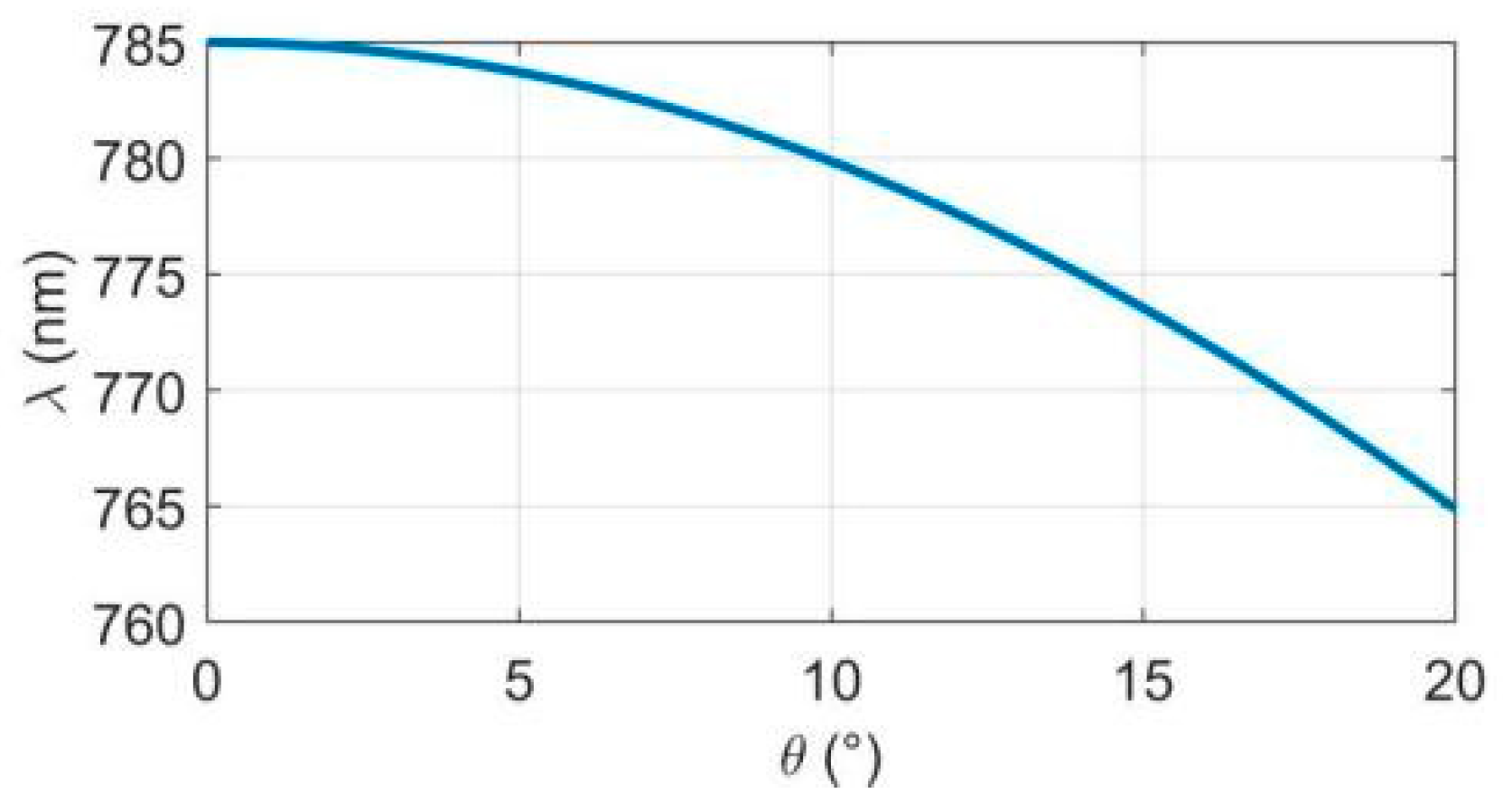
2.2. Frequency Selection Principle

For an ECDL, the longitudinal mode spacing is given by Equation (7) [21], where n d is the refractive index of the active region.
λ e = λ 2 2 L e + n d L d
As shown in Equation (7), the spacing of longitudinal modes is inversely proportional to the length of the external cavity. Since the external cavity length is significantly greater than the intrinsic cavity length, the spacing between the laser’s resonant modes decreases, reducing the frequency difference between adjacent modes. With proper cavity design and gain control, the laser can achieve tuning more easily by selectively amplifying a single mode. However, this also increases the demand for precise frequency selection.
In this study, an IF is used to select the frequency of the laser. When illuminated at a specific incidence angle θ , we can calculate the corresponding wavelength λ at the peak transmittance based on the theory of multi-beam interference [22]:
T = 1 1 + 4 R 1 R 2 sin 2 ( 2 π n I F d cos θ λ ) ,
where λ max is the center wavelength of the IF, and n I F is the refractive index of the IF. By utilizing an appropriately designed IF and combining it with mode competition, single-mode operation can be achieved. Figure 1 shows the variation of the transmission peak wavelength of an IF with a center wavelength of 780 nm. It can be observed that as the incidence angle increases, the transmitted wavelength shifts towards the shorter wavelength direction.

3. Structure and Performance Analysis of IF-ECDL

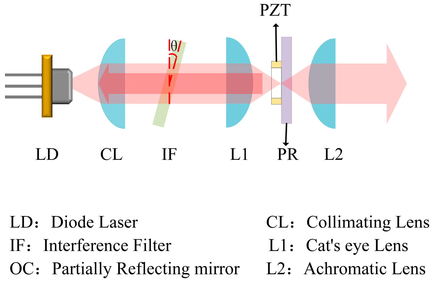
3.1. Structure of IF-ECDL

The schematic diagram of the IF-ECDL structure is shown in Figure 2. From left to right, the setup comprises a laser diode (LD), a collimating lens, an interference filter (IF), a cat’s eye lens, and a partially reflective mirror controlled by a piezoelectric ceramic transducer (PZT). The LD is mounted on a heat sink and its temperature is precisely regulated by a thermoelectric cooler (TEC). To suppress intracavity feedback, the front facet of the LD (depicted on the right side of the diagram) is coated with an anti-reflective film, while the rear facet is coated with a high-reflective film. The high-reflection surface of the LD, along with the partially reflective mirror, forms the two ends of the external cavity. The collimating lens, IF, and mirror collectively constitute the external cavity structure of the IF-ECDL, providing strong external feedback while minimizing the influence of the internal cavity’s longitudinal modes. Light emitted from the LD passes through the collimating lens and is filtered by the IF before reaching the partially reflective mirror, which is controlled by the PZT. This mirror reflects the light back into the active region of the LD, creating optical feedback. The PZT enables precise adjustments to the position of the partially reflective mirror, facilitating the selection of different modes. The selected mode resonates within the cavity, and when sufficient energy is accumulated, it generates the laser output. This design ensures narrow linewidth and tunable laser performance.
The interference filter has a nominal central wavelength of λ = 780 nm and a bandwidth of 3 nm, while the reflectance of the partial reflector is 0.3. CL is an aspheric lens with a focal length of f = 4.5 mm and a numerical aperture (NA) of 0.55. L1 is another aspheric lens with a focal length of f = 11 mm and a numerical aperture (NA) of 0.25. L2 is an achromatic lens with a focal length of f = 20 mm. By adjusting the optical mount, we fine-tune the direction of each component to achieve the optimal output of the laser. The adjusted optical assembly is then mounted on an aluminum plate to minimize acoustic vibrations. The interference filter (IF) is positioned at a tilt angle of 9.5°. After re-collimation, the output light is coupled into a polarization-maintaining fiber using a collimator, enabling precise testing of the laser’s performance.

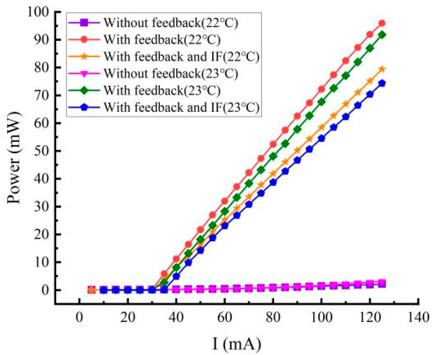
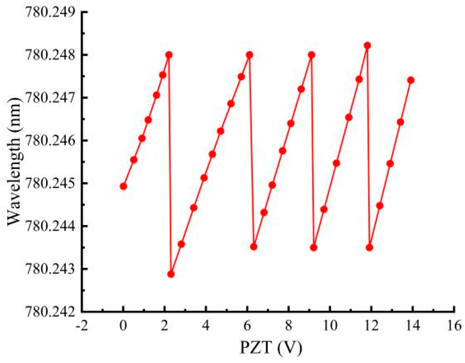
3.2. Performance Analysis

We monitor the power variation using the THORLABS PM320E optical power meter. At controlled temperatures of 22 °C and 23 °C, power-current (PI) curves were measured under three conditions: without external cavity feedback, with external cavity feedback, and with both external cavity feedback and an interference filter (IF), as shown in Figure 3. As the temperature increased, the threshold current exhibited a slight rise, attributed to the increased diffusion energy of injected carriers at higher temperatures, which reduces the gain. Without external cavity feedback, the laser diode’s (LD) front surface, coated with an anti-reflective film, effectively suppressed internal cavity feedback, resulting in negligible lasing. Upon introducing external cavity light feedback, stable laser oscillation was achieved, and the output power increased nearly linearly with the drive current. However, when the IF was added to the resonator alongside the external cavity feedback, the output power decreased compared to the case without the IF, due to the insertion loss associated with the filter. At 22 °C, under conditions of external cavity feedback and IF, the maximum output power reached 79 mW at a driving current of 125 mA.
The Yokogawa AQ6370D optical spectrum analyzer was used to detect wavelength variations. With the PZT voltage set to 0 V, the temperature maintained at 22 °C, and the LD driving current adjusted, the output wavelength of the IF-ECDL was measured, as shown in Figure 4. It was observed that the output wavelength varied with changes in the driving current, attributable to alterations in the thermal and optical parameters of the cavity region. This demonstrates that the driving current has a significant influence on the laser’s output wavelength, enabling tuning within a specific range. From the data, as the LD driving current increased from 49 mA to 95 mA, the output wavelength shifted from 780.212 nm to 780.288 nm, resulting in a tuning range of 76 pm (equivalent to 37 GHz). Due to the mode selection constraints imposed by the IF, wavelength jumps were observed at driving currents of 49 mA and 95 mA. Additionally, given the approximate laser cavity length of 6 cm, the longitudinal mode spacing was around 5.12 pm, producing steps of approximately 4.91 pm in the tuning output curve. The wavelength change rate induced by the driving current was determined to be 1.65 pm/mA.
With the PZT voltage set to 0 V and the temperature maintained at 23 °C, the output wavelength of the IF-ECDL was measured as a function of the LD driving current, as shown in Figure 5. The output wavelength exhibited a similar variation trend with the driving current as observed at a controlled temperature of 22 °C. However, due to the significant influence of temperature on the gain region’s characteristics, the continuous tuning range of the driving current spanned from 73 mA to 114 mA, encompassing a complete current tuning range. Furthermore, temperature also affected the resonator and IF characteristics, resulting in slight variations in the output wavelength range. These experimental results demonstrate that the laser’s tuning behavior is highly sensitive to temperature changes, underscoring the importance of precise thermal control in achieving stable and accurate wavelength tuning.
Based on the above experiments, it can be concluded that the IF-ECDL achieves precise tuning over a narrow range by accurately adjusting the drive current. The laser cavity length is approximately 6 cm, corresponding to a longitudinal mode spacing of about 5 pm. During current tuning, mode hops with a spacing of approximately 4.91 pm were observed. To overcome this, a PZT was employed to control the translation of the partially reflective mirror along the optical path, enabling fine adjustments to the cavity length and achieving continuous tuning output without mode hopping. The tuning characteristics are shown in Figure 6. The experimental results demonstrate that controlling the PZT voltage allows fine-tuning of the cavity length, facilitating continuous tuning of the laser output. With the IF-ECDL drive current set to 95 mA, varying the PZT voltage from 0 to 14 V produced several periodic tuning outputs. Within the voltage range of 2.31 V to 6.11 V, the laser output exhibited good linearity, achieving continuous scanning over a tuning range of approximately 5.12 pm (2.5 GHz). The wavelength variation rate was calculated to be 1.347 pm/V. The voltage control accuracy of the source meter used in the experiment was 0.001 mV, which theoretically corresponded to a laser mode selection accuracy of 0.00001 pm.
The linewidth of the IF-ECDL was measured using the beat frequency method, with the experimental setup illustrated in Figure 7. Light beams from two identical lasers interfered at the optical coupler, generating an interference signal due to the beat frequency. An optical attenuator was incorporated to prevent excessive light intensity from damaging the photodetector (PD). The PD converted the optical signal into an electrical signal, which was subsequently analyzed as the beat frequency signal using the RIGOL DSA 815-TG spectrum analyzer. Since both the reference laser and the tested laser were identical in design and performance, the linewidth of the tested laser was determined to be half of the 3 dB bandwidth of the beat frequency signal. This method provides a reliable and accurate measure of the laser’s linewidth.
With the driving current set to 95 mA and the operating temperature maintained at 23 °C, the IF-ECDL was operated at a wavelength of 780.246 nm. This represented the designated operating point for the laser. The linewidth, measured using the beat frequency method, is shown in Figure 8. The spectral line shape of the semiconductor laser closely resembled a Lorentzian profile, as did the photocurrent spectrum. The 3 dB bandwidth was determined to be twice the laser’s linewidth, resulting in a measured linewidth of 55 kHz at this operating point. Using a Lorentzian function for curve fitting, the linewidth was further refined and determined to be 61 kHz. These results confirm the narrow-linewidth performance of the IF-ECDL under the specified operating conditions.

4. Conclusions

This work presents the design of a compact and structurally simple IF-ECDL. By precisely adjusting the angle of the interference filter (IF), a wide range of wavelength tuning can be achieved. Fine-tuning over a narrower range is accomplished through adjustments to the driving current. When combined with PZT tuning, this approach effectively eliminates mode-hopping, enabling continuous, mode-hop-free tuning within a specific range. At the optimal operating point, the IF-ECDL delivers a laser output power of 51 mW at a wavelength of 780.246 nm, with a linewidth of approximately 55 kHz. This performance makes it a reliable laser source for rubidium (Rb) atomic clock applications. Future research could investigate its potential for broader applications in other precision instruments and scientific fields, further enhancing its utility in advanced technologies.

Author Contributions

Conceptualization, C.G. and B.H.; methodology, B.H.; software, Y.S.; validation, X.T., Y.S. and J.Y.; formal analysis, J.L.; investigation, J.Y.; resources, R.S.; data curation, J.L.; writing—original draft preparation, J.Y.; writing—review and editing, J.Y.; visualization, B.H.; supervision, C.G. and R.S.; project administration, Y.S.; funding acquisition, X.T. All authors have read and agreed to the published version of the manuscript.

Funding

Thanks to Hefei National Laboratory Quantum Science and Technology Instrument special project (Project Number: 2023YQ02001) for the strong support.

Institutional Review Board Statement

Not applicable.

Informed Consent Statement

Not applicable.

Data Availability Statement

Data are contained within the article.

Conflicts of Interest

Author Chenggang Guan and Rongxu Shen were employed by the company Wuhan Accelink Technologies Co., Ltd. The remaining authors declare that the research was conducted in the absence of any commercial or financial relationships that could be construed as a potential conflict of interest.

References

  1. Huber, G.; Kränkel, C.; Petermann, K. Solid-state lasers: Status and future. J. Opt. Soc. Am. B 2010, 27, B93–B105. [Google Scholar] [CrossRef]
  2. Mukhtar, S.; Xiaobin, S.; Ashry, I.; Ng, T.K.; Ooi, B.S.; Khan, M.Z.M. Tunable violet laser diode system for optical wireless communication. IEEE Photonics Technol. Lett. 2020, 32, 546–549. [Google Scholar] [CrossRef]
  3. Xia, F.; Chen, X.; Chen, A.; Liu, J.; Feng, X.; Zheng, S.; Liu, Z. Spaceborne Miniaturized Laser Communication Terminal’s Current Situation and Development Trend. Space Electron. Technol. 2020, 17, 73–80. [Google Scholar]
  4. Zhao, Y.M.; Fi, L.; Pan, C. Design of space-borne atmospheric detection lidar based on dual-wavelength polarization detection. Chin. Space Sci. Technol. 2023, 43, 150–159. [Google Scholar]
  5. Gasmi, K.; Aljalal, A.; Al-Basheer, W. Blue external-cavity diode laser for NO2 gas detection. In Proceedings of the Semiconductor Lasers and Laser Dynamics IX, Online, 6–10 April 2020; pp. 140–147. [Google Scholar]
  6. Yang, Q.-F.; Shen, B.; Wang, H.; Tran, M.; Zhang, Z.; Yang, K.Y.; Wu, L.; Bao, C.; Bowers, J.; Yariv, A.; et al. Vernier spectrometer using counterpropagating soliton microcombs. Science 2019, 363, 965–968. [Google Scholar] [CrossRef] [PubMed]
  7. Jiang, Y.Y.; Ludlow, A.D.; Lemke, N.D.; Fox, R.W.; Sherman, J.A.; Ma, L.-S.; Oates, C.W. Making optical atomic clocks more stable with 10- 16-level laser stabilization. Nat. Photonics 2011, 5, 158–161. [Google Scholar] [CrossRef]
  8. Schawlow, A.L.; Townes, C.H. Infrared and optical masers. Phys. Rev. B 1958, 112, 1940–1949. [Google Scholar] [CrossRef]
  9. Lang, R.; Kobayashi, K. External optical feedback effects on semiconductor injection laser properties. IEEE J. Quantum Electron. 1980, 16, 347–355. [Google Scholar] [CrossRef]
  10. Fleming, M.; Mooradian, A. Spectral characteristics of external-cavity controlled semiconductor lasers. IEEE J. Quantum Electron. 1981, 17, 44–59. [Google Scholar] [CrossRef]
  11. Zorabedian, P.; Trutna, W., Jr. Interference-filter-tuned, alignment-stabilized, semiconductor external-cavity laser. Opt. Lett. 1988, 13, 826–828. [Google Scholar] [CrossRef] [PubMed]
  12. Baillard, X.; Gauguet, A.; Bize, S.; Lemonde, P.; Laurent, P.; Clairon, A.; Rosenbusch, P. Interference-filter-stabilized external-cavity diode lasers. Opt. Commun. 2006, 266, 609–613. [Google Scholar] [CrossRef]
  13. Iwata, Y.; Cheon, D.; Miyabe, M.; Hasegawa, S. Development of an interference-filter-type external-cavity diode laser for resonance ionization spectroscopy of strontium. Rev. Sci. Instrum. 2019, 90, 123002. [Google Scholar] [CrossRef] [PubMed]
  14. Ruan, J.; Liu, J.; Ma, J.; Du, Z.; Wu, C.; Zhang, S. Robust external cavity diode laser system with high frequency stability for Cs atomic clock. Chin. Opt. Lett. 2010, 8, 300–302. [Google Scholar] [CrossRef]
  15. Thompson, D.J.; Scholten, R.E. Narrow linewidth tunable external cavity diode laser using wide bandwidth filter. Rev. Sci. Instrum. 2012, 83, 023107. [Google Scholar] [CrossRef] [PubMed]
  16. Pan, G.-Z.; Guan, B.-L.; Xu, C.; Li, P.-T.; Yang, J.-W.; Liu, Z.-Y. Broad bandwidth interference filter-stabilized external cavity diode laser with narrow linewidth below 100 kHz. Chin. Phys. B 2018, 27, 014204. [Google Scholar] [CrossRef]
  17. Wei, C.-h.; Zuo, C.-l.; Liang, L.; Yan, S.-h. Compact external cavity diode laser for quantum experiments. Optoelectron. Lett. 2020, 16, 433–436. [Google Scholar] [CrossRef]
  18. Wu, F.; Sun, H.; Wang, C.; Qi, Z. Development of a 780 nm narrow line width semiconductor laser device. In Proceedings of the Semiconductor Lasers and Applications IX, Hangzhou, China, 20–23 October 2019; pp. 58–63. [Google Scholar]
  19. Matthews, M.; Cameron, K.; Wyatt, R.; Devlin, W. Packaged frequency-stable tunable 20 kHz linewidth 1.5 μm InGaAsP external cavity laser. Electron. Lett. 1985, 21, 113–115. [Google Scholar] [CrossRef]
  20. Han, J.; Zhang, J.; Shan, X.; Zhang, Y.; Peng, H.; Qin, L.; Wang, L. High-power narrow-linewidth 780 nm diode laser based on external cavity feedback technology of volume Bragg grating. Optik 2022, 264, 169455. [Google Scholar] [CrossRef]
  21. Liu, J.-Y.; He, J.; Wang, J.-M. Optimization of 852nm Narrow-band Filter External Cavity Feedback Semiconductor Laser. J. Quantum Opt. 2018, 24, 98–106. [Google Scholar]
  22. Hu, S.; Lv, P.; Guan, C.; Li, S.; Qin, H.; Li, X.; Chen, X.; Zhan, L.; Wang, W.; Xiao, Y.; et al. Study on Linewidth and Phase Noise Characteristics of a Narrow Linewidth External Cavity Diode Laser. Sensors 2024, 24, 1103. [Google Scholar] [CrossRef] [PubMed]
Figure 1. The relationship between the transmitted wavelength of the IF and the incidence angle θ .
Photonics 12 00293 g001
Figure 2. Schematic diagram of IF-ECDL structure.
Photonics 12 00293 g002
Figure 3. PI curves at 22 °C and 23 °C for cases without feedback, with feedback without IF, and with feedback with IF.
Photonics 12 00293 g003
Figure 4. Driving current tuning curve (T = 22 °C).
Photonics 12 00293 g004
Figure 5. Driving current tuning curve (T = 23 °C).
Photonics 12 00293 g005
Figure 6. Modulation characteristics of PZT (T = 23 °C).
Photonics 12 00293 g006
Figure 7. Beat frequency method structure diagram for measuring linewidth.
Photonics 12 00293 g007
Figure 8. Results of linewidth testing using the beat frequency method.
Photonics 12 00293 g008
Disclaimer/Publisher’s Note: The statements, opinions and data contained in all publications are solely those of the individual author(s) and contributor(s) and not of MDPI and/or the editor(s). MDPI and/or the editor(s) disclaim responsibility for any injury to people or property resulting from any ideas, methods, instructions or products referred to in the content.

