Article

Adaptive Generation Method for Small Volume Easy Fabrication Freeform Unobscured Three-Mirror Systems Based on Machine Learning

1
School of Computer Science and Engineering, Northeastern University, Shenyang 110819, China
2
College of Mechanical Engineering and Automation, Northeastern University, Shenyang 110819, China
*
Author to whom correspondence should be addressed.
Photonics 2025, 12(5), 405; https://doi.org/10.3390/photonics12050405
Submission received: 20 January 2025 / Revised: 26 March 2025 / Accepted: 21 April 2025 / Published: 22 April 2025
(This article belongs to the Special Issue Emerging Topics in Freeform Optics)

Abstract

:
Freeform unobscured multiple-mirror systems have been widely applied in high-precision optical fields due to their high imaging quality and no chromatic aberration and central obstruction. However, how to design a freeform unobscured multiple-mirror system with small system volume, imaging quality, and low manufacturing difficulty is challenging. This study proposes an adaptive generation method for freeform unobscured three-mirror systems with small volume and ease of fabrication based on machine learning, considering the fabrication constraints, volume limitations, imaging quality, and design efficiency. First, an error function based on volume, fabrication, and imaging quality functions is constructed, and a dataset is generated using this error function. Then, a machine learning model is trained using this dataset, enabling efficient prediction of the parameters for small-volume, easy-to-fabricate freeform unobscured three-mirror systems. Finally, the parameters of the freeform unobscured three-mirror system are predicted using the trained model, and combined with the freeform surface generation method, a freeform unobscured three-mirror imaging system is automatically obtained. Experimental results demonstrate that our method can effectively generate freeform unobscured three-mirror systems that meet the requirements for small volume and easy fabrication, providing a new approach for optical design.

1. Introduction

Due to their unique structure, freeform unobscured multiple-mirror systems offer superior imaging quality, with no chromatic aberration or center obscuration. These systems are widely applied in high-precision optical fields, such as astronomical observation, heads-up display systems, and virtual reality systems [1,2,3,4,5].
Optical design techniques and manufacturing capabilities significantly impact the imaging performance of freeform unobscured multiple-mirror reflective systems. Therefore, designing a system that is both lightweight and low in manufacturing complexity, while ensuring imaging quality, has become an important research topic in optical design and engineering. The imaging quality is the primary focus of the current approaches to unobscured freeform reflective system design [6]. However, freeform unobscured multiple-mirror systems are typically integrated into specific devices, which means that large optical system’s volume results in an increase in the device’s weight and size, raising material consumption and costs while reducing convenience. In recent years, researchers have proposed methods for automatically compressing the volume of unobscured reflective systems. For instance, Liu et al. proposed a method to reduce the beam overlap area to automatically shrink the volume of unobscured freeform reflective systems [7]. Qu et al. designed a composite evaluation function that incorporates both aberration and volume calculations, and used this function to search for compact unobscured three-mirror reflective systems [8]. These methods enhance the optical system’s lightweight design while maintaining the image quality. However, before the unobscured reflective system is practically deployed, it usually needs to go through stages, such as design and fabrication [9]. Current compact design methods are typically based on a serial design process and do not concurrently consider the fabrication complexity of the optical system during the design phase. Additionally, these methods rely on search-based approaches, providing solutions for a single design requirement at a time. When new design requirements arise, a new search process needs to be initiated.
In recent years, with the progress of mechanical processing technologies, it has become possible to concurrently consider fabrication constraints during the design of unobscured reflective systems. Li et al. proposed an integrated manufacturing method that allows optical systems to experience ultraprecision processing without the need for reinstallation and realignment [10,11,12]. This method enables the integrated fabrication of multiple surfaces in unobscured reflective systems, fundamentally addressing the challenges associated with the alignment and assembly of these systems. By positioning the mirrors on the same cylindrical substrate, it facilitates integrated manufacturing and achieves a breakthrough in optical manufacturing. That means, the fabrication constraint must be introduced at the optical design stage [13]. Furthermore, with the development of artificial intelligence, researchers have combined optical design with machine learning to further enhance the design efficiency [14]. Yang et al. proposed a serial of design methods for unobscured reflective systems based on neural networks, so that the reliance on optical design expertise is reduced and thereby enabling even beginners in optical design to perform design tasks [15,16,17]. These approaches are simpler and more efficient than search methods, as the trained neural network immediately provides design results with different design requirements, which is of revolutionary significance. Meanwhile, there is currently no method that combines manufacturing constraints with machine learning [18]. Since the volume of an optical system has a direct impact on manufacturing costs and its adaptability in engineering environments, there is a need for a design method for unobscured off-axis systems that ensures design efficiency, ease of fabrication, and small volume.
Inspired by existing research, an adaptive generation method for small volume easy fabrication freeform unobscured three-mirror reflective systems based on machine learning is proposed in this study. This method simultaneously considers the fabrication constraints, system volume, imaging quality, and design efficiency of the unobscured three-mirror system, enabling the rapid generation of easy fabrication and lightweight unobscured systems. First, an error function is constructed based on volume constraint, fabrication constraint, layout constraint, and the imaging quality function. On this basis, a dataset for small volume and easy fabrication unobscured three-mirror systems is created. Then, the machine learning model is trained using the parameters from the dataset, allowing accurate prediction of the parameters for small volume easy fabrication unobscured three-mirror systems. Finally, the trained machine learning model is used to predict the parameters of the unobscured three-mirror system, and the freeform surface generation method is employed to automatically obtain the freeform surface unobscured three-mirror system. Experimental results demonstrate that the method allows for the adaptive generation of unobscured three-mirror imaging systems that meet small-volume and easy-assembly requirements, without relying on any optical expertise.

2. Design Method

In the design of easy fabrication unobscured three-mirror systems, it is necessary to ensure that the mirrors fit closely to the cylindrical substrate. Therefore, the radius of the side-cut surface of the cylindrical substrate, i.e., the reference circle radius, is often required. However, treating the radius as a fixed value limits the further reduction of the distances between mirrors, which restricts the decrease in the optical system’s volume. To address this issue, this study proposes an adaptive method that does not directly provide a fixed reference circle radius but automatically adjusts its value based on the design requirements. By inputting the system’s entrance pupil diameter, field-of-view (FOV), and F-number, a compact, easy to fabricate unobscured three-mirror system that meets these design requirements is automatically generated using this method.
The dataset is made up of the input set and the output set. The input set consists of multiple combinations of entrance pupil diameter, F-number, and FOV, representing various design requirements. Therefore, the construction of the input set is relatively simple, as it only requires determining the sampling intervals for different design requirements, allowing for the automatic generation of multiple input samples.
To construct the output set, the output parameters corresponding to each design requirement in the input set need to be obtained. Based on the design requirements, the parameters of the unobscured three-mirror system are typically determined using either empirical method or search method. The empirical method is lacking standardized evaluation criteria and relies on the intuition of the designer, which results in lower design efficiency [18,19,20]. Therefore, this study employs the search method to construct the output set.
To meet the small-volume requirement, a volume constraint function needs to be constructed. Based on Snell’s law, ray tracing is performed for the centers and edges of the (0,0) and (FOVx/2,0) FOVs. By tracing the ray from the center of the (0,0) FOV and its intersections with each mirror surface, the coordinates of the center points of each mirror can be determined. The radius of the circumscribed circle can be calculated based on the positions of the center points of each mirror, as shown in Figure 1. This radius is then set as the radius of the cylindrical reference surface. And the area of the cylindrical reference surface is determined. By tracing rays from the (FOVx/2,0) FOV, the intersection points of each ray with the mirror surfaces and the set of x coordinates of all intersection points, {x}, are determined. Thus, the volume constraint function is constructed as:
V = 2 π R 2 max x
where R represents the integer value (rounded up) of the radius of the circumscribed circle:
R = z c z M 1 2 + y c y M 1 2
where (xM1, yM1, zM1) represent the coordinates of the center point of the primary mirror; (xc, yc, zc) represent the coordinates of the center point of the cylindrical reference surface, and the specific expression is:
y c = z M 1 z M 3 z M 1 2 z M 2 2 + y M 1 2 y M 2 2 z M 1 z M 2 z M 1 2 z M 3 2 + y M 1 2 y M 3 2 2 y M 1 y M 2 z M 1 z M 3 z M 1 z M 2 y M 1 y M 3
z c = y M 1 y M 2 z M 1 2 z M 3 2 + y M 1 2 y M 3 2 y M 1 y M 3 z M 1 2 z M 2 2 + y M 1 2 y M 2 2 2 y M 1 y M 2 z M 1 z M 3 z M 1 z M 2 y M 1 y M 3
where (xM2, yM2, zM2) represent the coordinates of the center point of the secondary mirror; (xM3, yM3, zM3) represent the coordinates of the center point of the tertiary mirror. Since the position of the mirrors only moves along the y-axis and z-axis, it follows that xc = xM1 = xM2 = xM3 = 0.
To achieve the ease of fabrication for the unobscured three-mirror system, a fabrication constraint function is given as:
E = j = 1 K y j y c 2 + z j z c 2 R / K
where K is the total number of sampling points; (yj, zj) are the coordinates of the sampling points.
Because the search method randomly selects the positions and tilt angles of the mirrors within the searching range, this may result in the mirrors obscuring the rays in the system. Therefore, a layout constraint function is established as:
C = n = 1 N + 1 l n O n + M n
where N is the total number of the mirrors in the system; n is the serial number of the mirror; On is a value of either 0 or 1, when the nth mirror obscures the rays in the system, On = 1; otherwise, On = 0; ln is the shortest distance from the mirror to the edge of the obscured rays. Mn is used to determine the optical margin, under the condition that the mirror does not obscure the rays, and if the shortest distance between the nth mirror and any ray in the system is greater than 10 mm, Mn = 0. Otherwise, Mn is the absolute value of the difference between the shortest distance from the mirror to the ray and 10.
To achieve a balance among system volume, ease of fabrication, and optical performance, the imaging quality function is introduced as:
Q = i = 1 S I x x i 2 + I y y i 2 + I z z i 2
where S represents the total number of sampled rays; i denotes the index of each sampled rays; (xi, yi, zi) represents the coordinates of the imaging point for the ith sampled ray; (Ix, Iy, Iz) are the coordinates of the ideal image point.
Then, construct the error function as:
f = arg min r n ,   d n ,   α n σ 1 V + σ 2 E + σ 3 C + σ 4 Q   ,   1 n N
where rn represents the radius of curvature of the mirror; αn represents the tilt angle of the mirror; dn is the distance between the centers of adjacent mirrors; σ1 to σ4 are the weights of each sub function. In this study, to keep the product of each sub function and weight on the same order of magnitude, set σ1 = 1 × 10⁻⁶, σ2 = σ3 = σ4 = 1 [20,21].
By determining the minimum value of Equation (8), a set of parameters {rn, dn, αn} that minimize the error function is obtained. Using this method, the corresponding output parameters are automatically obtained with the design requirements from the input set, thereby automatically constructing the output set.
The prediction of unobscured three-mirror system parameters is essentially a multi-output regression problem. Among various machine learning regression models, the Support Vector Regression (SVR) model is known for its strong generalization ability, as well as its advantages in handling high-dimensional data and nonlinear relationships [22,23]. Therefore, the SVR model is employed in this study to predict the parameters of the unobscured three-mirror system. In the process of training the SVR model, the input data are mapped to a high-dimensional feature space using a nonlinear kernel function, and a linear regression model is employed to find the optimal hyperplane for prediction. The training process is shown in Figure 2.
After obtaining the trained SVR model, the model is used to automatically generate the parameters of the unobscured three-mirror system that meet the design requirements for small volume and easy fabrication, including the tilt angles, curvature radii, and distances between mirrors. Based on these parameters, the discrete point coordinates of each mirror are constructed using the freeform surface generation method. After fitting these discrete points into a freeform surface, the easy fabrication freeform unobscured three-mirror system is obtained. In this study, the Fringe Zernike polynomial is used as the fitting expression for freeform surfaces:
Z = c ρ 2 1 + 1 ( 1 + k ) c 2 ρ 2 + C j Z j
where c is the curvature; ρ represents the radial height in the polar coordinate system; k is the conic coefficient; Cj is the coefficient of the jth Zernike term; Zj is the jth Zernike term. To keep the positions and tilt angles of the mirrors unchanged after fitting, set C1 = C2 = C3 = 0.
The freeform surface generation methods include the Simultaneous Multi Surface (SMS) [24,25], the Construction–Iteration (CI) [26,27,28,29], and the Partial Differential Equations (PDE) [30,31,32]. Among these, the improved Wassermann–Wolf (W-W) differential equation method, with its lower time complexity, enables rapid generation of freeform surfaces [32]. Therefore, the improved W-W method is employed as the freeform surface generation method in this study. The design process of this study is shown in Figure 3.

3. Experiment

A series of experiments were conducted to verify the correctness of the adaptive generation method for the small volume unobscured easy fabrication three-mirror system proposed in this paper. The dataset was constructed using Matlab R2018b, while Python 3.11.8 was employed to train the SVR models; optimization was performed using Zemax OpticStudio 20.3.2, and the computer system featured an Intel Core i5-11300H @ 3.10 GHz processor. Manufacturer: Lenovo, Beijing, China.

3.1. Dataset Analysis
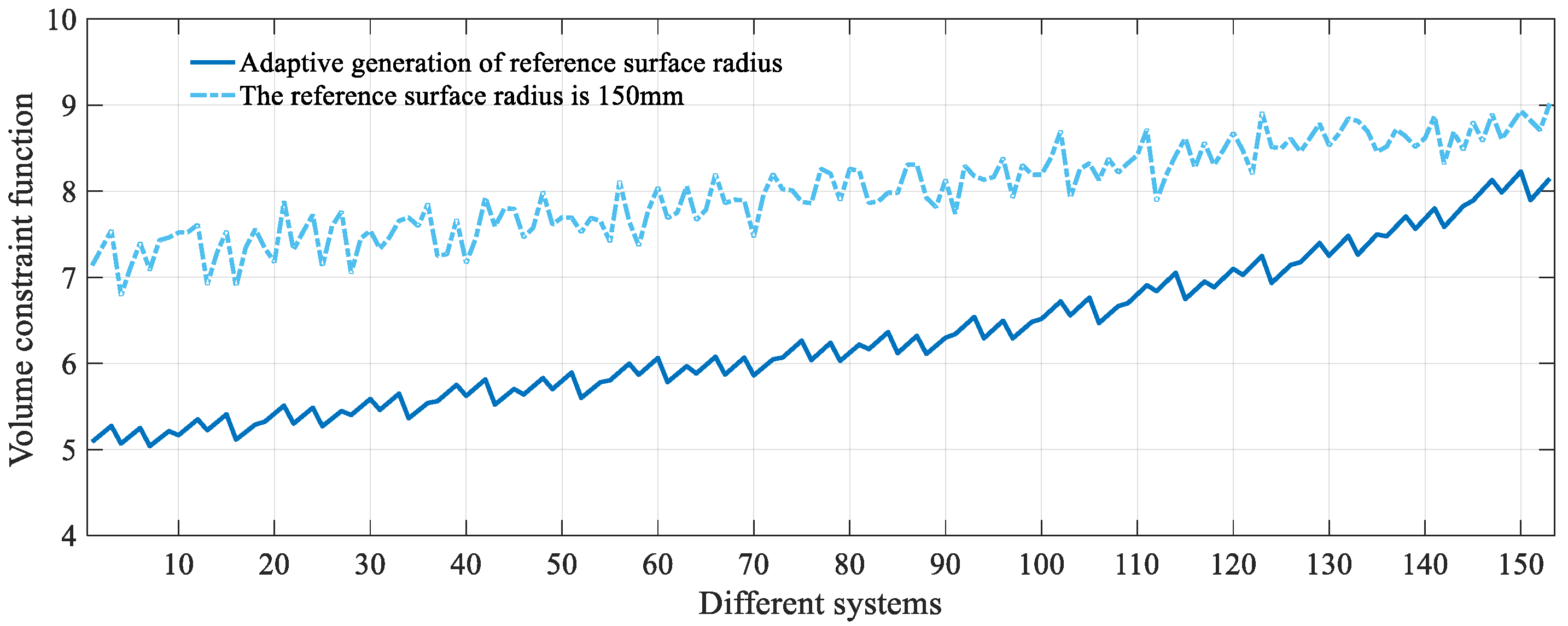
In this experiment, the dataset was constructed using the method proposed in this paper, with the design requirements outlined in Table 1. To create the input set for the dataset, the number of samples for the entrance pupil diameter, F-number, and FOV were set to 17, 3, and 3, respectively, resulting in a total of 153 samples. The minimum value of Equation (8) was obtained using the simulated annealing method, which was then used to construct the output set. Nine unobscured three-mirror imaging systems were randomly selected from the dataset, as shown in Figure 4. The quality of the dataset was visually assessed through the analysis of the layout diagrams. It can be observed that the mirrors in all nine systems were well-aligned with the cylindrical reference surface, and rays from different FOVs were focused near the ideal image point. This indicates that the unobscured three-mirror systems in the dataset met the requirements for easy fabrication and demonstrated fine imaging quality.
The dataset’s volume and structural design were quantitatively evaluated using the volume constraint function (Equation (1)), fabrication constraint function (Equation (5)), and error function (Equation (8)). A control group of 153 systems, with the same design requirements and input set but with the radius of the cylindrical reference surface fixed at 150 mm, was used for comparison. These systems were generated through a simulated annealing method, with the objective function f = argmin(E + C + Q). The comparison results are shown in Figure 5, Figure 6 and Figure 7, where the x-axis represents the system number of different unobscured three-mirror systems. These systems are arranged in ascending order of entrance pupil diameter. For example, the design requirements for the first system in the group are entrance pupil diameter of 80 mm, F-number of 3, and FOV of 2° × 2°; for the second system, the entrance pupil diameter is 80 mm, F-number is 3, and FOV is 3° × 3°; and for the last system, the entrance pupil diameter is 100 mm, the F-number is 3.5, and the FOV is 4° × 4°. In Figure 7, the error function values for the unobscured systems generated using the method proposed in this study are shown in odd rows, while for systems with the same design requirements but with the reference cylindrical radius fixed are shown in even rows. The row and column numbers decrease as the entrance pupil size decreases. For instance, the first system in the first row from the left has design requirements where the entrance pupil diameter is 80 mm, the F-number is 3, the FOV is 2° × 2°, and so on. It follows that:
(1)
When adaptive determination of the reference circle radius was used to construct the dataset, the mean volume of the 153 sets of unobscured three-mirror systems was found to be 6.29 L, with a maximum value of 8.23 L, a minimum value of 5.04 L, and a standard deviation of 0.84. When the radius of the reference circle was fixed at 150 mm, the mean volume, maximum value, minimum value, and standard deviation were found to be 8.00 L, 9.02 L, 6.79 L, and 0.51, respectively. When the reference circle radius was fixed, the range of volume variation was smaller, and the trend was more stable. This was due to the fixed reference circle radius, which restricted the adjustment range of distances between mirrors but also limited the possibility of achieving smaller distances between mirrors. When the method proposed in this study was used to construct the dataset, a larger variation in system volume was observed. This was because, when the system focal length was smaller, the system was better suited to a smaller reference circle radius, allowing for the possibility of obtaining smaller distances between mirrors, and thus smaller volume systems.
(2)
In the systems generated using the method proposed in this study for constructing the dataset, the variation range of the fabrication constraint function was found to be 2.09–3.74, with a standard deviation of 0.38 and a mean of 2.88. When the radius of the reference circle was fixed, the variation range, standard deviation, and mean of the fabrication constraint were found to be 1.98–5.82, 0.50, and 2.73, respectively. Although the mean of the fabrication constraint function for the systems obtained using the method proposed in this study was slightly higher than that of the systems obtained with a fixed reference circle radius, the variation range of the fabrication constraint function values in the systems generated by this method was smaller, with the maximum value being less than the maximum value when the reference circle radius was fixed. Furthermore, the trend was more stable. When the reference circle radius was fixed, the fluctuation of the fabrication constraint was found to be greater.
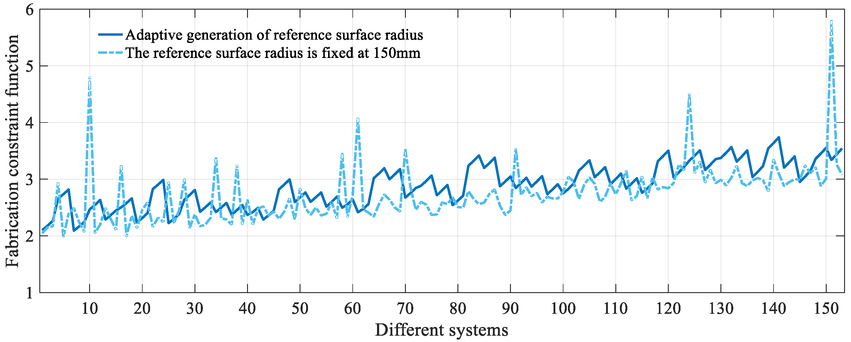
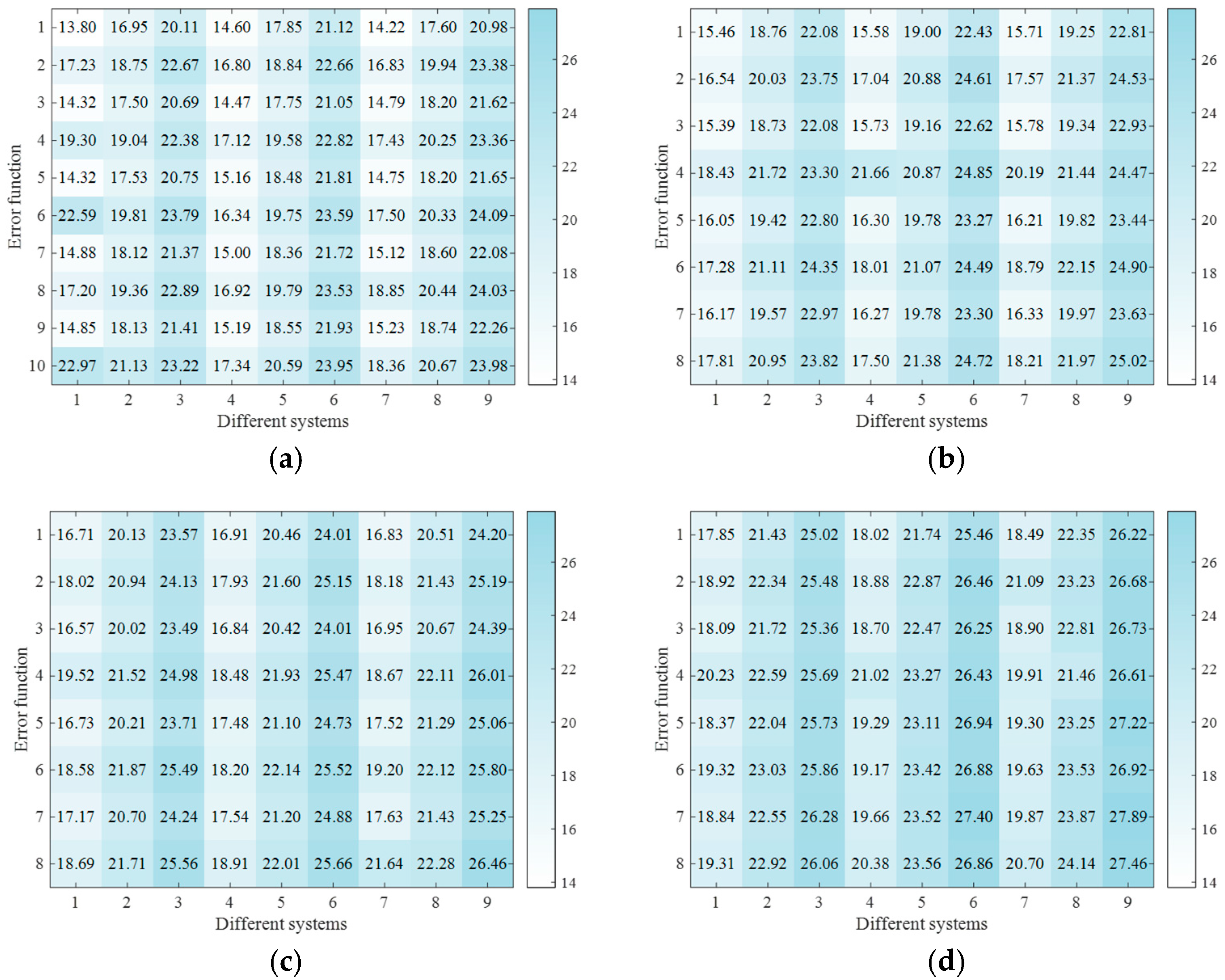
(3)
For the systems generated using the dataset construction methods proposed in this study and with a fixed reference circle radius, the mean values of the error function were found to be 20.05 and 21.66, respectively. When the focal length was relatively short, the error values of the systems obtained using the method proposed in this study were lower, with the difference being more pronounced compared to the fixed reference circle radius method. As the focal length increased, the overall error values of the systems obtained using the proposed method continuously increased, with some individual values exceeding those of the systems obtained using the fixed reference circle radius method. This was attributed to the fact that, at larger focal lengths, the reduction in system volume often leads to a decrease in imaging quality and an increase in the fabrication constraint function values. However, the maximum overall errors obtained using the method proposed in this study and the fixed reference circle radius method were 27.89 and 27.46, respectively, with a difference of only 0.43. This indicates that the method proposed in this study still effectively balances the relationship between system volume, assembly constraints, and imaging quality.
Therefore, the dataset construction method proposed in this paper, based on the adaptive reference circle radius, demonstrates greater advantages in terms of system volume, fabrication constraints, and error values, compared to the method with a fixed reference circle radius. Systems constructed using the adaptive method are capable of dynamically generating reference circle radii that better conform to the small volume constraints, thereby achieving smaller mirror distances and a more compact system design.

3.2. Model Training and Testing

The SVR model was trained with a maximum of 2000 iterations, and five-fold cross-validation was used to divide the training and testing sets. After training, the predictive capability of the SVR model was assessed. Nine sets of design requirements were randomly generated, and the trained SVR model was used for prediction. The resulting layouts for the nine unobscured three-mirror imaging systems are shown in Figure 8. It can be observed that the mirrors of the nine systems are well-aligned with the cylindrical reference surface, with no obscurations occurring, and the rays converge at the image plane. The error function values for these nine systems were calculated to be 20.52, 19.05, 22.71, 15.67, 22.94, 17.07, 21.96, 17.56, and 17.26, respectively. These values fall within the range of 15 to 23, which is consistent with the error function range obtained through the search method (Figure 7), indicating that the predicted results meet the design requirements. The imaging quality function values for these systems were 10.60, 10.27, 13.53, 8.03, 12.11, 8.54, 11.44, 9.01 and 7.73, respectively. It can be observed that the way rays converge is most influenced by the FOV. For example, in Figure 8c,e, where the F-number is the same, the entrance pupil diameter of (e) is larger, but due to the smaller FOV in (e), the rays converge better, with a difference of 1.42. The convergence of rays is secondly influenced by the entrance pupil diameter. For instance, in Figure 8b,g, where the FOV is the same and the F-numbers are similar, the system in Figure 8b has a smaller entrance pupil diameter and better imaging quality, with a difference of 1.17. The influence of the F-number on ray convergence is the least. By comparing Figure 8f,h, it can be seen that both systems have the same FOV and similar entrance pupil diameters. The system in Figure 8f has a smaller F-number and better convergence, but it is only slightly superior to the system in Figure 8h by 0.47. This is because the FOV determines the angular extent of observation. A larger FOV means more angles of rays are received, making it more difficult to converge the rays. The entrance pupil diameter affects the amount of light flux; smaller light flux means higher concentration of rays, which facilitates convergence. The F-number typically controls the system’s brightness and has a relatively smaller effect on ray convergence. Therefore, the role of the F-number in convergence is not significant. Additionally, since the system’s focal length is the product of the entrance pupil diameter and F-number, it can be seen that, for systems with the same FOV, smaller focal lengths result in better convergence (as seen in the comparison between Figure 8b,e). This is because systems with smaller focal lengths are more likely to have smaller volumes, thus causing less sacrifice in imaging quality. In contrast, systems with larger focal lengths need to sacrifice more imaging quality to achieve a smaller volume. Although the values of the imaging quality function differ, they all fall within the range of 7–14. Furthermore, the rays in all FOVs in Figure 8 converge on the image plane, demonstrating that the trained SVR model effectively balances multiple design constraints.
Two sets of unobscured three-mirror systems from Figure 8 were randomly selected, and the improved W-W method was used to obtain discrete points, which were then automatically fitted to generate freeform unobscured three-mirror systems. The design results are shown in Figure 9. It has been observed that the imaging quality of the systems has further improved, while the positions and tilt angles of the mirrors remain the same, indicating that the manufacturability is still maintained.
Finally, optical simulation software was used to assist in the optimization and verify the potential of the optimization process for the unobscured three-mirror system generated using the method proposed in this study. Optical simulation Zemax OpticStudio 20.3.2 was employed to optimize the two unobscured three-mirror systems with freeform surfaces shown in Figure 9. To ensure that the positions and tilt angles of the mirrors remained unchanged, the first three higher-order coefficients of the freeform surfaces were set to zero. The optimized results are shown in Figure 10 and Figure 11. It can be observed that after optimization, the imaging quality of both systems improved. The RMS radii for the two systems ranged from 5.92 μm to 9.97 μm and from 10.56 μm to 19.82 μm, respectively, both of which are smaller than typical detector pixel sizes [12,13]. The maximum field curvatures were 0.11 mm and 0.28 mm, and the maximum distortions were approximately 0.97% and 0.80%, respectively. The MTF curves at 50 lp/mm for both systems were greater than 0.6. These results demonstrate that the optimized systems are capable of achieving near-diffraction-limited imaging performance. This suggests that the small-volume unobscured three-mirror imaging systems generated using the proposed method have significant optimization potential. With the freeform unobscured three-mirror systems as a base, designers only need to perform minimal surface shape optimization using optical software to achieve an unobscured three-mirror imaging system close to the diffraction limit.

4. Conclusions

This study proposes a method for the adaptive generation of small volume and easy fabrication unobscured three-mirror systems based on machine learning. The method can automatically generate a freeform unobscured three-mirror system that is easy to fabricate and lightweight, based on design requirements. First, an adaptive parameter search method is designed with which a dataset is constructed. Next, an SVR model is trained and is used to generate the systemic parameters according to the design requirements. Finally, using the parameters generated by the trained SVR model as input, the improved W-W method is applied to automatically obtain discrete points and fit these points into a freeform surface, thus obtaining the freeform unobscured three-mirror system. Experimental results show that compared to other systems without the adaptive method for obtaining the reference circle radius, the system obtained by the proposed method has a significant reduction in volume and effectively balances the relationship among volume, fabrication constraints, and imaging quality. In addition, the system predicted by the trained SVR model demonstrates excellent easy fabrication characteristics and optimization potential. In future research, the direct output of freeform unobscured three-mirror systems with high imaging quality will be considered using machine learning models.

Author Contributions

Conceptualization, Y.S. and Y.W.; methodology, Y.S.; software, Y.S.; resources, Y.W. and J.Z.; writing—original draft preparation, Y.S.; writing—review and editing, Y.W. and Y.S.; supervision, Y.W.; funding acquisition, Y.W. and J.Z. All authors have read and agreed to the published version of the manuscript.

Funding

This research was funded by the National Natural Science Foundation of China, grant number 62373084.

Institutional Review Board Statement

Not applicable.

Informed Consent Statement

Not applicable.

Data Availability Statement

The original contributions presented in this study are included in the article. Further inquiries can be directed to the corresponding author.

Conflicts of Interest

The authors declare no conflicts of interest.

References

  1. Yang, T.; Xu, H.; Zhou, L.; Cheng, Y.; Wu, Z.; Shang, S.; Cheng, D.; Wang, Y. Design of a dual-focal-plane head-up display system using double freeform mirrors. Appl. Opt. 2024, 63, 8204–8211. [Google Scholar] [CrossRef]
  2. Xu, C.; Lai, X.; Cheng, D.; Wang, Y.; Wu, K. Automatic optical path configuration variation in off-axis mirror system design. Opt. Express 2019, 27, 15251–15261. [Google Scholar] [CrossRef] [PubMed]
  3. Wang, Y.; Yang, T.; Lyu, X.; Cheng, D.; Wang, Y. Ultra-simplified and low-cost head-up display system enabled by freeform holographic element. Opt. Laser Technol. 2024, 178, 111253. [Google Scholar] [CrossRef]
  4. Xu, H.; Yang, T.; Cheng, D.; Wang, Y. Compact freeform near-eye display system design enabled by optical-digital joint optimization. Front. Phys. 2024, 12, 1440129. [Google Scholar] [CrossRef]
  5. Bai, X.; Xu, B.; Ju, G.; Ma, H.; Zhang, C.; Wang, S.; Xu, S. Aberration compensation strategy for the radius of curvature error of the primary mirror in off-axis three-mirror anastigmatic telescopes. Appl. Opt. 2021, 60, 6199–6212. [Google Scholar] [CrossRef]
  6. Ji, H.; Zhu, Z.; Tan, H.; Shan, Y.; Tan, W.; Ma, D. Design of a high-throughput telescope based on scanning an off-axis three-mirror anastigmat system. Appl. Opt. 2021, 60, 2817–2823. [Google Scholar] [CrossRef]
  7. Liu, X.; Zhu, J. Automatic design method of starting points of freeform off-axis reflective imaging systems of small volume. Opt. Express 2022, 30, 7954–7967. [Google Scholar] [CrossRef]
  8. Qu, Z.; Zhong, X.; Zhang, K.; Wang, Y.; Li, L.; Liu, J.; Zeng, C. Automatic compact-volume design strategy for unobscured reflective optical systems based on conicoid surfaces. Opt. Commun. 2023, 533, 129304. [Google Scholar] [CrossRef]
  9. Rolland, J.P.; Davies, M.A.; Suleski, T.J.; Evans, C.; Bauer, A.; Lambropoulos, J.C.; Falaggis, K. Freeform optics for imaging. Optica 2021, 8, 161–176. [Google Scholar] [CrossRef]
  10. Li, Z.; Fang, F.; Chen, J.; Zhang, X. Machining approach of freeform optics on infrared materials via ultra-precision turning. Opt. Express 2017, 25, 2051–2062. [Google Scholar] [CrossRef]
  11. Li, Z.; Liu, X.; Fang, F.; Zhang, X.; Zeng, Z.; Zhu, L.; Yan, N. Integrated manufacture of a freeform off-axis multi-reflective imaging system without optical alignment. Opt. Express 2018, 26, 7625–7637. [Google Scholar] [CrossRef] [PubMed]
  12. Zheng, X.; Li, Z.; Zhang, X.; Fang, F. Manufacturing-constrained optical design methodology for cylindrical freeform reflective imaging system. Opt. Express 2018, 26, 22547–22562. [Google Scholar] [CrossRef] [PubMed]
  13. Sun, Y.; Sun, Y.; Chen, X.; Wang, F.; Yan, X.; Zhang, X.; Cheng, T. Design of a free-form off-axis three-mirror optical system with a low f-number based on the same substrate. Appl. Opt. 2022, 61, 7033–7040. [Google Scholar] [CrossRef] [PubMed]
  14. Sun, Y.; Wei, Y.; Chen, S.; Zhao, J. Fast starting point generation method for unobscured two-mirror imaging systems with large field-of-views. Optik 2023, 288, 171159. [Google Scholar] [CrossRef]
  15. Yang, T.; Cheng, D.; Wang, Y. Direct generation of starting points for freeform off-axis three-mirror imaging system design using neural network based deep-learning. Opt. Express 2019, 27, 17228–17238. [Google Scholar] [CrossRef]
  16. Chen, W.; Yang, T.; Cheng, D.; Wang, Y. Generating starting points for designing freeform imaging optical systems based on deep learning. Opt. Express 2021, 29, 27845–27870. [Google Scholar] [CrossRef]
  17. Mao, B.; Yang, T.; Xu, H.; Chen, W.; Cheng, D.; Wang, Y. FreeformNet: Fast and automatic generation of multiple-solution freeform imaging systems enabled by deep learning. Photonics Res. 2023, 11, 1408–1422. [Google Scholar] [CrossRef]
  18. Sun, Y.; Wei, Y.; Zhang, Y.; Zhao, J. Automated generation of easy-assembly off-axis three-mirror imaging systems based on few-shot machine learning. Appl. Opt. 2025, 64, 1068–1077. [Google Scholar] [CrossRef]
  19. Yang, T.; Zhu, J.; Jin, G. Compact freeform off-axis three-mirror imaging system based on the integration of primary and tertiary mirrors on one single surface. Chin. Opt. Lett. 2016, 14, 060801. [Google Scholar] [CrossRef]
  20. Sun, Y.; Wei, Y.; Zhao, J. Adaptive design of long-focal-length freeform off-axis reflective space cameras with lightweight and integration of primary/tertiary mirror. Front. Phys. 2024, 12, 1481131. [Google Scholar] [CrossRef]
  21. Sun, Y.; Wei, Y.; Di, X.; Zhao, J. Automatic generation method for long-focal-length unobscured freeform optical systems with small volume. Appl. Opt. 2024, 63, 3702–3711. [Google Scholar] [CrossRef] [PubMed]
  22. Gambella, C.; Ghaddar, B.; Naoum-Sawaya, J. Optimization Problems for Machine Learning: A Survey. Eur. J. Oper. Res. 2021, 290, 807–828. [Google Scholar] [CrossRef]
  23. Islam, M.; Park, J. Predicting PAHs removal from contaminated soil via subcritical water extraction using support vector regression. Environ. Eng. Res. 2025, 30, 240122. [Google Scholar] [CrossRef]
  24. Miñano, J.; Benítez, P.; Narasimhan, B. Freeform aplanatic systems as a limiting case of SMS. Opt. Express 2016, 24, 13173–13178. [Google Scholar] [CrossRef]
  25. Nie, Y.; Mohedano, R.; Benítez, P.; Chaves, J.; Miñano, J.C.; Thienpont, H.; Duerr, F. Multifield direct design method for ultrashort throw ratio projection optics with two tailored mirrors. Appl. Opt. 2016, 55, 3794–3800. [Google Scholar] [CrossRef]
  26. Yang, T.; Jin, G.; Zhu, J. Automated design of freeform imaging systems. Light Sci. Appl. 2017, 6, e17081. [Google Scholar] [CrossRef]
  27. Yang, T.; Zhu, J.; Wu, X.; Jin, G. Direct design of freeform surfaces and freeform imaging systems with a point-by-point three-dimensional construction-iteration method. Opt. Express 2015, 23, 10233–10246. [Google Scholar] [CrossRef]
  28. Zhang, B.; Jin, G.; Zhu, J. Towards automatic freeform optics design: Coarse and fine search of the three-mirror solution space. Light Sci. Appl. 2021, 10, 65. [Google Scholar] [CrossRef]
  29. Yang, T.; Cheng, D.; Wang, Y. Freeform imaging spectrometer design using a point-by-point design method. Appl. Opt. 2018, 57, 4718–4727. [Google Scholar] [CrossRef]
  30. Volatier, J.; Druart, G. Differential method for freeform optics applied to two-mirror off-axis telescope design. Opt. Lett. 2019, 44, 1174–1177. [Google Scholar] [CrossRef]
  31. Cheng, D.; Wang, Y.; Hua, H. Freeform optical system design with differential equations. Proc. SPIE 2010, 7849, 78490X. [Google Scholar]
  32. Chen, S.; Wei, Y.; Sun, Y.; Zhao, J. Design of off-axis three-mirror freeform systems based on refined W-W differential equations. Appl. Opt. 2023, 62, 3892–3903. [Google Scholar] [CrossRef]
Figure 1. Schematic diagram of the optical system.
Photonics 12 00405 g001
Figure 2. Schematic diagram of the SVR training process.
Photonics 12 00405 g002
Figure 3. Flow chart of the design method in this study.
Photonics 12 00405 g003
Figure 4. Layout diagrams of nine unobscured three-mirror systems in the dataset. (a) ED = 85, F = 3.5, FOV = 3° × 3°; (b) ED = 96.25, F = 3, FOV = 4° × 4°; (c) ED = 82.5, F = 3.5, FOV = 4° × 4°; (d) ED = 97.5, F = 3.5, FOV = 3° × 3°; (e) ED = 90, F = 3, FOV = 3° × 3°; (f) ED = 100, F = 3.25, FOV = 4° × 4°; (g) ED = 95, F = 3.25, FOV = 4° × 4°; (h) ED = 92.5, F = 3, FOV = 2° × 2°; (i) ED = 87.5, F = 3.25, FOV = 2° × 2°.
Photonics 12 00405 g004
Figure 5. Value of volume constraint function.
Photonics 12 00405 g005
Figure 6. Value of fabrication constraint function.
Photonics 12 00405 g006
Figure 7. Value of error function. (a) Entrance pupil diameter: 80–85 mm. (b) Entrance pupil diameter: 86.25–90 mm. (c) Entrance pupil diameter: 91.25–95 mm. (d) Entrance pupil diameter: 95.25–100 mm.
Photonics 12 00405 g007
Figure 8. Layout diagrams of unobscured three-mirror systems predicted using the trained SVR model. (a) ED = 95.5, F = 3.2, FOV = 2.8° × 2.8°; (b) ED = 88, F = 3, FOV = 3° × 3°; (c) ED = 92, F = 3.5, FOV = 3.6° × 3.6°; (d) ED = 82, F = 3.4, FOV = 2.2° × 2.2°; (e) ED = 98, F = 3.5, FOV = 3° × 3°; (f) ED = 86, F = 3, FOV = 2.5° × 2.5°; (g) ED = 96, F = 3.25, FOV = 3° × 3°; (h) ED = 85.5, F = 3.4, FOV = 2.5° × 2.5°; (i) ED = 94, F = 3.2, FOV = 2° × 2°.
Photonics 12 00405 g008
Figure 9. Layout of the freeform unobscured three-mirror systems. (a) ED = 82, F = 3.4, FOV = 2.2° × 2.2°; (b) ED = 96, F = 3.25, FOV = 3° × 3°.
Photonics 12 00405 g009
Figure 10. Design results for freeform three-mirror reflective system after optimization. (a) Layout; (b) MTF curve; (c) spot diagram; (d) field curvature and distortion.
Photonics 12 00405 g010
Figure 11. Design results for freeform three-mirror reflective system after optimization. (a) Layout; (b) MTF curve; (c) spot diagram; (d) field curvature and distortion.
Photonics 12 00405 g011
Table 1. Specifications of the optical systems.
ParameterSpecifications
Entrance pupil diameter80–100 mm
F-number3–3.5
Field-of-view2° × 2°–4° × 4°
The number of mirrors3
Work spectrum380–780 nm
Disclaimer/Publisher’s Note: The statements, opinions and data contained in all publications are solely those of the individual author(s) and contributor(s) and not of MDPI and/or the editor(s). MDPI and/or the editor(s) disclaim responsibility for any injury to people or property resulting from any ideas, methods, instructions or products referred to in the content.

