Article

Generating Large Time–Bandwidth Product RF-Chirped Waveforms Using Vernier Dual-Optical Frequency Combs

by
Mohammed S. Alshaykh
Electrical Engineering Department, College of Engineering, King Saud University, Riyadh 11421, Saudi Arabia
Photonics 2025, 12(7), 700; https://doi.org/10.3390/photonics12070700
Submission received: 3 May 2025 / Revised: 3 July 2025 / Accepted: 4 July 2025 / Published: 11 July 2025

Abstract

Chirped radio-frequency signals are essential waveforms in radar systems. To enhance resolution and improve the signal-to-noise ratio through higher energy transmission, chirps with high time–bandwidth products are highly desirable. Photonic technologies, with their ability to handle broad electrical bandwidths, have been widely employed in the generation, filtering, processing, and detection of broadband electrical waveforms. In this work, we propose a photonics-based large-TBWP RF chirp generator utilizing dual optical frequency combs with a small difference in the repetition rate. By employing dispersion modules for frequency-to-time mapping, we convert the spectral interferometric patterns into a temporal RF sinusoidal carrier signal whose frequency is swept through the optical shot-to-shot delay. We derive analytical expressions to quantify the system’s performance under various design parameters, including the comb repetition rate and its offset, the second-order dispersion, the transform-limited optical pulse width, and the photodetector’s bandwidth limitations. We benchmark the expected system performance in terms of RF bandwidth, chirp duration, chirp rate, frequency step size, and TBWP. Using realistic dual-comb source parameters, we demonstrate the feasibility of generating RF chirps with a duration of 284.44 μ s and a bandwidth of 234.05 GHz, corresponding to a TBWP of 3.3 × 10 7 .

1. Introduction

Chirped microwave signals with large time-bandwidth products have become a cornerstone of modern radar systems that rely on pulse compression techniques. Increasing the time aperture without compromising waveform fidelity remains one of the central challenges in waveform generation. Large time–bandwidth product (TBWP) chirps are particularly critical for high-resolution radar systems such as Synthetic Aperture Radar, Ground Penetrating Radar, and Frequency-Modulated Continuous-Wave Radar [1,2]. Moreover, such chirps can extend the operational range of radar systems and improve sensitivity and false alarm rates by enabling the transmission of higher-energy waveforms, thereby enhancing the signal-to-noise ratio [3,4,5].
Photonics-based microwave generation is a promising candidate for applications requiring simultaneously a large bandwidth and low phase noise. Such methods are centered around optical frequency combs (OFCs), which have revolutionized the field of frequency metrology and have since found applications across numerous other disciplines. In the time domain, a coherent optical frequency comb appears as a periodic train of ultrashort pulses with a temporal period of 1 / f r , where f r denotes the repetition frequency. In the frequency domain, its Fourier transform yields a discretized optical spectrum consisting of evenly spaced comb lines separated by f r . The optical frequency of the n-th comb line is given by f n = f ceo + n · f r , indicating that each line is phase-coherently locked to two microwave frequencies: the repetition rate f r and the carrier-envelope offset frequency (CEO) f ceo . Full stabilization of the optical comb requires locking both f ceo and f r . This capability was leveraged by research groups worldwide in the late 1990s, culminating in the realization of optical atomic clocks that redefined the limits of precision timekeeping. A primary technical challenge at the time was CEO stabilization, which necessitated broadband, octave-spanning combs, followed by a nonlinear f - 2 f self-referencing process.
In microwave photonics, engineered optical pulses or pulse trains are used to generate RF signals through direct photodetection. Alternatively, a microwave signal can be upconverted to the optical domain—typically using an electro-optic modulator—processed photonically, and subsequently downconverted back to the electrical domain via photodetection. Numerous photonics-based RF signal-processing functionalities have been demonstrated, including stimulated Brillouin suppression in long-haul links [6,7], tunable RF filters [8,9], optical beamforming and true-time-delay systems [10], RF subsampling and channelization [11,12,13,14,15], broadband wireless communication [16], and coherent optical communication [17].
Microwave signal generation, on the other hand, can be broadly classified into two categories. The first category focuses on generating high-purity, low-phase-noise single-frequency RF tones, which are of paramount importance in applications such as precision timing, frequency metrology, and radio astronomy.
Several techniques have been developed for this purpose, including heterodyning of two highly stable lasers [18,19], optoelectronic oscillators based on high-quality optical resonators [20,21], and frequency-division techniques using either electro-optic frequency division or mode-locked laser-based OFCs [22]. The frequency-division approaches transfer the stability of the optical domain—originating either from a fully referenced octave-spanning comb or from a stabilized comb line f n locked to a high-quality optical cavity—into the microwave regime.
Such methods provide state-of-the-art pure single-tone microwaves with phase noise below −173 dBc·Hz−1 at 10 kHz and impressive timing noise below 41 zs·Hz−1/2 at 12 GHz [23]. However, fully referencing an optical comb and developing rugged high-quality cavities is still a complicated task [24,25]. Additionally, these methods are not suitable for tunable broadband microwave synthesis.
The second category of microwave generation focuses on the generation of arbitrary broadband microwave waveforms that are often mediated by the processing of an OFC. The processing or manipulation of the comb is often performed using Fourier-domain pulse shapers. The key idea in Fourier-domain pulse shapers is based on spatially separating Fourier components (wavelengths) using a spectral disperser (e.g., grating or prism), followed by a spatial light modulator to manipulate the phase and amplitude of the diffracted wavelengths. Subsequently, the Fourier components are recombined using a second grating, outputting arbitrarily tailored optical pulses [26,27]. The photodetection of the said optical pulses transfers their intensity profile to the microwave domain, generating a tailored voltage waveform. This has allowed, for example, the use of fast optical switches followed by spectrally multiplexed pulse shapers to perform a rapid update of RF waveforms [28]. In [28], two independent lasers followed by switches were used; however, the setup can be further simplified using a tunable DBR laser [29]. Several variants of these concepts ensued [30]; nevertheless, such schemes ultimately suffered from unfavorable scaling. Going beyond two waveforms to N waveforms required an N-factor increase in optical switching elements and more sophisticated electrical control sequences. To overcome this limitation, the authors of [31] utilized the concept of frequency-to-time mapping (FTM) as a replacement for the switching elements. Four shaped and spectrally separated OFCs were generated and then sent through a dispersive element—a spool of fiber, for example. As a result of dispersion, each frequency travels at a different velocity; thus, the spectral multiplexing is transformed into temporal multiplexing, allowing switching times within a clock period of 200 ps between four channels.
In contrast, FTM has also been used to directly map a single arbitrary-shaped optical pulse into the microwave domain. Typically, a broadband mode-locked laser generating ∼100 fs-scale pulses at repetition rates on the order of tens of MHz is manipulated to produce arbitrary optical waveforms with time scales ranging from femtoseconds to picoseconds. Using FTM, these waveforms are stretched into nanosecond time apertures, generating microwave bursts with several gigahertz bandwidths [32,33]. However, it should be noted that FTM produces a linearly scaled replica of the optical frequency components only in the far-field limit [34]. This limitation can be mitigated through pre-distortion of the amplitude and phase of the optical pulse under so-called near-field conditions, a technique that was used to demonstrate downchirp waveforms spanning from baseband up to 45 GHz with a time aperture of 4.5 ns [35]. Although these results are impressive, accessing the microwave W-band (approximately 70–110 GHz)—which is of great interest for short-range wireless communications and radar applications—remains challenging. An effective technique to overcome this limitation involves the use of an imbalanced interferometer: by splitting the pulsed laser into two arms, where one arm contains a pulse shaper and the other a delay line, the recombined pulses form a sinusoidally modulated spectrum. After FTM, this modulation sets the center frequency of the generated RF waveform. Using this concept, a W-band chirped waveform with a 15 ns time aperture and a TBWP of 600 was generated and successfully demonstrated in a ranging experiment, achieving an ultra-high ranging resolution of 3.9 mm [36]. In addition to ranging, this photonics-based RF arbitrary waveform generator was used for channel sounding and multipath compensation in ultra-wideband wireless communication transmissions [37].
A different class of waveform generators broadly relies on the concepts of photonic multiplication and/or heterodyning. These setups typically focus on generating a specific waveform, often a linear chirp. The most basic example of heterodyne generation is the beating of two lasers, either independent or filtered lines from an optical frequency comb (OFC). While using independent lasers is straightforward, the generated signal is incoherent unless the two lasers are phase-locked. Photonic multiplication often relies on electro-optic modulators. In its simplest form, a continuous-wave (CW) seeded electro-optic phase modulator driven by a sinusoidal RF tone produces a comb-like optical spectrum following a Bessel function distribution, with comb-line spacing equal to the modulation frequency. The comb lines can be expressed as f 0 + m f RF , where f 0 is the optical carrier frequency, f RF is the modulation frequency, and m is an integer. By filtering the m-th sideband, the photodetected RF signal becomes a multiplied version of the input RF tone. These concepts were combined to transform a 1 GHz chirp into a chirped signal extending from 27 to 33 GHz with a TBWP of 6000, which was utilized in a ranging experiment, achieving a resolution of 3.75 cm [38]. In a different architecture, a recirculating frequency-shifting loop was implemented to tailor chirps with bandwidths exceeding 28 GHz and a TBWP exceeding 1000 [39].
While the results achieved with FTM are impressive, the time aperture is ultimately limited by the pulse repetition frequency. Even in near-field FTM, the TBWP is constrained by the ratio of the RF bandwidth to the optical bandwidth, and improving this ratio in practice remains challenging. Additionally, higher-order dispersion terms distort the linearity of the chirp, particularly when large optical bandwidths are used. As for photonic multiplication techniques, although they are relatively simple, they are highly inefficient: often only a single sideband is utilized, meaning that only a small fraction of the optical power incident on the photodetector contributes to the targeted waveform generation. This leads to reduced RF gain, higher system power consumption, and a degraded link noise figure. In recirculating loops, an optical amplifier is typically used to compensate for the insertion loss of optical components. However, such amplifiers often exhibit noise figures of 5–7 dB, and the multi-pass nature of the loop accumulates noise, further degrading the fidelity of the generated waveforms.
Here, we propose the utilization of Vernier dual-OFCs. In Vernier dual-OFC systems, the two combs have a small difference in repetition rate ( f d ). In the time domain, this small difference leads to a shot-to-shot incremental delay between the two pulses. This phenomenon is very well established and forms the basis of dual-comb spectroscopy and LIDARs. Dual-comb systems can be developed based on either electro-optic combs or mode-locked lasers, depending on the required repetition rate and pulse width. Within the context of chirped waveform generation, this concept is a hybrid of the aforementioned FTM imbalanced interferometer techniques, with the critical difference that the delay is now automatically incremented from shot to shot. As mentioned previously, this delay results in a modulated spectrum, which can be transformed to the time domain through FTM. After FTM, the delay between the pulses is transformed into a central carrier frequency in the RF domain. Since the delay is automatically swept, the carrier frequency is swept accordingly. An important advantage here is that the chirp duration is now set by the interferogram duration ( 1 / f d ) and the pulse repetition rate, promising orders-of-magnitude improvement in the TBWP. Equally important, the step in the delay is fundamentally linear and is tightly locked by the synchronized pulse trains, leading to a highly linear chirp.

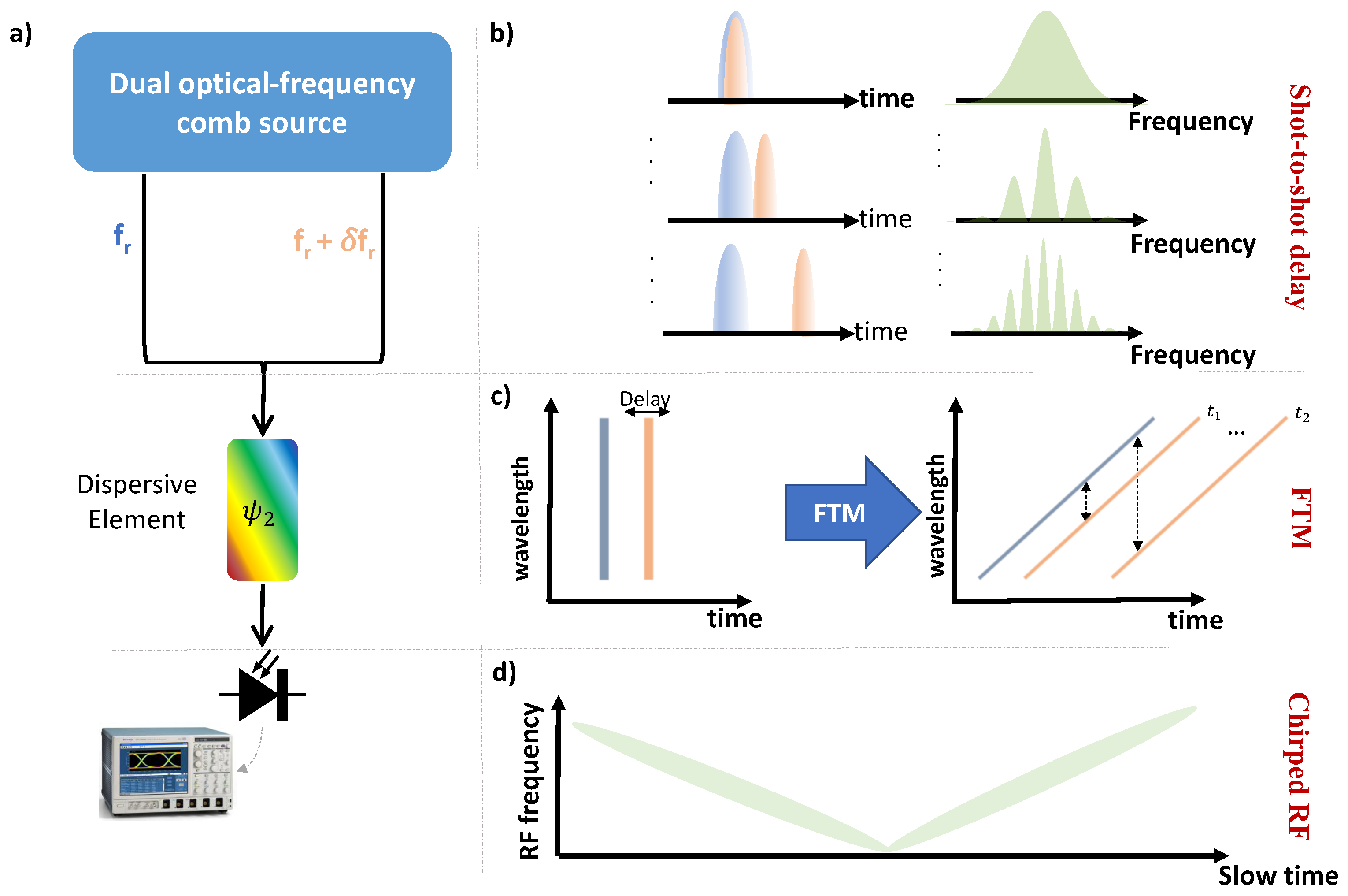
2. Concept and Theory

The main concept of this work combines Vernier dual-OFCs with frequency-to-time mapping. A conceptual diagram and a simplified system setup are shown in Figure 1. Two OFCs with repetition rates f r 1 and f r 2 = f r 1 + f d , where f d is a small offset, produce pulse trains that experience a shot-to-shot incremental delay equivalent to the difference in repetition periods, i.e., T i = 1 / f r 1 1 / f r 2 , which, for differences in the repetition rate much smaller than the repetition rate, can be approximated as f d / f r 1 2 . This evolving delay between successive pulse pairs results in a sinusoidally modulated optical spectrum, whose modulation frequency depends on the relative delay. Both pulse trains propagate through a dispersive element—such as a fiber spool, chirped fiber Bragg grating, diffraction grating, or prism—which temporally stretches the pulses, effectively mapping the spectral interference pattern into a time-domain sinusoidal waveform. This waveform is then photodetected and transferred to the microwave domain. The central frequency of the resulting RF waveform is swept as a consequence of the incremental delay introduced by the Vernier dual-comb interaction.
An alternative perspective is the so-called spectral focusing picture, commonly used in spectroscopy [27]. In this representation, a chirped optical pulse can be interpreted as having a frequency-dependent time delay. When two linearly chirped optical pulses are heterodyned on a photodetector, the resulting signal is de-chirped and downconverted to a central frequency that depends on the temporal offset between the pulses.
To derive a model for the proposed apparatus, we assume two identical optical pulses with a Gaussian envelope of a ( t ) = e x p ( t 2 / t p 2 ) , where t p is the root-mean-square (rms) pulse width corresponding to a full width at half maximum of 1.177 t p . Next, the pulses pass through a dispersion stage characterized by a quadratic dispersion profile. Assuming a second-order dispersion coefficient denoted by ψ 2 , the pulse envelope in the Fourier domain can be expressed as A c h ( ω ) = A ( ω ) · e x p ( i ω 2 ψ 2 ) . Equivalently, in the time domain, the resulting chirped temporal waveform can be represented as
a c h ( t ) = 1 1 j X e x p t 2 t p , c h 2 1 + j X
where X = 2 ψ 2 / t p 2 and t p , c h is the chirped waveform RMS pulse width, which can be linked to the dispersion and transform-limited pulse width through the following relationship
t p , c h = t p 1 + X 2
Writing the equation in terms of the experimental design parameters (i.e., t p , t p , c h , and ψ 2 ) provides an intuitive and direct link between the theory and experiments. After combining the pulse trains with the Vernier offset, i.e.,
a t o t a l ( t ) = a 1 , c h ( t ) + a 2 , c h ( t T i )
and photodetecting the combined field, the output voltage at the photodetector can be expressed as
u ( t ) | a 1 , c h ( t ) | 2 + | a 2 , c h ( t T i ) | 2 + v ( t )
The first two terms arise from the pulse trains of each comb independently. In the frequency domain, they form baseband signals, whose bandwidth depends on the chirped optical pulse width. Importantly, the power spectral density of these two terms remains unchanged with respect to the delay. The third term, denoted as v ( t ) , arises from the interference between the two pulse trains and is responsible for the complex dynamics relevant to chirp generation. It can be expressed as
v ( t ) = a 1 , c h * ( t ) a 2 , c h ( t T i ) + c . c .
= 1 1 + X 2 exp t 2 ( t T i ) 2 t p , c h 2 + j X t 2 ( t T i ) 2 t p , c h 2 + c . c .
Here, “c.c.” denotes the complex conjugate of the preceding term. It is more convenient to rewrite Equation (6) in terms of two time scales, a fast time t 1 2 f r , 1 2 f r and a slow time τ k f r k = 0 , ± 1 , ± 2 , , f r / ( 2 f d ) . The slow time increases with a step of one round-trip time ( 1 / f r ) and is bounded by the interferogram refresh rate (1/ f d ). Alternatively, this can be thought of as the number of round trips within each interferogram ( f r / f d ) multiplied by the round-trip time. Expressing the incremental delay as a function of the slow time T i ( τ ) = ( f d / f r ) τ , we rewrite Equation (6) as
v ( t , τ ) = 1 1 + X 2 exp t 2 ( t ( f d / f r ) τ ) 2 t p , c h 2 + j X t 2 ( t ( f d / f r ) τ ) 2 t p , c h 2 + c . c .

3. Results

To explore the design space and performance potential of the proposed system, we perform a parameter sweep over key design variables, including the transform-limited optical pulse width, the second-order dispersion, the repetition rate, and the repetition-rate offset. We analyze the impact of these parameters on critical performance metrics such as the chirp rate, frequency step size, time aperture, RF bandwidth, and resulting TBWP. Finally, we provide a realistic assessment of the achievable system performance by adopting the parameter values reported in experimentally demonstrated dual-comb systems, and we compare the resulting figures of merit to state-of-the-art high-TBWP waveform generation techniques.

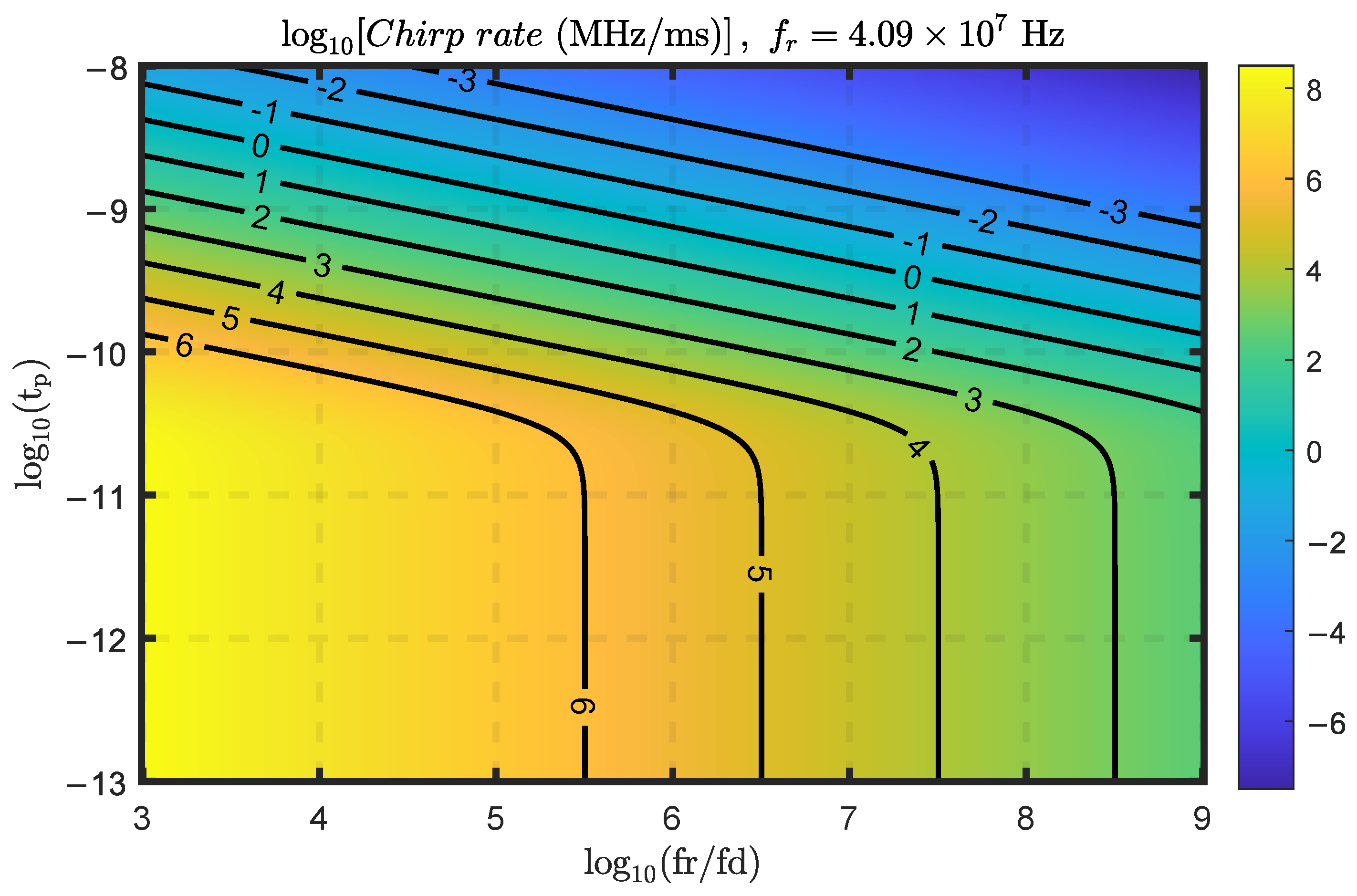
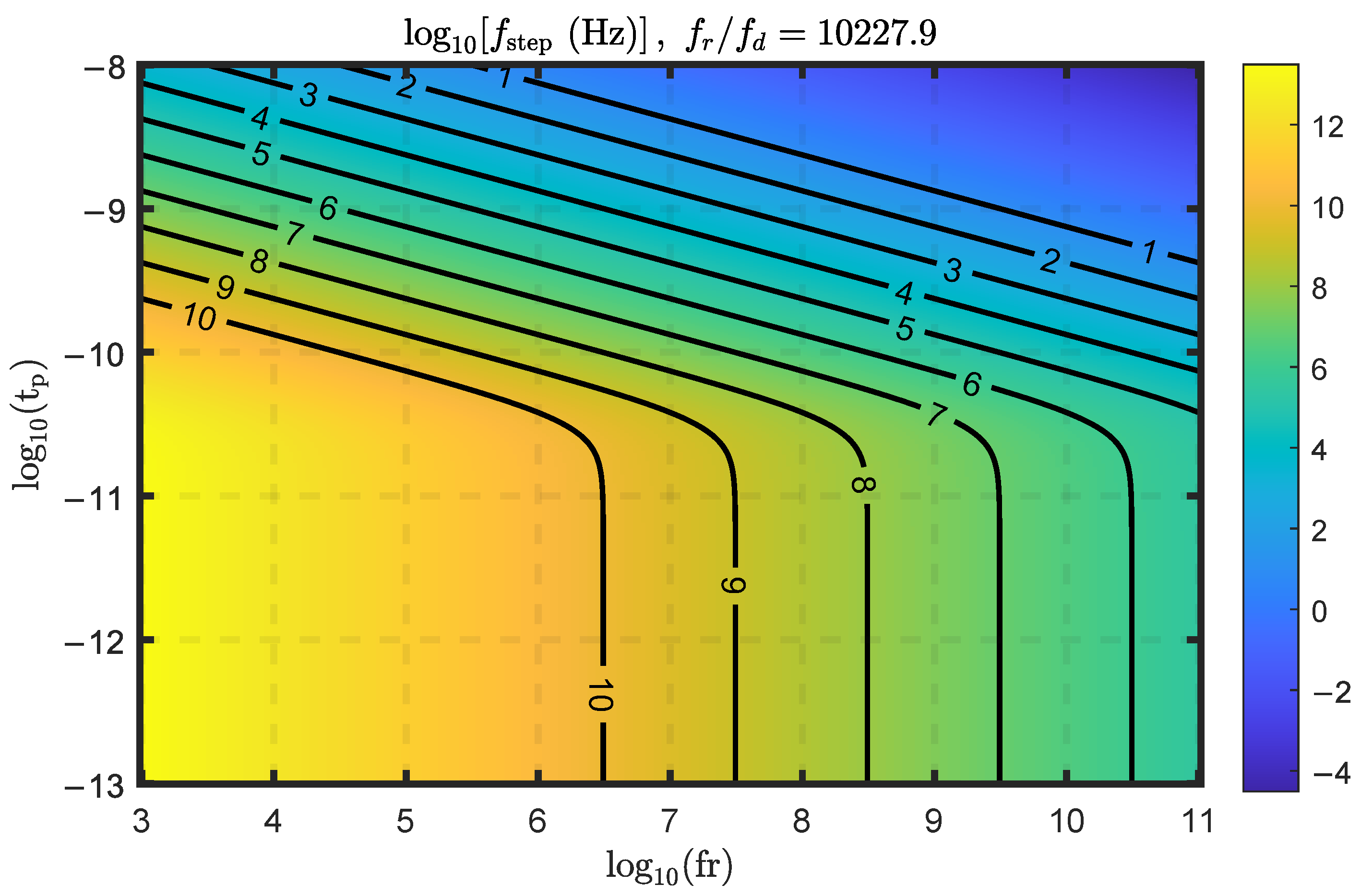
3.1. Chirp Rate and Frequency Step

From Equation (7), we can infer the instantaneous frequency of the signal from the phase of the exponential as the slope of the following equation
ω i n s t = ϕ ( t ) t = 2 X T i t p , c h 2 = 4 ψ 2 t p 4 + 4 ψ 2 2 f d f r τ
The chirp rate—in radians per second—depends on three main parameters: the dispersion, the difference in the repetition rate, and the repetition rate itself. In the limit where 4 ψ 2 / t p 2 is orders of magnitude smaller than one, we can approximate the slope as ( 4 ψ 2 f d ) / ( f r t p 4 ) , indicating that it scales linearly with both the dispersion ψ 2 and the Vernier difference f d , and inversely with the repetition rate and the square of the pulse width. This allows a greater level of flexibility, as the dispersion and Vernier difference are typically tunable parameters.
Figure 2 shows the chirp rate, as described in Equation (8), as a function of the transform-limited optical pulse width and the ratio of the repetition rate to the Vernier frequency ( f r / f d ), evaluated at a repetition rate of 40.9 MHz. The second-order dispersion, ψ 2 , is set to ψ 2 = 500 p s 2 throughout this section unless otherwise specified. The figure shows that at f r / f d smaller than 10 6 , sub-100 ps pulses yield extremely high chirp rates, THz/ms, which are undesirable practically.
In addition to the chirp rate, we must pay attention to the shot-to-shot discrete frequency step, which is simply the chirp rate multiplied by the round trip, or
ω s t e p = 4 ψ 2 t p 4 + 4 ψ 2 2 f d f r 2
showing that the step is inversely proportional to the square of the repetition rate. Figure 3 shows the frequency step as a function of the optical pulse width and the repetition rate at a fixed f r / f d of 10,227.9. While some design approaches can achieve large TBWPs, care must be taken to ensure that the resulting frequency resolution is sufficiently high for radar applications. It is evident that at sub-MHz repetition rates and sub-picosecond pulses, the frequency step may be unsuitable for many practical systems. For reference, electronic FMCW generators are often based on voltage-controlled oscillators (VCOs). Consider a high-bandwidth VCO covering 9–22 GHz with a tuning sensitivity of 600 MHz/V over a 20 V control range as a representative example. If such a VCO is driven by a 16-bit DAC or function generator, the voltage resolution would be 20 V / 2 16 305 μ V per step, resulting in a frequency step size of approximately 183 kHz . This example illustrates that, even with high-resolution control, the achievable frequency granularity may still be a limiting factor and provides a useful reference point for evaluating photonic counterparts. Nevertheless, the ability to tune the transform-limited pulse width through spectral filtering offers a large degree of flexibility to traverse this map.

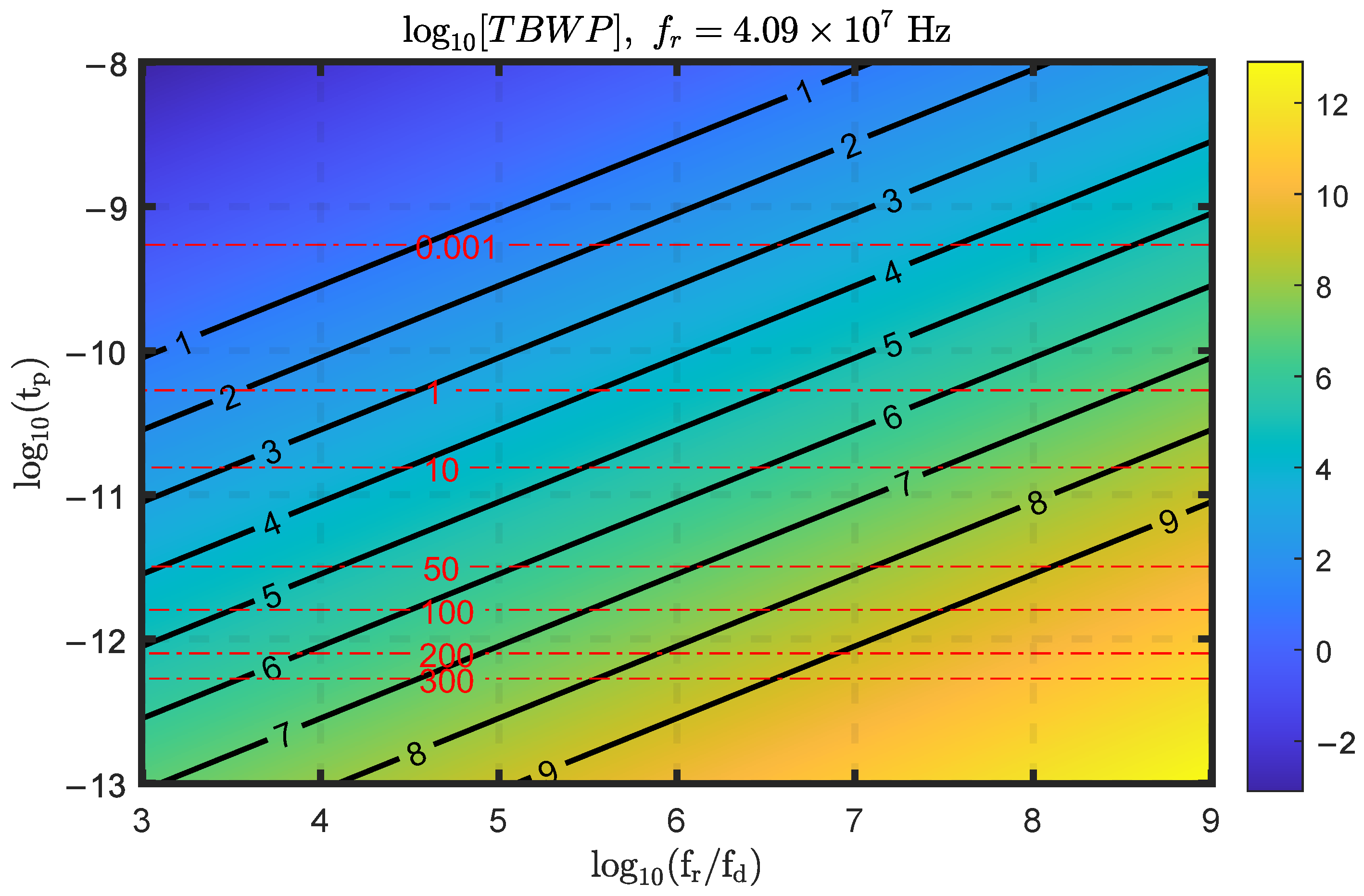
3.2. Time–Bandwidth Product

One of the most important and critical metrics of chirped signals is the time–bandwidth product. Generating RF chirps with high TBWPs results in greater temporal compression, yielding improved range resolution and allowing the transmission of higher energies, which results in better signal-to-noise ratios. To compute the TBWP, we need to determine the RF pulse width and chirp bandwidth.
From Equation (7), it is evident that the RF chirp decays exponentially with the slow time as exp ( f d / f r ) t p , c h τ 2 . Consequently, the rms pulse width of the chirped RF waveform is
t p r f , c h = ( f r / f d ) t p , c h
Essentially, this result shows that the RF waveform width is the original chirped optical pulse width scaled by the number of round trips per interferogram. Using this relation along with the chirp-rate equation (Equation (8)) to compute the RF chirp bandwidth, we can write the TBWP as
T B W P = 0.5 × Δ f r f × t p r f , c h = ψ 2 f r 2 π t p 2 f d
where the chirp bandwidth is calculated as Δ f r f = ω i n s t τ × t p r f , c h / 2 . The factor of one-half is included to account for positive and negative delays, which correspond to up and down chirp ramps. Note that this is the rms TBWP; the full width at half maximum product can be obtained as T B W P 3 d b = T B W P / 1 . 177 2 . Furthermore, we note that the instantaneous rms bandwidth is set by the chirped optical pulse width (i.e., Δ f i n s t = 0.441 2 / t p , c h ).
Figure 4 shows the TBWP as a function of both t p and f r / f d at a fixed repetition rate ( f r = 40.9 MHz). The TBWP ranges from 10 to 109, showing potentially unprecedentedly high TBWP values. However, this analysis does not take into account equipment limitations, which are mainly constrained by the bandwidth of the photodetector. To visualize this, we superimpose the expected chirp bandwidth on the same figure. Notably, we observe that even with a photodetector bandwidth of 50 GHz, which is commercially available, high TBWPs remain attainable.
While this analysis is informative, we further scrutinize the multidimensional design space by imposing practical conditions to highlight the practically possible scenarios. Namely, we impose four conditions:
  • The optical pulse width is smaller than the round-trip time ( t p , c h · f r ) < 0.25 .
  • The RF chirp bandwidth is smaller than 300 GHz Δ f r f < 300 GHz .
  • The shot-to-shot frequency step is less than 100 GHz f step < 100 GHz .
  • The chirp rate is greater than KHz/ms and smaller than THz/ms
    1 KHz / ms chirp rate 1 THz / ms .
Figure 5 shows the TBWP values for regions that satisfy the above conditions at different repetition rates. We see that as the repetition rate increases, the viable design space shrinks until it completely closes for values greater than 5.5 GHz. This analysis indicates that mode-locked lasers are a more suitable source for such experiments than Kerr microcombs, whose repetition rates are typically greater than 20 GHz. More importantly, this analysis shows that it is entirely feasible to reach a TBWP of 106 to 108 with this scheme using common 80 MHz repetition-rate mode-locked lasers.

3.3. Effects of the OFC’s Instabilities

Even though the characteristics of the generated RF-chirped waveforms in terms of the TBWP are attractive, it is important to assess whether the proposed apparatus is practically stable. The phase-noise characteristics of the generated waveform depend on the optical frequency comb’s (OFC’s) inherent phase noise and are also influenced by noise contributions from the amplifiers and photodetectors used in the system.
However, it is highly informative to consider the problem from an abstract perspective and assess how instabilities in the OFC affect the chirp’s linearity. Specifically, we examine how the frequency instability of the comb’s repetition rate, f d , and the frequency instability of the feedback loop that locks the two combs together, Δ f d , translate into instability in the instantaneous frequency of the chirp. From Equation (8), we find that
ω i n s t + Δ ω i n s t = 4 ψ 2 t p 4 + 4 ψ 2 2 f d + Δ f d f r + Δ f r τ
Expanding the fraction to the first order and equating the instability terms, the fractional frequency instability, i.e., Δ ¯ f = Δ f / f , can be expressed as
Δ ¯ ω i n s t = Δ ¯ f d Δ ¯ f r Δ ¯ f d Δ ¯ f r f r
This expression indicates that the fractional instability in the chirp rate follows that of the repetition-rate frequency-difference lock signal and the instability of the repetition rate, as well as a third term that depends on both. More critically, the chirp-rate instability tracks the dual-OFC’s fractional instabilities— Δ ¯ f d and Δ ¯ f r —without any amplifying coefficient. The repetition rates and their difference are typically photodetected and stabilized via feedback loops referenced to an oven-controlled quartz oscillator, which can achieve fractional frequency instabilities as low as 10 12 [25,40,41]. Instabilities in the OFC can be further reduced by two orders of magnitude or more using atomic frequency standards. Although the last term is multiplied by the repetition rate, it remains on the order of, or less than, the first two terms for repetition rates below 1 THz for stabilized dual-OFC systems. This analysis demonstrates that stabilization is a prerequisite for this scheme and that free-running or passively stabilized OFCs will lead to deteriorated chirp linearity and phase-noise performance.

4. Discussion

Now that the suitable regions of the design parameter space have been identified, we evaluate a practically feasible scenario using parameters drawn from previously demonstrated dual-comb systems. In particular, we adopt the dual-comb, all-fiber, polarization-multiplexed, mode-locked laser presented in [42], where the use of a single cavity enhances compactness and robustness against environmental drift. Specifically, in [42], the optical frequency comb has a repetition rate of 44.1 MHz, a repetition-rate difference of 228 Hz, and an rms pulse width of 680 fs. Assuming a quadratic dispersion of 500 ps 2 , we can generate an RF chirp with a duration of 284.44 μ s and an rms bandwidth of 234.05 GHz, corresponding to a TBWP of 3.33 × 10 7 . Moreover, by tuning the dispersion or pulse width—for example, via direct optical filtering—substantially different chirp characteristics can be achieved. The chirp characteristics of the chosen example parameters are listed in Table 1.
We verify our results and demonstrate the temporal and spectral dynamics through direct numerical simulations of Equation (3). The simulations were executed in MATLAB (version R2024b) using the fast Fourier transform to efficiently model the effects of delay and dispersion in the frequency domain, such that the photocurrent can be compactly described by
I pd ( t , τ ) F 1 F { a ( t ) } + F { a ( t ) } · e i ω ( f d / f r ) τ e i ψ 2 ω 2 2
Figure 6 and Figure 7 show the temporal and spectral evolution of the signal for design options one and three, respectively. In the time domain, the two optical pulses initially overlap and then gradually walk off due to their relative delay. Within the overlap region, their complex interference pattern gives rise to a linear chirp in the frequency domain. The instantaneous bandwidth of this chirp depends on the width of the chirped optical pulse incident on the photodetector, and it is observed to decay exponentially as the delay between the pulses increases.
A performance comparison with other state-of-the-art photonics-based systems in terms of chirp duration, bandwidth, and TBWP is provided in Table 2. Methods based on recirculating frequency-shifting optical cavities [43] and photonic–microwave multiplication [44] typically employ acousto-optic or electro-optic modulation, which limits the achievable chirp bandwidth. Moreover, recirculating loops require amplification to compensate for cavity losses, which compromises the phase-noise characteristics of the generated signal and the frequency-step resolution. In contrast, the chirp’s bandwidth and frequency step in our proposed photonics-based scheme are not constrained by electro-optic modulators but rather by the photodetector and subsequent RF front end. Laser heterodyning approaches [45] have demonstrated high TBWPs and are promising candidates for miniaturization and chip-scale integration [46]. However, these demonstrations relied on free-running laser sources, which degrade phase-noise performance and chirp linearity. Dual-OFC sources, on the other hand, have been widely demonstrated with unprecedented levels of stability, offering significant potential for generating chirps with ultra-low phase noise.

5. Conclusions

While the chirp-specific performance metrics are encouraging, a more comprehensive analysis is necessary to assess the impact of practical impairments. In particular, chirp linearity may be degraded by higher-order dispersion terms, which are known to introduce distortions in frequency-to-time-mapping-based RF photonic systems [47,48]. Such distortions have been mitigated in RF photonic filters through higher-order dispersion compensation techniques, including optical pulse shaping [49]. Furthermore, although stabilized dual-OFC systems can generate highly linear chirps with minimal instability, the effects of phase noise in the comb sources, amplifier noise, and photodetector nonlinearities remain to be thoroughly characterized. Nevertheless, the use of highly chirped optical pulses inherently reduces peak intensity, thereby mitigating bleaching effects in the photodetection stage [50]. One limitation of dual-OFC approaches is that the refresh rate is fixed by the repetition-rate difference, while the effects of interest occur during the temporal overlap of the two pulses. Depending on the optical chirp duration and OFC parameters, this can result in significant dead time. However, the recent demonstration of agile, time-programmable OFCs with ±2-attosecond accuracy and quantum-limited sensitivity addresses this limitation [51] and provides attractive future avenues for frequency-hopping applications. Finally, SWaP (size, weight, and power) remains a critical constraint for all photonics-based systems, which often face greater challenges than their electronic counterparts, underscoring the need for continued advancement in integrated photonic solutions.
In conclusion, we have proposed a novel photonics-based ultrabroadband chirped RF waveform generator leveraging dual-OFCs. Our analysis evaluates the key performance metrics of the generated waveforms, including the expected chirp rate, time aperture, and bandwidth. Our analysis identifies stabilized, mode-locked dual-OFC sources with repetition rates below 2 GHz as more suitable candidates for the proposed setup. Using realistic OFC parameters, we demonstrate that achieving a TBWP on the order of 10 7 is feasible, matching or substantially exceeding current state-of-the-art demonstrations [43,44,45,46]. The resulting waveforms are particularly well-suited for ultra-high-resolution radar systems and dual-band radar applications [1,2].

Funding

M.S.A. acknowledges support from the Ongoing Research Funding program (ORF-2025-613), King Saud University, Riyadh, Saudi Arabia.

Data Availability Statement

The supporting data used in this study are available from the corresponding author upon reasonable request.

Conflicts of Interest

The author declares no conflicts of interest.

Abbreviations

The following abbreviations are used in this manuscript:
OFCOptical frequency combs
FTMFrequency-to-time mapping
TBWPTime–bandwidth product
VCOVoltage-controlled oscillator
CWContinuous-wave

References

  1. Ma, C.; Wang, X.; Ding, Z.; Zhang, Z.; Pan, S. High-Resolution Microwave Photonic Sparse Imaging Radar. IEEE Trans. Microw. Theory Tech. 2025. [Google Scholar] [CrossRef]
  2. Ghelfi, P.; Laghezza, F.; Scotti, F.; Onori, D.; Bogoni, A. Photonics for radars operating on multiple coherent bands. J. Light. Technol. 2016, 34, 500–507. [Google Scholar] [CrossRef]
  3. Skolnik, M.I. Radar Handbook, 3rd ed.; McGraw-Hill Education: New York, NY, USA, 2008. [Google Scholar]
  4. Chan, Y.K.; Lim, S.Y. Synthetic aperture radar (SAR) signal generation. Prog. Electromagn. Res. B 2008, 1, 269–290. [Google Scholar] [CrossRef]
  5. Deng, H.; Zhang, J.; Chen, X.; Yao, J. Photonic generation of a phase-coded chirp microwave waveform with increased TBWP. IEEE Photonics Technol. Lett. 2017, 29, 1420–1423. [Google Scholar] [CrossRef]
  6. Alshaykh, M.S.; Xuan, Y.; Leaird, D.E.; McKinney, J.D.; Qi, M.; Weiner, A.M. Kerr combs for stimulated Brillouin scattering mitigation in long-haul analog optical links. J. Light. Technol. 2019, 37, 5773–5779. [Google Scholar] [CrossRef]
  7. McKinney, J.D.; Urick, V.J.; Briguglio, J. Optical comb sources for high dynamic-range single-span long-haul analog optical links. IEEE Trans. Microw. Theory Tech. 2011, 59, 3249–3257. [Google Scholar] [CrossRef]
  8. Kim, H.J.; Leaird, D.E.; Weiner, A.M. Rapidly tunable dual-comb RF photonic filter for ultrabroadband RF spread spectrum applications. IEEE Trans. Microw. Theory Tech. 2016, 64, 3351–3362. [Google Scholar] [CrossRef]
  9. Supradeepa, V.; Long, C.M.; Wu, R.; Ferdous, F.; Hamidi, E.; Leaird, D.E.; Weiner, A.M. Comb-based radiofrequency photonic filters with rapid tunability and high selectivity. Nat. Photonics 2012, 6, 186–194. [Google Scholar] [CrossRef]
  10. Xue, X.; Xuan, Y.; Bao, C.; Li, S.; Zheng, X.; Zhou, B.; Qi, M.; Weiner, A.M. Microcomb-based true-time-delay network for microwave beamforming with arbitrary beam pattern control. J. Light. Technol. 2018, 36, 2312–2321. [Google Scholar] [CrossRef]
  11. Kim, J.; Park, M.J.; Perrott, M.H.; Kärtner, F.X. Photonic subsampling analog-to-digital conversion of microwave signals at 40-GHz with higher than 7-ENOB resolution. Opt. Express 2008, 16, 16509–16515. [Google Scholar] [CrossRef]
  12. Harmon, S.R.; McKinney, J.D. Broadband RF disambiguation in subsampled analog optical links via intentionally-introduced sampling jitter. Opt. Express 2014, 22, 23928–23937. [Google Scholar] [CrossRef]
  13. Alshaykh, M.S.; Leaird, D.E.; McKinney, J.D.; Weiner, A.M. Rapid wideband RF subsampling and disambiguation using dual combs. In Proceedings of the CLEO: Science and Innovations, San Jose, CA, USA, 5–10 May 2019; Optical Society of America: Orlando, FL, USA, 2019; pp. 1–2. [Google Scholar]
  14. Wiberg, A.; Esman, D.; Liu, L.; Adleman, J.; Zlatanovic, S.; Ataie, V.; Myslivets, E.; Kuo, B.P.P.; Alic, N.; Jacobs, E.; et al. Coherent filterless wideband microwave/millimeter-wave channelizer based on broadband parametric mixers. J. Light. Technol. 2014, 32, 3609–3617. [Google Scholar] [CrossRef]
  15. Ataie, V.; Esman, D.; Kuo, B.P.; Alic, N.; Radic, S. Subnoise detection of a fast random event. Science 2015, 350, 1343–1346. [Google Scholar] [CrossRef] [PubMed]
  16. Ridgway, R.W.; Nippa, D.W. Generation and modulation of a 94-GHz signal using electrooptic modulators. IEEE Photonics Technol. Lett. 2008, 20, 653–655. [Google Scholar] [CrossRef]
  17. Lundberg, L.; Mazur, M.; Mirani, A.; Foo, B.; Schröder, J.; Torres-Company, V.; Karlsson, M.; Andrekson, P.A. Phase-coherent lightwave communications with frequency combs. Nat. Commun. 2020, 11, 201. [Google Scholar] [CrossRef]
  18. Pillet, G.; Morvan, L.; Brunel, M.; Bretenaker, F.; Dolfi, D.; Vallet, M.; Huignard, J.P.; Le Floch, A. Dual-frequency laser at 1.5 μm for optical distribution and generation of high-purity microwave signals. J. Light. Technol. 2008, 26, 2764–2773. [Google Scholar] [CrossRef]
  19. Li, J.; Lee, H.; Vahala, K.J. Microwave synthesizer using an on-chip Brillouin oscillator. Nat. Commun. 2013, 4, 2097. [Google Scholar] [CrossRef] [PubMed]
  20. Maleki, L. The optoelectronic oscillator. Nat. Photonics 2011, 5, 728–730. [Google Scholar] [CrossRef]
  21. Chembo, Y.K.; Brunner, D.; Jacquot, M.; Larger, L. Optoelectronic oscillators with time-delayed feedback. Rev. Mod. Phys. 2019, 91, 035006. [Google Scholar] [CrossRef]
  22. Li, J.; Yi, X.; Lee, H.; Diddams, S.A.; Vahala, K.J. Electro-optical frequency division and stable microwave synthesis. Science 2014, 345, 309–313. [Google Scholar] [CrossRef]
  23. Xie, X.; Bouchand, R.; Nicolodi, D.; Giunta, M.; Hänsel, W.; Lezius, M.; Joshi, A.; Datta, S.; Alexandre, C.; Lours, M.; et al. Photonic microwave signals with zeptosecond-level absolute timing noise. Nat. Photonics 2017, 11, 44–47. [Google Scholar] [CrossRef]
  24. Wu, K.; O’Malley, N.P.; Fatema, S.; Wang, C.; Girardi, M.; Alshaykh, M.S.; Ye, Z.; Leaird, D.E.; Qi, M.; Torres-Company, V.; et al. Vernier microcombs for high-frequency carrier envelope offset and repetition rate detection. Optica 2023, 10, 626–633. [Google Scholar] [CrossRef]
  25. Wu, K.; O’Malley, N.P.; Fatema, S.; Wang, C.; Girardi, M.; Alshaykh, M.S.; Ye, Z.; Leaird, D.E.; Qi, M.; Torres-Company, V.; et al. Vernier microcombs for integrated optical atomic clocks. Nat. Photonics 2025, 19, 400–406. [Google Scholar] [CrossRef]
  26. Huang, C.B.; Jiang, Z.; Leaird, D.; Caraquitena, J.; Weiner, A. Spectral line-by-line shaping for optical and microwave arbitrary waveform generations. Laser Photonics Rev. 2008, 2, 227–248. [Google Scholar] [CrossRef]
  27. Alshaykh, M.S.; Liao, C.S.; Sandoval, O.E.; Gitzinger, G.; Forget, N.; Leaird, D.E.; Cheng, J.X.; Weiner, A.M. High-speed stimulated hyperspectral Raman imaging using rapid acousto-optic delay lines. Opt. Lett. 2017, 42, 1548–1551. [Google Scholar] [CrossRef]
  28. Huang, C.B.; Leaird, D.E.; Weiner, A.M. Time-multiplexed photonically enabled radio-frequency arbitrary waveform generation with 100 ps transitions. Opt. Lett. 2007, 32, 3242–3244. [Google Scholar] [CrossRef]
  29. Huang, C.B.; Weiner, A.M. Analysis of time-multiplexed optical line-by-line pulse shaping: Application for radio-frequency and microwave photonics. Opt. Express 2010, 18, 9366–9377. [Google Scholar] [CrossRef]
  30. Torres-Company, V.; Weiner, A.M. Optical frequency comb technology for ultra-broadband radio-frequency photonics. Laser Photonics Rev. 2014, 8, 368–393. [Google Scholar] [CrossRef]
  31. Torres-Company, V.; Metcalf, A.J.; Leaird, D.E.; Weiner, A.M. Multichannel radio-frequency arbitrary waveform generation based on multiwavelength comb switching and 2-D line-by-line pulse shaping. IEEE Photonics Technol. Lett. 2012, 24, 891–893. [Google Scholar] [CrossRef]
  32. Chou, J.; Han, Y.; Jalali, B. Adaptive RF-photonic arbitrary waveform generator. IEEE Photonics Technol. Lett. 2003, 15, 581–583. [Google Scholar] [CrossRef]
  33. Lin, I.S.; McKinney, J.D.; Weiner, A.M. Photonic synthesis of broadband microwave arbitrary waveforms applicable to ultra-wideband communication. IEEE Microw. Wirel. Components Lett. 2005, 15, 226–228. [Google Scholar] [CrossRef]
  34. Torres-Company, V.; Leaird, D.E.; Weiner, A.M. Dispersion requirements in coherent frequency-to-time mapping. Opt. Express 2011, 19, 24718–24729. [Google Scholar]
  35. Dezfooliyan, A.; Weiner, A.M. Photonic synthesis of high fidelity microwave arbitrary waveforms using near field frequency to time mapping. Opt. Express 2013, 21, 22974–22987. [Google Scholar] [CrossRef]
  36. Li, Y.; Rashidinejad, A.; Wun, J.M.; Leaird, D.E.; Shi, J.W.; Weiner, A.M. Photonic generation of W-band arbitrary waveforms with high time-bandwidth products enabling 3.9 mm range resolution. Optica 2014, 1, 446–454. [Google Scholar] [CrossRef]
  37. Dezfooliyan, A.; Weiner, A.M. Microwave photonics for space–time compression of ultrabroadband signals through multipath wireless channels. Opt. Lett. 2013, 38, 4946–4949. [Google Scholar] [CrossRef] [PubMed]
  38. Tong, Y.; Han, D.; Cheng, R.; Liu, Z.; Xie, W.; Qin, J.; Dong, Y. Photonics-based coherent wideband linear frequency modulation pulsed signal generation. Opt. Lett. 2018, 43, 1023–1026. [Google Scholar] [CrossRef] [PubMed]
  39. de Chatellus, H.G.; Cortés, L.R.; Schnébelin, C.; Burla, M.; Azaña, J. Reconfigurable photonic generation of broadband chirped waveforms using a single CW laser and low-frequency electronics. Nat. Commun. 2018, 9, 2438. [Google Scholar] [CrossRef]
  40. Nakajima, Y.; Inaba, H.; Hosaka, K.; Minoshima, K.; Onae, A.; Yasuda, M.; Kohno, T.; Kawato, S.; Kobayashi, T.; Katsuyama, T.; et al. A multi-branch, fiber-based frequency comb with millihertz-level relative linewidths using an intra-cavity electro-optic modulator. Opt. Express 2010, 18, 1667–1676. [Google Scholar] [CrossRef]
  41. Rolland, A.; Li, P.; Kuse, N.; Jiang, J.; Cassinerio, M.; Langrock, C.; Fermann, M.E. Ultra-broadband dual-branch optical frequency comb with 10- 18 instability. Optica 2018, 5, 1070–1077. [Google Scholar] [CrossRef]
  42. Zhao, X.; Li, T.; Liu, Y.; Li, Q.; Zheng, Z. Polarization-multiplexed, dual-comb all-fiber mode-locked laser. Photonics Res. 2018, 6, 853–857. [Google Scholar] [CrossRef]
  43. Liu, Y.; Zhang, Z.; Burla, M.; Eggleton, B.J. 11-GHz-Bandwidth Photonic Radar using MHz Electronics. Laser Photonics Rev. 2022, 16, 2100549. [Google Scholar] [CrossRef]
  44. Tong, Y.; Zhou, Q.; Han, D.; Li, B.; Xie, W.; Liu, Z.; Qin, J.; Wang, X.; Dong, Y.; Hu, W. Photonic generation of phase-stable and wideband chirped microwave signals based on phase-locked dual optical frequency combs. Opt. Lett. 2016, 41, 3787–3790. [Google Scholar] [CrossRef] [PubMed]
  45. Tang, J.; Zhu, B.; Zhang, W.; Li, M.; Pan, S.; Yao, J. Hybrid Fourier-domain mode-locked laser for ultra-wideband linearly chirped microwave waveform generation. Nat. Commun. 2020, 11, 3814. [Google Scholar] [CrossRef] [PubMed]
  46. Fan, Z.; Li, X.; Su, J.; Wang, Y.; Shi, S.; Qiu, Q. Photonic-assisted programmable ultra-wideband frequency-modulated continuous-wave generator. J. Light. Technol. 2024, 42, 69–79. [Google Scholar] [CrossRef]
  47. Dong, X.; Wang, S.; Shi, M.; Li, B.; Chen, L.; Zhang, C.; Wong, K.K. Dispersion Engineering for Advanced Temporal Imaging Modalities. J. Light. Technol. 2023, 41, 4271–4282. [Google Scholar] [CrossRef]
  48. Chen, L.; Dong, X.; Yang, N.; Zhang, L.; Lei, Z.; Zhang, C.; Zhang, X. Pure temporal dispersion for aberration free ultrafast time-stretch applications. J. Light. Technol. 2021, 39, 5589–5597. [Google Scholar] [CrossRef]
  49. Serahati, Z.; Temprana, E.; Myslivets, E.; Ataie, V.; Alic, N.; Radic, S. Demonstration of a sub-ghz flat-top comb-based rf-photonic filter enabled by fourth-order dispersion compensation. J. Light. Technol. 2019, 38, 1194–1201. [Google Scholar] [CrossRef]
  50. Jamali Mahabadi, S.E.; Carruthers, T.F.; Menyuk, C.R.; McKinney, J.D.; Williams, K.J. Comparison of the impact of nonlinearity in ap-i-n and an MUTC photodetector on electro-optic frequency combs. Opt. Lett. 2021, 46, 813–816. [Google Scholar] [CrossRef]
  51. Caldwell, E.D.; Sinclair, L.C.; Newbury, N.R.; Deschenes, J.D. The time-programmable frequency comb and its use in quantum-limited ranging. Nature 2022, 610, 667–673. [Google Scholar] [CrossRef]
Figure 1. (a) High-level experimental setup. The dual-OFC pulse trains are combined spatially and transmitted through a dispersive element prior to photodetection. Conceptual illustrations at various stages are shown: (b) the shot-to-shot delay and the corresponding sinusoidal interference spectrum; (c) the spectral focusing representation; and (d) the generated RF chirp observed after photodetection. The upchirps and downchirps correspond to positive and negative delays, respectively.
Photonics 12 00700 g001
Figure 2. The logarithmic value of the chirp rate in MHz/ms at a repetition rate of f r 40.9 MHz.
Photonics 12 00700 g002
Figure 3. The logarithmic value of the chirp’s discrete frequency step at f r / f d = 10,227.9.
Photonics 12 00700 g003
Figure 4. The logarithmic value of the TBWP at f r = 40.9 MHz. The dashed red lines indicate the rms chirp bandwidth in GHz.
Photonics 12 00700 g004
Figure 5. The TBWP at multiple repetition-rate values given the conditions stated in the main text. (a) f r = 1 KHz. (b) f r 102 KHz. (c) f r 1.28 MHz. (d) f r 40.9 MHz. (e) f r 2.02 GHz. (f) f r 5.17 GHz.
Photonics 12 00700 g005aPhotonics 12 00700 g005b
Figure 6. Temporal (top) and spectral (bottom) dynamics of the dual-comb RF chirp generator using design option number one, as described in Table 1. Note that the slow time axis span for the two figures is different.
Photonics 12 00700 g006
Figure 7. Temporal (top) and spectral (bottom) dynamics of the dual-comb RF chirp generator using design option number three, as described in Table 1.
Photonics 12 00700 g007
Table 1. Characteristics of the generated RF chirp.
Dual-Comb Parameters: f r = 44.1 MHz, f d = 228 Hz, f r / f d = 1.934 × 10 5
Design Option t p rf , ch Δ f rf TBWPChirp Rate f step
( t p = … ps, ψ 2 = … ps2)(μs)(GHz) (GHz/μs)(MHz)
1. (0.68, 500)284.44234.05 3.33 × 10 7 1.6537.32
2. (10, 500) 19.4415.84 1.54 × 10 5 1.6336.95
3. (20, 2000)38.887.92 1.54 × 10 5 0.4079.24
Table 2. Comparison of state-of-the-art photonics-based chirp microwave demonstrations.
Ref.Chirp DurationChirp BandwidthTBWPNotes
[43]50  μ s11.52 GHz 5.76 × 10 5 Based on a recirculating frequency-shifting optical cavity
[44]30 ms10 GHz 3 × 10 8 Microwave multiplication through sideband filtering of a dual-OFC
[45]30 μ s50 GHz 1.5 × 10 6 Fourier-domain mode-locked chirped laser heterodyned with a CW laser
[46] μ s20 GHz 2 × 10 7 Heterodyning of two integrated distributed Bragg reflector laser diodes
This work284.44 μ s234.05 GHz 3.33 × 10 7 FTM of chirped Vernier dual-OFC pulse trains
Disclaimer/Publisher’s Note: The statements, opinions and data contained in all publications are solely those of the individual author(s) and contributor(s) and not of MDPI and/or the editor(s). MDPI and/or the editor(s) disclaim responsibility for any injury to people or property resulting from any ideas, methods, instructions or products referred to in the content.

