Communication

Wide-Field-of-View Near-Eye Display with Dual-Channel Waveguide

1
Smart Display Lab, Department of Electronic Engineering, Shanghai Jiao Tong University, Shanghai 200240, China
2
Shanghai InfoCrops Science & Technology Co., Ltd., Shanghai 201802, China
3
School of Psychology and Neuroscience, University of Glasgow, Glasgow G12 8QB, UK
*
Author to whom correspondence should be addressed.
Photonics 2021, 8(12), 557; https://doi.org/10.3390/photonics8120557
Submission received: 7 November 2021 / Revised: 30 November 2021 / Accepted: 6 December 2021 / Published: 7 December 2021

Abstract

:
We propose a wide-field-of-view near-eye display featuring a dual-channel waveguide with cholesteric liquid crystal gratings. Our dual-channel waveguide is capable of splitting the field of view through the orthogonal polarization division multiplexing. To explain its mechanism, a diagram of k-domain, which factors into both the waveguide size and the number of pupils, is depicted. Our results demonstrate that the diagonal field of view reaches up to 80°, eye relief is 10 mm, exit pupil is 4 × 3 mm2, and uniformity is 79%.

1. Introduction

In the display community, the story of near-eye displays (NEDs) [1] is dramatically inspiring. For a very long time, this type of displays was sitting quietly in the corner. It was not until a few years ago―thanks to the hype of augmented/virtual reality (AR/VR)—that suddenly NEDs were thrust into the limelight. People are starting to believe that NEDs may shift the paradigm and transform the way we see and interact with machines. Still, some might argue that it is enough to have mature flat-panel displays (FPDs) [2,3] for AR/VR and NEDs are not necessary. But what makes NEDs unique―among other traits―is something called immersion, which could improve the user experience and ramp up the productivity. To deliver immersion, a big field of view (FOV) is needed. For VR NEDs, it is not an issue. But for AR NEDs―particularly those with waveguides [4,5,6,7,8,9,10,11]―FOV is definitely a bottleneck. This is because the waveguides are inevitably engaged with the total internal reflection (TIR), whose critical angle is responsible for a significant loss in FOV. To address this matter, a number of solutions have been proposed. The most straightforward one is to increase the refractive indices of waveguides. Both Schott and Corning―two giant glass makers―have recently managed to supply the industry with AR-ready glass wafers with a refractive index over 1.9. An alternative way is to bypass the TIR by directing the light non-stop from the in-coupling grating to out-coupling grating [7]. By doing so, FOV no longer hinges on the refractive index. Yet, the downside is the incapability of exit pupil expansion (EPE). To take care of both FOV and exit pupil, Microsoft’s HoloLens gen 2 introduced a butterfly-like EPE that leverages a split FOV mechanism [12]. Compared to its predecessor, its FOV jumped from 35° to 52° [13]. However, this design also received much criticism. Karl Guttag―a well-known AR/VR blogger―pointed out that HoloLens gen 2 suffered from poor uniformity [14]. We attribute this problem to the partial overlapping—with a shape of an inverted trapezoid—between the left and right EPE regions.
Over the course of evolution of technology, a two-step-forward-and-one-step-back situation is not uncommon. Inspired by the said contributions, we hereby present a waveguide-based NED, in which FOV is split unidirectionally or one-way into two channels. In the following sections, we will discuss how to design the dual-channel waveguide, and explore its performance and merits.

2. Design Rules

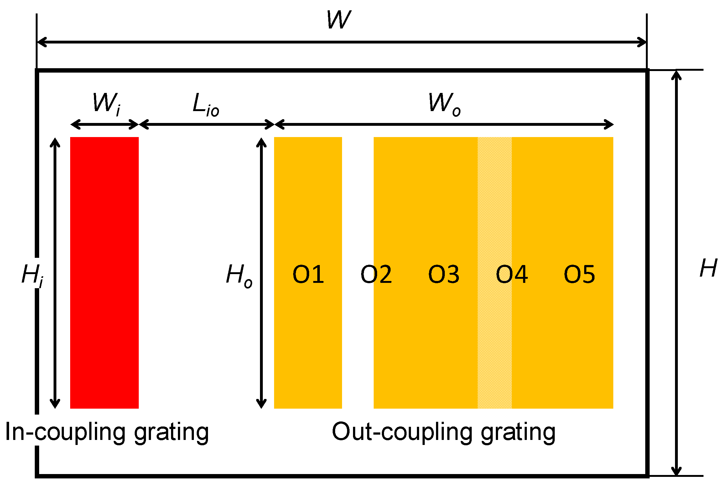
2.1. Dual-Channel Waveguide

Figure 1 schematically draws the cross-section of dual-channel waveguide, the top and bottom layers of which are referred to as channel 1 and channel 2, respectively. The left and right half-FOVs shall be of orthogonal polarizations, e.g., left-handed and right-handed circular polarizations. Gratings in channel 1―including the in-coupling and out-coupling―are responsive merely to the light coming from the left half of FOV. Gratings in channel 2, on the other hand, will take care of the rest of FOV, i.e., the right half. To evenly expand the pupil, the out-coupling grating consists of five sub-gratings―abbreviated as O1/O2/O3/O4/O5―with their efficiencies being modulated. For the sake of big FOV, RealView glass (Schott) [15] is chosen as the material of waveguide, whose refractive index nwg at 546 nm is 1.91048, yielding to a critical angle θc of 31.57°. For the light inside the waveguide to be reflected at angles greater than θc, gratings of channel 1 and channel 2 are tilted by θ1 and θ2, respectively. Other physical parameters regarding the waveguide and gratings, as shown in Figure 2, can be also found in Table 1, where W/H/D is the width/height/thickness of waveguide, Wi/o/Hi/o the width/height of in/out-coupling grating, and Lio the distance between the in-coupling and out-coupling gratings.

2.2. Number of Pupils

For a given field θwg―measured within the waveguide―its pupil will be duplicated by the number of TIRs NTIR, which can be determined from
N T I R = W o 2 D tan θ w g
As shown in Figure 3, when θwg < θc (31.57°), TIR does not occur. When θwgθc, the number of TIRs decreases all the way to 0. Say the number of duplicated pupils is supposed to be no less than 5. Then, the upper limit of field θmax will max out at 50°. Hence, 5 ≤ NTIR < 10 and 31.57° ≤ θwg ≤ 50°.

2.3. k-Domain

In an ideal scenario―when the waveguide can be infinitely large or curved or inhomogeneous, and minimally required number of TIRs or pupils is not considered―the theoretical boundary of k-domain solely depends on the refractive index of medium once the wavelength λ is given [11]. However, for a finite, flat, homogeneous waveguide, there shall exist a practical boundary of k-domain that will be defined by a circle with a radius Rmax
R m a x = 2 π n w g λ sin θ m a x
Suppose the input FOV is 80°, i.e., 72° (horizontal) × 45° (vertical), and the gratings of channel 1 and channel 2 could couple the light in and out such that:
sin 1 ( n a i r sin θ a i r n w g ) + θ 1 / 2 = θ w g θ 1 / 2
where nair is the refractive index of air, θair the field measured in air, and θwg the field measured in waveguide. When λ = 546 nm, nwg = 1.91048, θmax = 50° (for the minimal NTIR = 5), and θ1/2 = 16°/25°, k-domain can be plotted, as shown in Figure 4, in which green/blue rounded rectangle denotes the left/right-half FOV, innermost circle the theoretical boundary in air, and intermediate/outermost circle the practical/theoretical boundary in waveguide. It can be seen that, after splitting, two half-FOVs are located at the same side of k-domain, meaning that the EPE regions of two channels could be seamlessly overlapped.

2.4. Cholesteric Liquid Crystal Grating

In search of the gratings that would do the said jobs, we resort to the cholesteric liquid crystal (CLC) grating for several reasons. Number one, it is polarization-sensitive, i.e., only responsive to circularly polarized light of certain handedness [16]. Number two, it can be made achromatic by stacking or other multi-color techniques [17] so as to minimize the number of layers of waveguides. Since its reflection is per se a type of Bragg diffraction, the reflected wavelength λB and incident angle θi shall be correlated via
m λ B = p cos θ i ( n e 2 + 2 n o 2 ) / 3
where m is the diffraction order, p the helical or chiral pitch, and ne and no the extraordinary and ordinary refractive indices of liquid crystal, respectively. As Equation (4) indicates, CLC exhibits both wavelength and angular selectivity. In order for the gratings to be wide-band as well as wide-angle, a stack of CLCs satisfying different Bragg conditions are essential. Number three, CLC lends itself to waveguide couplers for its high efficiency and variable grating normal. The former can be guaranteed as long as the CLC is sufficiently thick to be a polarization volume grating. The latter is achieved by introducing a geometric or Pancharatnam–Berry (PB) phase through photoalignment [16] or holography [18] to CLC such that its grating normal can be tilted by the angle θ1/2 as [19]
sin θ 1 / 2 = p 2 Λ
where Λ is the PB pitch, also known as the alignment pitch. It is worth noting that Equation (5) is only valid for the slanted, thick CLC configuration. As for other possible CLC configurations, the calculation of grating normal will be subject to change [20].

3. Results and Discussion

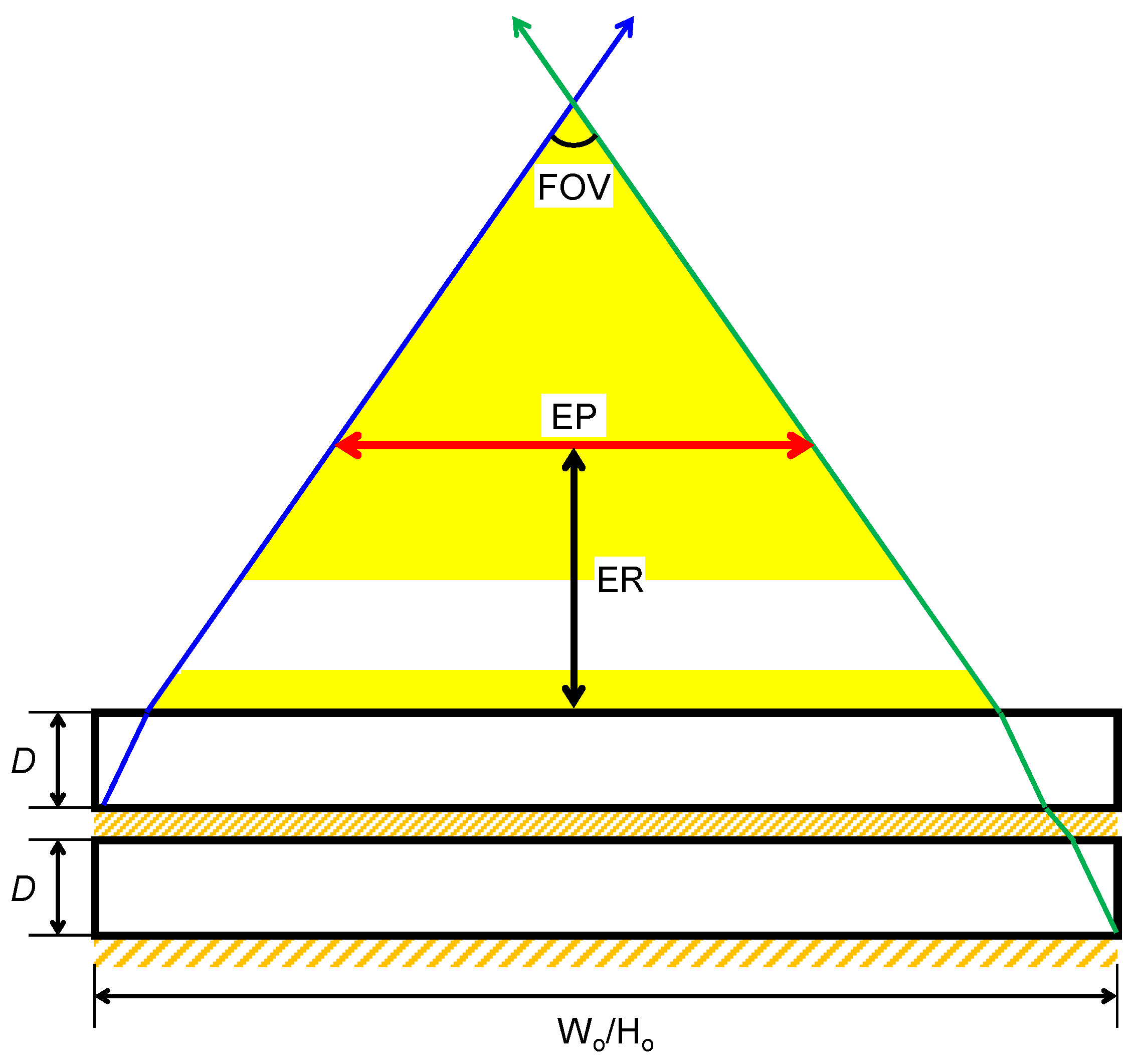
3.1. Field of View, Eye Relief and Exit Pupil

Figure 5 shows the geometric relationship among the FOV, eye relief (ER) and exit pupil (EP). With both the grating and optical adhesive sandwiched in between being ignored and applying the trigonometry together with Snell’s law, this relationship could be formulated as [11]
EP = W o / H o 3 · D · tan ( sin 1 ( n a i r sin ( FOV 2 ) n w g ) ) 2 · ER · tan ( FOV 2 )
from which one takeaway is that a big FOV tends to have a small exit pupil. For FOV = 72° (horizontal) × 45° (vertical) and ER = 10 mm, EP = 4 × 3 mm2. Incidentally, in addition to scaling up the waveguide or to shortening the eye relief [21], another solution is to make the waveguide movable to accommodate the variation of interpupillary distance.

3.2. Grating Efficiency

Table 2 lists the parameters for our tri-layer-stacked CLCs, whose Bragg wavelength, thickness, chiral pitch, and thickness-to-pitch ratio are specified. The calculation of stacked CLCs follows from the 4×4 matrix method [22]. As for the spectral bandwidth, the reflection efficiency or reflectance is computed with respect to the wavelength, as shown in Figure 6. The spectral bandwidth of reflectance from 45% to 50% for the red (R)/green (G)/blue (B) color is 47/40/34 nm, which is compatible with the light-emitting diodes as the light source. As for the angular bandwidth, reflectance is computed with respect to the incident angle―measured relative to the grating normal―as shown in Figure 7. The angular bandwidth of reflectance from 45% to 50% for R/G/B is 50/52/52 degrees, which is wide enough to cover half of the FOV.

3.3. Uniformity

With VirtualLab Fusion, the location of duplicated exit pupils can be obtained by tracing the rays of central field, as shown in Figure 8, where the entrance pupil is circular and 4 mm across. In order for the duplicated pupils to be uniform, by setting the uniformity error of the detector as the merit function and employing the Nelder–Mead or downhill simplex method, the normalized grating efficiencies of the reflected zeroth (R0) and first (R1) orders are tweaked as in Table 3. The uniformity, defined as
Uniformity = 2 I m i n I m a x + I m i n
where Imax and Imin are in turn the maximum and minimum intensities, can be analyzed by calculating the electromagnetic fields at the detector, as shown in Figure 9. The overlapped regions of pupils, where the light interferes with one another, are treated with coherent summation. As Imax = 0.2337 V2/m2 and Imin = 0.1510 V2/m2, the uniformity is 79%.

4. Conclusions

In conclusion, a wide-field-of-view NED with a dual-channel waveguide and design rules thereof have been studied. Instead of splitting the FOV by direction [11,12], our method is to split the FOV by polarization. The most important benefit is that the EPE regions of different channels could be overlapped. This could not only maximize the waveguide real estate or active area, but also improve the uniformity. In what follows, its key performance is recapitulated. FOV is 80° (diagonal), ER = 10 mm, EP = 4 × 3 mm2, and uniformity is 79%.

5. Patents

In light of the potential impact of this work, one invention patent (application number: 202111225152.8) was filed to China National Intellectual Property Administration on 21 October 2021.

Author Contributions

Conceptualization, C.P.C.; methodology, C.P.C.; software, Y.C.; validation, Y.C.; formal analysis, C.P.C.; investigation, Y.Y. and Y.L.; writing—original draft preparation, Y.Y., F.Y. and H.S.; writing—review and editing, C.P.C.; visualization, Y.C., Y.Y. and F.Y.; supervision, C.P.C.; project administration, G.L.; funding acquisition, G.L. All authors have read and agreed to the published version of the manuscript.

Funding

This research is funded by National Natural Science Foundation of China (61901264, 61831015), Science and Technology Commission of Shanghai Municipality (19ZR1427200), and Natural Science Foundation of Chongqing, China (cstc2021jcyj-msxmX1136).

Institutional Review Board Statement

Not applicable.

Informed Consent Statement

Not applicable.

Data Availability Statement

Data underlying the results presented in this paper are not publicly available but may be obtained from the authors upon reasonable request.

Acknowledgments

Special thanks to LightTrans International GmbH in Germany for offering the official license of VirtualLab Fusion.

Conflicts of Interest

The authors declare no conflict of interest.

References

  1. Chen, C.P.; Zhou, L.; Ge, J.; Wu, Y.; Mi, L.; Wu, Y.; Yu, B.; Li, Y. Design of retinal projection displays enabling vision correction. Opt. Express 2017, 25, 28223–28235. [Google Scholar] [CrossRef]
  2. Chen, C.; Li, H.; Zhang, Y.; Moon, C.; Kim, W.Y.; Jhun, C.G. Thin-film encapsulation for top-emitting organic light-emitting diode with inverted structure. Chin. Opt. Lett. 2014, 12, 022301. [Google Scholar] [CrossRef]
  3. Chen, C.P.; Wu, Y.; Zhou, L.; Wang, K.; Zhang, Z.; Jhun, C.G. Crosstalk-free dual-view liquid crystal display using patterned E-type polarizer. Appl. Opt. 2017, 56, 380–384. [Google Scholar] [CrossRef] [PubMed] [Green Version]
  4. Amitai, Y. Extremely compact high-performance HMDs based on substrate-guided optical element. In SID Symposium Digest of Technical Papers; Society for Information Display: Seattle, WA, USA, 23–28 May 2004; pp. 310–313. [Google Scholar]
  5. Levola, T. Diffractive optics for virtual reality displays. J. Soc. Inf. Disp. 2006, 14, 467–475. [Google Scholar] [CrossRef]
  6. Mukawa, H.; Akutsu, K.; Matsumura, I.; Nakano, S.; Yoshida, T.; Kuwahara, M.; Aiki, K. A full-color eyewear display using planar waveguides with reflection volume holograms. J. Soc. Inf. Disp. 2009, 17, 185–193. [Google Scholar] [CrossRef]
  7. Wu, Y.; Chen, C.P.; Zhou, L.; Li, Y.; Yu, B.; Jin, H. Design of see-through near-eye display for presbyopia. Opt. Express 2017, 25, 8937–8949. [Google Scholar] [CrossRef] [PubMed]
  8. Shi, Z.; Chen, W.T.; Capasso, F. Wide field-of-view waveguide displays enabled by polarization-dependent metagratings. Proc. SPIE 2018, 10676, 1067615. [Google Scholar]
  9. Yoo, C.; Bang, K.; Chae, M.; Lee, B. Extended-viewing-angle waveguide near-eye display with a polarization-dependent steering combiner. Opt. Lett. 2020, 45, 2870–2873. [Google Scholar] [CrossRef]
  10. Zhang, W.; Chen, C.P.; Ding, H.; Mi, L.; Chen, J.; Liu, Y.; Zhu, C. See-through near-eye display with built-in prescription and two-dimensional exit pupil expansion. Appl. Sci. 2020, 10, 3901. [Google Scholar] [CrossRef]
  11. Chen, C.P.; Mi, L.; Zhang, W.; Ye, J.; Li, G. Waveguide-based near-eye display with dual-channel exit pupil expander. Displays 2021, 67, 101998. [Google Scholar] [CrossRef]
  12. Vallius, T.; Tervo, J. Waveguides with Extended Field of View. U.S. Patent 9,791,703 B1, 13 April 2016. [Google Scholar]
  13. Kress, B.C. Optical Architectures for Augmented-, Virtual-, and Mixed-Reality Headsets, 1st ed.; SPIE: Bellingham, WA, USA, 2020. [Google Scholar]
  14. Guttag, K. Hololens 2 Display Evaluation Part 3: Color Uniformity. Available online: https://kguttag.com/2020/07/10/hololens-display-evaluation-part-3-color-uniformity (accessed on 7 November 2021).
  15. Schott. SCHOTT RealView. Available online: https://www.schott.com/en-us/products/schott-realview-p1000268 (accessed on 6 December 2021).
  16. Nys, I.; Stebryte, M.; Ussembayev, Y.Y.; Beeckman, J.; Neyts, K. Tilted chiral liquid crystal gratings for efficient large-angle diffraction. Adv. Opt. Mater. 2019, 7, 1901364. [Google Scholar] [CrossRef]
  17. Ryabchun, A.; Bobrovsky, A. Cholesteric liquid crystal materials for tunable diffractive optics. Adv. Opt. Mater. 2018, 6, 1800335. [Google Scholar] [CrossRef]
  18. Chen, C.P.; Su, Y.; Jhun, C.G. Recent advances in holographic recording media for dynamic holographic display. J. Opt. Photonics 2014, 1, 1–8. [Google Scholar] [CrossRef] [Green Version]
  19. Stebryte, M.; Nys, I.; Ussembayev, Y.Y.; Beeckman, J.; Neyts, K. Large angle forward diffraction by chiral liquid crystal gratings with inclined helical axis. Crystals 2020, 10, 807. [Google Scholar] [CrossRef]
  20. Yin, K.; Zhan, T.; Xiong, J.; He, Z.; Wu, S.-T. Polarization volume gratings for near-eye displays and novel photonic devices. Crystals 2020, 10, 561. [Google Scholar] [CrossRef]
  21. Mi, L.; Chen, C.P.; Lu, Y.; Zhang, W.; Chen, J.; Maitlo, N. Design of lensless retinal scanning display with diffractive optical element. Opt. Express 2019, 27, 20493–20507. [Google Scholar] [CrossRef] [PubMed]
  22. Yeh, P.; Gu, C. Optics of Liquid Crystal Displays, 2nd ed.; Wiley: Hoboken, NJ, USA, 2009. [Google Scholar]
Figure 1. Cross-section of dual-channel waveguide, the top and bottom layers of which are referred to as channel 1 and channel 2, respectively. The left and right half-FOVs shall be of orthogonal polarizations, e.g., left-handed and right-handed circular polarizations. Gratings in channel 1―including both the in-coupling and out-coupling―are responsive merely to the light coming from the left half of FOV. Gratings in channel 2, on the other hand, will take care of the rest of FOV, i.e., the right half.
Photonics 08 00557 g001
Figure 2. Plan view of dual-channel waveguide. To evenly expand the pupil, the out-coupling grating consists of five sub-gratings―abbreviated as O1/O2/O3/O4/O5―with their diffraction efficiencies being modulated. W/H/D is the width/height/thickness of waveguide, Wi/o/Hi/o the width/height of in/out-coupling grating, and Lio the distance between the in-coupling and out-coupling grating.
Photonics 08 00557 g002
Figure 3. Number of duplicated pupils with respect to the angle relative to the waveguide normal. When θwg < θc (31.57°), TIR does not occur. When θwgθc, the number of TIRs decreases all the way to 0. Say the number of duplicated pupils is supposed to be no less than 5. Then, the upper limit of field θmax will max out at 50°.
Photonics 08 00557 g003
Figure 4. Diagram of k-domain calculated when λ = 546 nm, nwg = 1.91048, and NTIR = 5. Green/blue rounded rectangle denotes the left/right-half FOV, innermost circle the theoretical boundary in air, and intermediate/outermost circle the practical/theoretical boundary in waveguide.
Photonics 08 00557 g004
Figure 5. Geometric relationship among the FOV, eye relief and exit pupil. For FOV = 72° (horizontal) × 45° (vertical) and ER = 10 mm, EP = 4 × 3 mm2.
Photonics 08 00557 g005
Figure 6. Reflectance with respect to the wavelength. The spectral bandwidth of reflectance from 45% to 50% for the R/G/B color is 47/40/34 nm, which is compatible with the light-emitting diodes as the light source.
Photonics 08 00557 g006
Figure 7. Reflectance with respect to the incident angle. The angular bandwidth of reflectance from 45% to 50% for R/G/B is 50/52/52 degrees, which is wide enough to cover half of the FOV.
Photonics 08 00557 g007
Figure 8. Location of duplicated exit pupils obtained by tracing the rays of central field. The entrance pupil is circular and 4 mm across.
Photonics 08 00557 g008
Figure 9. Uniformity analysis of duplicated exit pupils by calculating the electromagnetic fields at the detector. The overlapped regions of pupils, where the light interferes with one another, are treated with coherent summation.
Photonics 08 00557 g009
Table 1. Parameters of waveguide and gratings.
ObjectParameterValue
WaveguideW36 mm
H24 mm
D1.67 mm
nwg (633/546/486 nm)1.89781/1.91048/1.92411
θc (546 nm)31.57°
In-coupling gratingWi4 mm
Hi12 mm
θ1/2+16°/25°
Out-coupling gratingWo20 mm
Ho12 mm
Lio8 mm
θ1/2−16°/25°
Table 2. Parameters for stacked CLC gratings.
CLC LayerBragg WavelengthParameterValue
R633 nmd8 µm
p422.16 nm
d/p18.95
G546 nmd8 µm
p364.30 nm
d/p21.96
B486 nmd8 µm
p324.28 nm
d/p24.67
Table 3. Normalized efficiencies of gratings.
GratingEfficiency of R0 (%)Efficiency of R1 (%)
In-coupling1000
O189.68710.313
O290.2609.740
O389.52110.479
O488.28511.715
O572.73527.265
Publisher’s Note: MDPI stays neutral with regard to jurisdictional claims in published maps and institutional affiliations.

