Communication

Glycerol–Water Solution-Assisted Mach–Zehnder Temperature Sensor in Specialty Fiber with Two Cores and One Channel

1
Research Center for Advanced Optics and Photoelectronics, Department of Physics, College of Science, Shantou University, Shantou 515063, China
2
Key Laboratory of Intelligent Manufacturing Technology of MOE, Shantou University, Shantou 515063, China
3
Yangtze Optical Electronics Co., Ltd., East Lake Hi-Tech Developzone, Wuhan 430205, China
*
Author to whom correspondence should be addressed.
The first two authors contributed equally to this paper.
Photonics 2021, 8(4), 103; https://doi.org/10.3390/photonics8040103
Submission received: 16 March 2021 / Revised: 31 March 2021 / Accepted: 1 April 2021 / Published: 2 April 2021

Abstract

:
In this paper, we propose an in-fiber Mach–Zehnder temperature sensor based on a dual-core fiber with an eccentric core and a central core. The latter one is beside a fluidic channel embedded in the fiber. The effective refractive index of the guided mode in the central core could be influenced by the glycerol–water solution filled in the fluidic channel. Thus, the transmitted spectrum of the sensor is shifted as a function of temperature. By monitoring the selected spectral dip shifts, an experimental sensitivity of 2.77 nm/°C is obtained in the range of 25 to 40 °C for a solution length of 15 cm. To further improve the temperature sensitivity, the solution length is increased up to 29.5 cm, and a higher sensitivity of 5.69 nm/°C is achieved in the same temperature range. The experimental results agree well with the theoretical ones. The proposed sensor has good robustness and stability, which makes it promising for applications of high precision temperature monitoring.

1. Introduction

Optical fibers sensors (OFSs) have been extensively investigated and utilized for decades due to numerous advantages, such as high sensitivity, high compactness, corrosion resistance, anti-electromagnetic interference and remote monitoring. Based on these advantages, OFSs are popular for temperature, strain, refractive index, curvature and humidity measurements. In this paper, we focus on temperature sensing using OFSs, which have been realized by different types of structures and mechanisms, such as fiber Bragg gratings (FBGs) [1,2,3,4], long period gratings (LPGs) [5,6,7,8], Fabry–Perot (F-P) fiber interferometers [9,10,11,12] and Mach–Zehnder (M-Z) fiber interferometers [13,14,15,16], in the last 20 years. Fiber grating-based sensors normally operate by recording the variations of the resonance wavelength, which corresponds to thermally induced grating pitch and refractive index changes. Thus, grating-based OFSs normally have lower temperature sensitivities because of the relatively low thermo-optic coefficient and thermal expansion coefficient of the fiber material of silica. For example, Dong et al. produced an FBG in a D-shaped fiber with a temperature sensitivity of 28.7 pm/°C [1]. Hu et al. achieved a higher temperature of ~50 pm/°C by using poly(methyl methacrylate) (PMMA)-based polymer FBGs [4]. Han et al. obtained different temperature sensitivities of 130 pm/°C and 115 pm/°C based on LPGs in a standard single-mode fiber and in a single-mode double-clad fiber, respectively [5]. Theodosiou et al. first inscribed LPGs in a multi-mode cyclic transparent optical polymer (CYTOP) fiber using a femtosecond laser. The temperature sensitivity was found to be 704 pm/°C in the temperature range 42–67 °C [6]. Shu et al. reported a simple fabrication of LPGs in the conventional B-Ge co-doped fiber with a high sensitivity of 2.75 nm/°C [7]. Colaço et al. produced an arc-induced LPG in the B-Ge co-doped fiber in the dispersion turning point. The highest refractive index sensitivity obtained was −720 nm/RIU in the 1.33–1.41 refractive index range. This technique may potentially be applied for temperature measurement [8]. We note that grating-based sensors usually had relatively low sensitivities, which were typically smaller than 1 nm/°C. Thus, these sensors are not quite suitable for high-precision temperature measurements.
Compared to fiber grating-based sensors, interferometric OFSs normally operate with fiber refractive index modulations as a function of temperature variations, consequently shifting the resonant wavelengths in transmitted spectra. For example, Wang et al. proposed a high temperature sensor based on an F-P fiber interferometer. A sapphire wafer served as an F-P cavity fixed at the end face of the sapphire fiber encapsulated in a sleeve to improve structural stability. It had a large temperature measurement range of 25–1550 °C with a sensitivity of 32.5 pm/°C at 1550 °C [9]. Li et al. proposed an F-P fiber interferometer composed of a microfiber, a single-mode fiber, a silica glass capillary, and polydimethylsiloxane (PDMS) sol. The experimental sensitivity reached up to 6.386 nm/°C in the range 42 to 54 °C [10]. Though high temperature sensitivity was obtained, fabrication of this sensor required a tricky cleaving process at the microfiber end and complicated integration procedures.
For M-Z fiber interferometers, the propagating light in the fiber is normally separated into two or more routes or coupled to different modes, and afterward the separated light from different routes or modes recombines to generate interferometric amplitude spectra, which shift as a function of temperature. Geng et al. fabricated an M-Z fiber interferometer consisting of two concatenated waist-enlarged fusion bitapers, which were fabricated simply by fiber cleaving and fusion splicing. The sensitivity was 0.070 nm/°C [13]. Also based on the taper method, Wang et al. sandwiched a thin core fiber between two single mode fibers to develop an M-Z fiber interferometer with a temperature sensitivity of 0.065 nm/°C. To improve the temperature sensitivity, Gao et al. reported a single-mode-capillary-single-mode prototype using the core offset splicing technique. After filling the refractive index matching liquid with a large thermo-optic coefficient, the sensitivity was improved to 21.2 nm/°C [14]. However, the mechanical strength of this sensor is quite low due to a small fusion splice area. Zhao et al. presented a single-mode-multi-core-single-mode structure M-Z fiber interferometer by simply using a fiber splicing technique. The temperature sensitivity was 0.131 nm/°C [15]. In addition, Ma et al. proposed a high-performance temperature sensor based on the mode-coupling principle using a selectively filled solid-core photonic crystal fiber with a central air-bore. A high sensitivity of −6.02 nm/°C was obtained with a resolution of 3.32 × 10⁻³ °C in the range from −80 to 90 °C [16].
In this paper, combining both advantages of the refractive index matching liquid and the multi-core fiber, we propose an M-Z fiber interferometer based on a dual-core fiber (DCF), in which one core is in the center of the fiber, while the other eccentric one locates between the central core and the cladding surface. Additionally, a fluidic channel is embedded in the fiber right beside the central core but far from the other core. Based on this structure, liquid analytes could infiltrate the fluidic channel along the entire fiber for different parameter sensing applications, such as refractive index, magnetic field and temperature. Their sensitivity could be enhanced simply by increasing the effective fiber length. Here, we propose to use this DCF as a sensing platform to record variations in environmental temperatures in real-time. A non-toxic glycerol–water solution with high thermo-optic coefficients is filled in the fluidic channel with different lengths. The concentration of the solution is optimized to be close to the fiber core to improve the temperature sensitivity. Because of the large distance between the two cores, two single-mode fiber (SMF) pigtails are fusion spliced to the DCF via multi-mode fibers (MMFs), so that the guided modes in the dual cores can be excited, and then the guided light could recombine in the outlet single-mode fiber. Afterward, temperature modulations change the refractive index of the glycerol–water solution in the channel, consequently varying the effective refractive index of the guided mode in the central core. Thus, the transmitted spectra with resonances generated by interference shift as a function of the surrounding temperature. Spectral simulations with resonances versus temperatures are carried out using the Finite Element Method (FEM) method. Based on different fiber lengths (shorter fiber length: 20 cm with a solution length of 15 cm in the channel, longer fiber length: 36.5 cm with a solution length of 29.5 cm in the channel), the temperature measurements are characterized in the same range of 25–40 °C. For the shorter fiber, a linear fitting of spectral shift with respect to temperature suggests a sensitivity of 2.77 nm/°C, while for the longer counterpart, a sensitivity of 5.69 nm/°C is obtained. Both the experimental and simulation results in both sensors coincide well. The robustness sensor presented in this work can be fabricated easily without fiber tapering or a laser micromachining technique. The temperate sensitivity is fiber length dependent, and thus sensitivity can be further improved by filling more glycerol–water solution in the fiber channel. Moreover, the whole fiber sensor device can be coiled with high compactness.

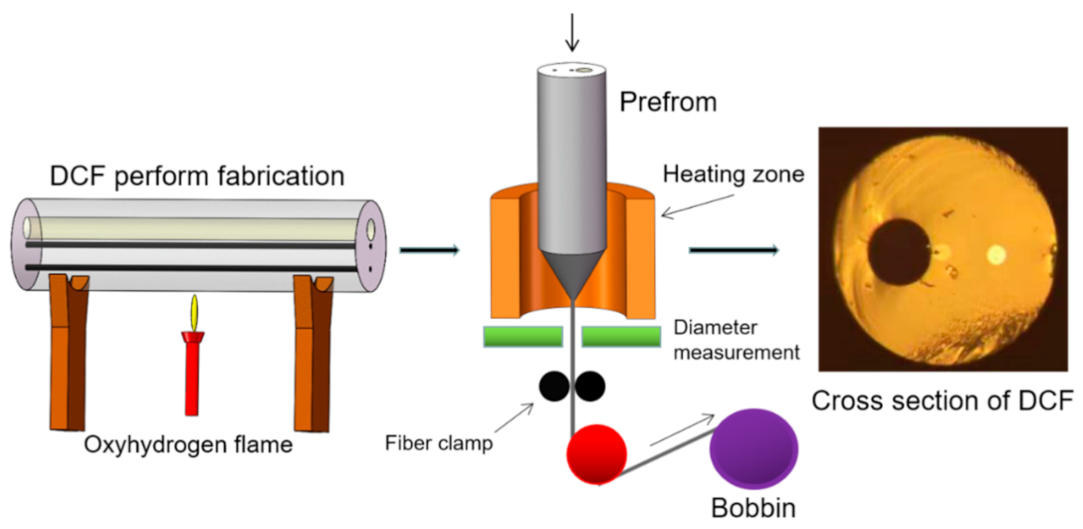
2. Fabrication of DCF

Firstly, a high-purity silica glass rod (HPSGR) with a diameter of 50 mm was needed, and then two holes ~3.1 mm in diameter were drilled in the middle and 1 / 4 diameter positions of this HPSGR. Secondly, two core rods with a diameter of 3 mm obtained by doping germanium in silica were inserted into the two drilled holes, and then they were fused together by a collapse process with oxyhydrogen flame. Thirdly, a hole 12 mm in diameter was drilled on the other side of the central hole, so that the hole and the two cores were in the same line, and the edge distance between the hole and the central core is 1 mm. Finally, the DCF with a cladding diameter of ~125 μm was drawn by a commercial fiber drawing tower at Yangtze Optical Electronics, Co. Ltd. The schematic of the fiber manufacturing process is shown in Figure 1. The diameters of the central core, the eccentric core and the hole are ~8.1, ~9.2, and ~36 μm, respectively. The center-to-center distance between the central core and the eccentric core is 30 μm, and the edge distance between the central core and the hole is 1.15 μm.

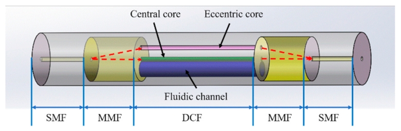
3. Operation Principle of the Sensor

The mechanism of the M-Z fiber interferometer sensor based on a DCF can be explained as follows. When the coherent laser beam is coupled to the two cores, guided modes in both cores are excited and propagate independently. Then, light from two cores is recombined in the single-mode fiber to generate interference transmitted spectra. Temperature-induced variations in the effective refractive index of the center-core modes change the phase difference among the modes guided by the two cores. The output spectral intensity of the transmitted light I o u t p u t can be expressed as:
I o u t p u t = I c c + I e c + 2 I c c I e c cos Δ φ ,
where I c c and I e c represent the intensities of the transmitted beams from the center core and the eccentric one, respectively, and φ represents the phase difference between the two propagating beams in both cores, and is expressed as:
Δ φ = 2 π L a i r Δ n a i r e f f + L s o l u t i o n Δ n s o l u t i o n e f f λ ,
where λ is the operating wavelength in vacuum, and L a i r and L s o l u t i o n are the length of the DCF channel filled with air and glycerol–water solution, respectively. Δ n a i r e f f = n a i r , c c e f f n a i r , e c e f f represents the effective refractive index difference between modes propagating in the center core and in the eccentric core for the DCF section without glycerol–water solution filled in the channel, while Δ n s o l u t i o n e f f = n s o l u t i o n , c c e f f n s o l u t i o n , e c e f f is the counterpart for the DCF section filled with glycerol–water solution. On the basis of Equations (1) and (2), the transmitted spectra of the sensor denote periodical intensity modulations, and the central wavelength λ m of the m-order interference dip can be defined as:
λ m = 2 ( L a i r Δ n a i r e f f + L s o l u t i o n Δ n s o l u t i o n e f f ) 2 m + 1 ,
where m is an integer. The central wavelength is a function of effective refractive index and fiber lengths with and without glycerol–water solution. The latter is influenced by surrounding temperatures. The thermo-optic coefficients of water and pure glycerol are −1.5 × 10⁻⁴/°C and −2.3 × 10⁻⁴/°C, respectively [17], with an estimated average value of −2.2 × 10⁻⁴/°C according to the composition of glycerol–water solution (glycerol mass fraction 85.9%, refractive index 1.45 @ 589 nm) used in this work. However, the counterparts of silica and air are 9.2 × 10⁻⁶/°C [18] and −9.8 ×10⁻⁷/°C [19], respectively, which are much smaller. Thus, temperature-induced refractive index changes for Δ n a i r , c c e f f Δ n a i r , e c e f f and Δ n s o l u t i o n , e c e f f can be omitted, and when surrounding temperature changes, the refractive index of the glycerol–water solution varies, which dominantly affects the effective refractive index Δ n s o l u t i o n , c c e f f of the modes propagating in the central core beside the solution because the guided mode in the core has partial modal overlap with the solution. Oppositely, the effective indices of the modes in the eccentric core and in the central core without the surrounding solution cannot be influenced due to a non-existent of modal overlap. As a result, temperature variations induce an effective refractive index change for the central core beside the solution Δ n s o l u t i o n , c c e f f and further result in the shifts of the spectral dips, which is the main mechanism for this presented M-Z fiber interference sensor. According to Equation (3), the temperature sensitivity can be deduced as follows:
S = d λ m d T 2 L s o l u t i o n 2 m + 1 · d Δ n s o l u t i o n e f f d T 2 L s o l u t i o n 2 m + 1 · d n s o l u t i o n , c c e f f d T .
According to the classic perturbation theory [20], changes of effective refractive index of the guided mode in the central core are related to surrounding temperature variations, expressed as:
δ n s o l u t i o n , c c e f f f · δ n s o l u t i o n = f · α · δ T ,
where   α is the thermo-optic coefficient of the glycerol–water solution; f is power overlap factor of the central core modes in the solution, which is expressed as:
f = s o l u t i o n R e ( E x H y * E y H x * ) d x d y t o t a l R e ( E x H y * E y H x * ) d x d y ,
where E x / y and H x / y refer to the electric and magnetic field in two orthodox directions in the fiber cross-sectional plane. According to Equations (4)–(6), the sensitivity of this sensor can be enhanced by increasing the length of the liquid filled in the fiber channel and the thermo-optic coefficient of the solution and reducing the refractive index difference between the solution and the central core in order to enhance the factor f . Therefore, we choose the glycerol–water solution as a thermally sensitive liquid filled in the fiber channel mainly for two reasons. First, it has a relatively high thermo-optic coefficient. Second, it has a measured refractive index of 1.45, which is close to yet somehow smaller than that of the fiber core, which ensures a high f factor. According to Equation (3), the free spectrum range (FSR) can be defined as:
F S R = λ m + 1 λ m λ m 2 ( L a i r Δ n a i r e f f + L s o l u t i o n Δ n s o l u t i o n e f f ) .

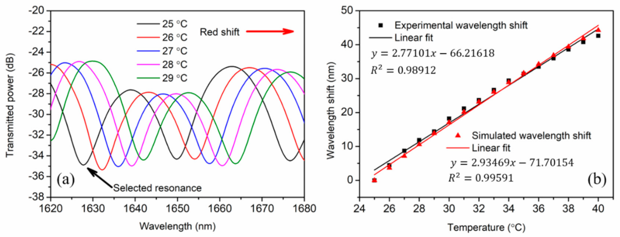
4. Experimental and Numerical Results

To fabricate this temperature sensor, an SMF pigtail with a core and cladding diameter of 8.2 and 125 mm, respectively, was first spliced with a short piece of MMF, which has a core and cladding diameter of 105 and 125 mm, respectively, using a fusion splicer (FSM-100M, Fujikura). Meanwhile, the prepared glycerol–water solution was infiltrated into the fluidic channel of the DCF by capillary effect. The effective sensing length of the DCF corresponds to the length of the glycerol–water solution in the fiber channel, which was confirmed by observing the solution–air interface in the fluidic channel using an optical microscope, as was shown in Figure 2a. Then, the end of the DCF filled with the solution was hung vertically so that the solution was moved to the center of the DCF along the fiber channel by gravity to avoid any negative influence on the DCF–MMF connectorization in the following fusion splice process. Due to the existence of the MMF with an optimized length of ~1 cm between the SMF and the DCF, the SMF–MMF–DCF structure enables the light to be coupled into the dual cores. In order to verify the propagating modes in the cores, a supercontinuum light source in the range 480–2200 nm (YSL Photonics, SC-5-FC) was launched to the SMF pigtail of the SMF–MMF–DCF structure, and then the output end-face of the DCF was visualized by using a 20 × objective and an infrared camera (Ghopto, GH-SWU2), as shown in Figure 2b. We found that LP01 modes were excited and thus propagated in the central core and in the eccentric core, respectively. After the mode verification, the other end of the DCF was fusion spliced to another MMF–SMF structure. Finally, the whole sensor structure SMF–MMF–DCF–MMF–SMF was built (Figure 3) without any air gap in the middle of the liquid filled in the channel and then twined with a diameter of 3 cm to form a compact sensing device. An optical spectral analyzer (OSA) (Anritsu MS9740A) was used to record the spectrum evolution with respect to temperature. The temperature characterization in the range (25−40 °C) was conducted with an interval of 1 °C. The twined fiber was stuck to the surface of a temperature-controlled breadboard (Thorlabs, PTC1, 15−45 °C) tightly by tapes. The temperature stability of this temperature-controlled breadboard is 0.1 °C, and the temperature readout resolution is ± 0.001 °C.
For the shorter fiber, the transmitted spectrum of this sensor shows a red shift as the temperature increases. With the initial temperature of 25 °C, the spectral dip at ~1628 nm was selected and then traced for temperature measurement, as shown in Figure 4a. Besides the selected dip, the maximal extinction ratio of each spectrum and the FSR were measured to be ~9 dB and ~22 nm, respectively. The quasi-linear dip evolution versus temperature was shown in Figure 4b. The experimental sensitivity of the sensor was calculated to be 2.77 ± 0.08 nm/°C. The nonlinear effect showing lower temperature sensitivity at higher temperature is attributed to the decreasing f factor, as the refractive index difference between the liquid and the central core increases, when temperature rises. It is worth mentioning that a more economical broad-band source (BBS) at the C+L band can be used instead of the supercontinuum used in this work, if we follow spectral resonance dips within the C+L band.
We used Comsol 5.0 to numerically simulate the guided modes in the DCF. Considering material dispersion at the spectrum range, the refractive index of the Ge-doped cores was set as 1.4485 [21], while the index of silica cladding is 0.006 lower. The refractive index of the glycerol–water solution was set to 1.439 [22]. The effective refractive index of the LP01 mode, n s o l u t i o n , e c e f f in the eccentric core in the solution-filled DCF segment is ~1.4455 (Figure 2c), while the effective index of the LP01 mode, n s o l u t i o n , c c e f f , in the central core of the same segment is ~1.4450 (Figure 2d). The effective refractive index of the LP01 mode, n a i r , e c e f f , in the eccentric core in the air-filled DCF segment is ~1.4455, while the effective refractive index of the LP01 mode, n a i r , c c e f f , is ~1.4448 in the central core of the same segment. According to Equation (7), the FSR was calculated to be ~22 nm with, L a i r = 5   c m , L s o l u t i o n = 15   c m . The simulated result matches well with the experimental counterpart. Based on these parameters and Equation (3), the integer m was calculated to be −75 for the spectral dip at ~1632 nm. Furthermore, considering the thermo-optic coefficient of the glycerol–water solution (−2.2 × 10⁻⁴/°C) and silica (9.2 × 10⁻⁶/°C), we could simulate the effective refractive index of each mode with different temperatures, and then calculate the corresponding shifts of the selected spectral dip at ~1632 nm with the same m value of −75. The simulated spectral dip shift as a function of temperature and its linear fit is shown in Figure 4b with a temperature sensitivity of 2.93 ± 0.05 nm/°C. The spectral evolution and the sensitivity are similar to the experimental results.
To further improve the temperature sensitivity, the length of the DCF channel filled with the glycerol–water solution was increased to 29.5 cm with a total DCF length of 36.5 cm. The sensor structure is the same as that of the shorter one. The transmitted spectra of the sensor were measured in the temperature range of 25−40 °C with a temperature interval of 1 °C, as shown in Figure 5a.
The maximum extinction ratio of each spectrum was measured to be ~10 dB, and the FSR was ~15 nm. The transmitted spectrum of the sensor also shows a red shift as the temperature increases. By following the initial spectral dip shift at ~1634 nm, an experimental sensitivity of 5.69 ± 0.05 nm/°C was obtained, as shown in Figure 5b. By using the similar effective refractive indices ( n s o l u t i o n , e c e f f , n s o l u t i o n , c c e f f , n a i r , e c e f f , n a i r , c c e f f ) of the guided modes as the former ones, we calculated the FSR to be ~15 nm, which also coincides well with the experimental result. Moreover, the integer m = 113 for the selected spectral resonance at ~1638 nm was obtained. Then, the effective refractive index of the guided modes at different temperatures was calculated, and the calculated variations of the selected spectral dip at ~1638 nm with a linear fit were also shown in Figure 5b. The simulated temperature sensitivity was calculated to be 5.44 ± 0.09 nm/°C, also similar to the experimental result.

5. Conclusions

In conclusion, we proposed an in-fiber Mach–Zehnder temperature sensor with a structure of SMF–MMF–DCF–MMF–SMF. The sensor operating principle is based on the interference of the two propagating modes in the dual cores. The eccentric core serves as a reference arm, while the central core adjacent to the fluidic channel filled with glycerol–water solution works as a sensing arm. Thus, the interfered transmitted spectrum of the sensor shifts as a function of temperature. Both experiments and numerical simulations were carried out to characterize the temperature sensor. For the 20-cm-long DCF infiltrated with 15-cm-long glycerol–water solution, the experimental sensitivity of 2.77 nm/°C was obtained in the range of 25 to 40 °C. For the 36.5-cm-long DCF infiltrated with 29.5-cm-long solution, a higher sensitivity of 5.69 nm/°C was achieved in the range of 25 to 40 °C. The experimental results coincided well with the simulated counterparts. The proposed sensor has good robustness and stability. We believe that this sensing regime may be potentially used for high precision temperature measurements as well as detection of other parameters, such as liquid or gas refractive index or magnetic field, thanks to the presence of the fluidic channel.

Author Contributions

Conceptualization, X.H. and H.Q. (Hang Qu); methodology, H.Q. (Haiming Qiu) and C.Z.; investigation, H.Q. (Haiming Qiu), C.Z., H.C., and Q.Y.; writing—original draft preparation, H.Q. (Hang Qu) and X.H.; writing—review and editing, H.Q. (Hang Qu) and Z.L.; supervision, X.H. All authors have read and agreed to the published version of the manuscript.

Funding

This project is supported by the Specialized Project Fund in Science and Technology of Guangdong Province (no. 190827105565385 and 190827105545434), Special projects in key fields of colleges and universities in Guangdong Province (no. 2020ZDZX3035 and 2020ZDZX3037), the Start-up fund (no. NTF19023 and NTF18016) from Shantou University, and the Optics and Photoelectronics Project (no. 2018KCXTD011).

Institutional Review Board Statement

Not applicable.

Informed Consent Statement

Not applicable.

Data Availability Statement

Data sharing is not applicable.

Conflicts of Interest

The authors declare that they have no known competing financial interests or personal relationships that could have appeared to influence the work reported in this paper.

References

  1. Dong, Y.; Xiao, S.; Wu, B.; Xiao, H.; Jian, S. Refractive index and temperature sensor based on D-Shaped fiber combined with a fiber Bragg grating. IEEE Sens. J. 2019, 19, 1362–1367. [Google Scholar] [CrossRef]
  2. Hirayama, N.; Sano, Y. Fiber Bragg grating temperature sensor for practical use. ISA Trans. 2000, 39, 169–173. [Google Scholar] [CrossRef]
  3. Zhang, B.; Kahrizi, M. High-temperature resistance fiber Bragg grating temperature sensor fabrication. IEEE Sens. J. 2007, 7, 586–591. [Google Scholar] [CrossRef]
  4. Hu, X.; Pun, C.F.J.; Tam, H.Y.; Mégret, P.; Caucheteur, C. Highly reflective Bragg gratings in slightly etched step-index polymer optical fiber. Opt. Express 2014, 22, 18807–18817. [Google Scholar] [CrossRef]
  5. Qu, H.; Lan, X.; Huang, J.; Kaur, A.; Wei, T.; Gao, Z.; Xiao, H. Long-period grating inscribed on concatenated double-clad and single-clad fiber for simultaneous measurement of temperature and refractive index. IEEE Photon. Technol. Lett. 2012, 24, 1130–1132. [Google Scholar]
  6. Theodosiou, A.; Min, R.; Leal-Junior, A.; Ioannou, A.; Frizera, A.; Pontes, M.; Marques, C.; Kalli, K. Long period grating in a multimode cyclic transparent optical polymer fiber inscribed using a femtosecond laser. Opt. Lett. 2019, 44, 5346–5349. [Google Scholar] [CrossRef]
  7. Shu, X.; Allsop, T.; Gwandu, B.; Zhang, L.; Bennion, I. High-temperature sensitivity of long-period gratings in B-Ge codoped fiber. IEEE Photon. Technol. Lett. 2001, 13, 818–820. [Google Scholar]
  8. Colaço, C.; Caldas, P.; Villar, I.D.; Chibante, R.; Rego, G. Arc-induced long-period fiber gratings in the dispersion turning points. J. Light. Technol. 2016, 34, 4584–4590. [Google Scholar] [CrossRef]
  9. Wang, B.; Niu, Y.; Zheng, S.; Yin, Y.; Ding, M. A High temperature sensor based on sapphire fiber Fabry-Perot interferometer. IEEE Photonics Technol. Lett. 2020, 32, 89–92. [Google Scholar] [CrossRef]
  10. Li, J.; Li, Z.; Yang, J.; Zhang, Y.; Ren, C. Microfiber Fabry-Perot interferometer used as a temperature sensor and an optical modulator. Opt. Laser. Technol. 2020, 129, 106296. [Google Scholar] [CrossRef]
  11. Zhao, L.; Zhang, Y.; Chen, Y.; Wang, J. Composite cavity fiber tip Fabry-Perot interferometer for high temperature sensing. Opt. Fiber Technol. 2019, 50, 31–35. [Google Scholar] [CrossRef]
  12. Domínguez-Flores, C.E.; Monzón-Hernández, D.; Moreno-Basulto, J.I.; Rodríguez-Quiroz, O.; Minkovich, V.P.; López-Cortés, D.; Hernández-Romano, I. Real-time temperature sensor based on in-fiber Fabry–Perot interferometer embedded in a resin. J. Light. Technol. 2019, 37, 1084–1090. [Google Scholar] [CrossRef]
  13. Geng, Y.; Li, X.; Tan, X.; Deng, Y.; Yu, Y. High-sensitivity Mach–Zehnder interferometric temperature fiber sensor based on a waist-enlarged fusion bitaper. IEEE Sens. J. 2011, 11, 2891–2894. [Google Scholar] [CrossRef]
  14. Gao, S.; Ji, C.; Ning, Q.; Chen, W.; Li, J. High-sensitive Mach-Zehnder interferometric temperature fiber-optic sensor based on core-offset splicing technique. Opt. Fiber Technol. 2020, 56, 102202. [Google Scholar] [CrossRef]
  15. Zhao, Z.; Tang, M.; Fu, S.; Liu, S.; Wei, H.; Cheng, Y.; Tong, W.; Shum, P.P.; Liu, D. All-solid multi-core fiber-based multipath Mach–Zehnder interferometer for temperature sensing. Appl. Phys. B 2013, 112, 491–497. [Google Scholar] [CrossRef]
  16. Ma, J.; Yu, H.H.; Jiang, X.; Jiang, D.S. High-performance temperature sensing using a selectively filled solid-core photonic crystal fiber with a central air-bore. Opt. Express 2017, 25, 9406–9415. [Google Scholar] [CrossRef]
  17. Cao, Z.; Jiang, L.; Wang, S.; Wang, M.; Liu, D.; Wang, P.; Zhang, F.; Lu, Y. All-glass extrinsic Fabry–Perot interferometer thermo-optic coefficient sensor based on a capillary bridged two fiber ends. Appl. Opt. 2015, 54, 2371–2375. [Google Scholar] [CrossRef]
  18. Chang, S.; Hsu, C.C.; Huang, T.H.; Chuang, W.C.; Tsai, Y.S.; Shieh, J.Y.; Leung, C.Y. Heterodyne interferometric measurement of the thermo-optic coefficient of single mode fiber. Chin. J. Phys. 2000, 38, 437–442. [Google Scholar]
  19. Bauld, R.; Choi, D.Y.W.; Bazylewski, P.; Divigalpitiya, R.; Fanchini, G. Thermo-optical characterization and thermal properties of graphene–polymer composites: A review. J. Mater. Chem. C 2017, 6, 2901–2904. [Google Scholar] [CrossRef]
  20. Qu, H.; Skorobogatiy, M. Resonant bio- and chemical sensors using low-refractive-index-contrast liquid-core Bragg fibers. Sens. Actuators B Chem. 2012, 161, 261–268. [Google Scholar] [CrossRef]
  21. Rodney, W.S.; Spindler, R.J. Index of refraction of fused quartz glass for ultraviolet, visible, and infrared wavelengths. J. Opt. Soc. Am. 1954, 44, 677–679. [Google Scholar] [CrossRef]
  22. Rheims, J.; Köser, J.; Wriedt, T. Refractive-index measurements in the near-IR using an Abbe refractometer. Meas. Sci. Technol. 1997, 8, 601–605. [Google Scholar] [CrossRef]
Figure 1. Schematic of the fabrication process of the dual-core fiber (DCF).
Photonics 08 00103 g001
Figure 2. (a) Interface between the glycerol–water solution and the air in the channel of the DCF; (b) Guided modes of DCF experimentally visualized by an infrared camera; (c) LP01 mode simulation in the eccentric core in the solution-filled DCF; (d) LP01 mode simulation in the central core in the solution-filled DCF.
Photonics 08 00103 g002
Figure 3. Schematic illustration of the SMF–MMF–DCF–MMF–SMF structure of the temperature sensor. SMF—single-mode fiber, MMF—multi-mode fiber.
Photonics 08 00103 g003
Figure 4. (a) Partial transmitted spectrum evolution of the sensor measured in the temperature range of 25 to 29 °C. The length of the infiltrated glycerol–water solution is 15 cm; (b) experimental and simulated wavelength shift of the spectral dip at ~1628 nm as a function of temperature in the range of 25 to 40 °C.
Photonics 08 00103 g004
Figure 5. (a) Partial transmitted spectrum evolution of the sensor measured in the temperature range of 25 to 29 °C. The length of the infiltrated glycerol–water solution is 29.5 cm; (b) experimental and simulated wavelength shift of the spectral dip at ~1634 nm as a function of temperature in the range of 25 to 40 °C.
Photonics 08 00103 g005
Publisher’s Note: MDPI stays neutral with regard to jurisdictional claims in published maps and institutional affiliations.

