Article

Keen Investigation of the Electromagnetic Scattering Characteristics of Tiltrotor Aircraft Based on Dynamic Calculation Method

1
School of Aeronautic Science and Engineering, Beihang University, Beijing 100191, China
2
HIWING Aviation General Equipment Corporation Limited, Beijing 100074, China
3
AVIC SAC Commercial Aircraft Company Limited, Shenyang 110179, China
*
Author to whom correspondence should be addressed.
Photonics 2021, 8(6), 175; https://doi.org/10.3390/photonics8060175
Submission received: 15 April 2021 / Revised: 4 May 2021 / Accepted: 20 May 2021 / Published: 21 May 2021
(This article belongs to the Section Optical Communication and Network)

Abstract

:
To study the radar characteristics of the tiltrotor aircraft when considering rotor rotation and tilting actions, a dynamic calculation method (DCM) based on physical optics and physical theory of diffraction is presented. The results show that the radar cross section of a single rotor is dynamic and periodic when it rotates, while increasing the rotation speed can shorten this period. At a fixed tilt angle, the overall radar cross section of the cabin plus rotor still exhibits various dynamic characteristics at different azimuths when considering the rotation of the rotor. Increasing the tilt angle can better improve the electromagnetic scattering level of the rotor, but this easily makes the cabin and the outer end of the wing become a new source of strong scattering. In the heading direction, the dynamic radar cross section of the aircraft under a larger azimuth angle is lower when the cabin tilts from horizontal to vertical position. The presented DCM is feasible and effective to obtain the electromagnetic scattering characteristics of tiltrotor aircraft.

1. Introduction

With the various functions of vertical take-off and landing, high-speed cruise and hovering in the air, the tilt-rotor has become the favored object of reconnaissance/transportation aircrafts. However, radar detection equipment on various platforms in the future battlefield will continue to develop and be used jointly, which brings new challenges to the stealth and survivability of tiltrotor aircraft [1,2,3].
Electromagnetic modeling technology is widely used in the evaluation of radar characteristics of aircraft, helicopters and aerial animals [4,5,6]. The radio wave scattering model of a bat is established and method of moment (MOM) is used to calculate the radar cross section (RCS) of this organic creature. The panel RCS of the helicopter rotor is determined by the physical optics (PO) and the scattering characteristics of the split edge are calculated by the equivalent currents method, where the quasi-static principle (QSP) is adopted to simulate the rotary motion of the rotor [7]. Unlike the radar signature of fixed-wing aircraft and birds, the aerodynamic and electromagnetic scattering characteristics brought by tilting rotors are more complex [8,9,10]. Changes in incident wave frequency, rotor rotation speed and attitude angle will all affect the dynamic RCS of conventional helicopters [11,12,13]. It is worth noting that the tilt rotor aircraft can adjust the rotor shaft from the horizontal position to the vertical position while keeping the posture of the fuselage unchanged [14]. Being much larger than the existence of a bird or flying insect, the tiltrotor has a much larger adjustment angle of the rotor disc than a conventional/coaxial helicopter, which will cause its RCS to have a large magnitude and fluctuation at more azimuths [15,16,17]. The multi-rotor dynamic scattering method is presented to evaluate the RCS of the compound helicopter, which guides the calculation of the radar characteristics of the tilt-rotor aircraft [18,19,20]. It can be seen that the radar stealth characteristics of fixed-wing aircraft and helicopters [21,22,23,24] and the aerodynamics and control strategies of tilt-rotor aircraft have received rich research results [25,26,27,28,29], while there is very little work and investigation in the stealth research of tiltrotor aircraft. The exploration of tilt-rotor RCS has academic significance and engineering value for the survivability and comprehensive combat effectiveness of this aircraft on the future battlefield.
Here, we present a dynamic calculation method (DCM) based on PO and PTD (physical theory of diffraction) to calculate the RCS of the tiltrotor aircraft. On this basis, we investigate the dynamic and periodic characteristics of the rotor RCS under different radar wave frequencies and observation angles. The dynamic RCS performance of the aircraft under the key azimuth at a fixed tilt angle is also worth exploring, which is related to what kind of deformation shape the aircraft should maintain when entering the battlefield. The effect of rotor tilting action on the stealth characteristics of aircraft radar needs to be studied, including dynamic electromagnetic scattering and changes in RCS peak/average.
In this manuscript, the method is presented in Section 2. Models are built in Section 3. The results are provided and discussed in detail in Section 4. Finally, the full article is summarized in Section 5.

2. Dynamic Calculation Method

The schematic diagram of the dynamic electromagnetic scattering of the tiltrotor aircraft is shown in Figure 1, where Ac1 represents the tilt angle of cabin 1, α represents the azimuth angle between the radar station and the aircraft, β represents the elevation angle between the radar station and the aircraft [29,30,31,32], Ar1 is the rotation angle of rotor 1. In fixed-wing mode, the rotation of the rotor and the tilt of the rotor cabin will change the radar stealth characteristics of the aircraft [33,34], especially in the heading direction.

2.1. Dynamic Scattering Calculation

When the cabin is in a horizontal position, the rotor axis is parallel to the x axis. In the current coordinate system, the motion of the rotor can be described as follows:
M y m r 1 t = 0 = M y m r 1 t = 0 Y r 1
M r 1 , x m r 1 t = 1 0 0 0 cos A r 1 t sin A r 1 t 0 sin A r 1 t cos A r 1 t × M y m r 1 t = 0
where mr1 represents the model of rotor 1, M(mr1) is the grid coordinate matrix of rotor 1, Yr1 is the distance from the axis of rotor 1 to the xz plane, t is time. Return the rotated model of rotor 1 to the outer end of the wing:
M r 1 , y m r 1 t = M r 1 , x y m r 1 t + Y r 1
Combine cabin 1 and rotor 1 to get the following model:
M r 1 c 1 m r 1 c 1 t = M r 1 , y m r 1 t , M c 1 m c 1 t = 0
where mc1 is the model of cabin 1, Mc1(mc1) is the grid coordinate matrix of cabin 1. When the rotor 1 tilts with the cabin 1, the process can be expressed as:
M r 1 c 1 , x m r 1 c 1 t = M r 1 c 1 x m r 1 c 1 t + X c 1
M r 1 c 1 , z x m r 1 c 1 t = M r 1 c 1 , x z m r 1 c 1 t Z c 1
M r 1 c 1 , y m r 1 c 1 t = cos A c 1 t 0 sin A c 1 t 0 1 0 sin A c 1 t 0 cos A c 1 t × M r 1 c 1 , z x m r 1 c 1 t
where Xc1 is the distance from the tilt axis of cabin 1 to the yz plane, Zc1 is the distance from the tilt axis of cabin 1 to the xy plane. Then, return cabin 1 and rotor 1 to the outer end of the wing, follow the above steps to simulate rotor 2 and cabin 2 and the dynamic model of the aircraft can be obtained as shown below:
M a m a t = M r 1 c 1 m r 1 c 1 t , M r 2 c 2 m r 2 c 2 t , M f m f t
where ma(t) is the dynamic model of the aircraft, mf is the model of fuselage, Ma(ma(t)) is the grid coordinate matrix of the dynamic model of the aircraft. If the posture of the fuselage has not changed:
M a m a t = M r 1 c 1 m r 1 c 1 t , M r 2 c 2 m r 2 c 2 t , M f m f t = 0
According to the physical optics method, under the irradiation of incident radar waves, the surface of this aircraft will induce surface electric current and surface magnetic current. The integral area of these electromagnetic currents can be extracted as:
S a t M a m a t
Then, the RCS determined by PO is:
σ PO t = j k π n ^ e ^ s × h ^ i S a t e j k w r d S
where σ is RCS, k is the wave number, n ^ is outer normal vector of the surface element, e ^ s is the direction vector of scattering electric field, h ^ i is the direction vector of the incident magnetic field, r’ is the position vector of the source point, dS is the integral face. Here, w can be expressed as:
w = s ^ i ^
where s ^ is the radiation direction vector, i ^ is the unit vector of incident wave. After transforming the integral term, the following form can be obtained:
σ PO t = j k π n e s × h i e j k w r 0 t I t
where r0 represents the coordinate vector of the reference point on the integral surface element, I(t) represents an integral expression, which can be obtained according to the following calculation when triangular facets are used:
I t = e j k w r m t j k p 2 m = 1 3 p L m sinc k w L m 2 , p 0 A f , p = 0
where Lm is the vector of the m-th edge on the facet, Af refers to the area of the integral facet, noting that p represents a defined vector cross product:
p = n × w
sinc x = sin x / x
The physical theory of diffraction (PTD) is used to solve the edge electromagnetic scattering of the aircraft, then the total RCS can be expressed as:
σ t = i = 1 N F ( t ) σ PO ( t ) i + j = 1 N E ( t ) σ PTD ( t ) j 2 , t 0 , T ob
where NF represents the number of facets, NE represents the number of edges, Tob is the observation time. For a single rotor, in order to capture the complete dynamic RCS in one cycle, Tob needs to satisfy the following relationship:
T ob t b , t b = A b ω r π 180 , A b = 360 N b
where tb is the basic passing time, Ab is the angle between two adjacent blades of the rotor, ωr is the angular velocity of the rotor, Nb is the number of blades of the rotor.
When considering the rotation of the cabin, Tob should satisfy:
T ob max N b t b , t c , t c = A ct ω c π 180
where tc is the tilting time of the cabin, Act is the final tilt angle of the cabin, ωc is the angular velocity of the cabin. For more information about dynamic scattering calculation methods, please refer to the literature [16,20]. For single or small sample calculations, PO + PTD is feasible and fast. When considering rotor + cabin, rotor + fuselage and multi-rotor dynamic scattering at the same time, PO + PTD or other conventional methods are difficult to describe the changes in aircraft RCS at a given observation angle, while emergence of DCM is to solve the electromagnetic scattering characteristics of the tilting rotor under given conditions.

2.2. Method Validation

The verification of DCM is shown in Figure 2, where GTD is geometric theory of diffraction. FEKO is FEldberechnung bei Korpern mit beliebiger Oberflache, which is a professional commercial electromagnetic simulation software, where PO + MOM (method of moment)/MLFMM (multi-level fast multipole method) is used to calculate the RCS of the target. QSP is quasi-static principle, used to discretize the rotation state of the rotor, so as to determine the dynamic RCS of the rotor in combination with conventional methods. For the RCS~α results as shown in Figure 2a, it can be seen that the three curves are generally similar except for differences in local fluctuations, where the average value of the RCS curve under DCM is 10.44 dBm2, that under FEKO is 10.74 dBm2, while the RCS mean of PO + GTD is smaller than these two values, because PTD can well eliminate the singularity of GTD and has a better ability to describe edge diffraction, the FEKO method here uses a hybrid algorithm and the solution to the rotor RCS at a certain moment is accurate.
In Figure 2b, it can be noticed that DCM can continuously and highly accurately reflect the changes of the RCS of the rotor, while the conventional method can only perform calculations in a few discrete states when dealing with a single rotor, which is inefficient and cumbersome. These results show that DCM is feasible and accurate to describe the dynamic radar cross section of the target.

3. Models

The model of the tiltrotor is established as shown in Figure 3, where the length of the aircraft fuselage Lf = 16.1 m, the height of the fuselage Hf = 3.51 m, the length of the wing Lw = 11.8 m, the inclination angle of the vertical tail Av = 42.92°, the distance between the tops of the vertical tails Wv = 4.87 m, the radius of rotor 2 Rr2 = 3.1 m, noting that the size of rotor 1 and rotor 2 are the same. The length of the rotor 2 hub Lh2 = 1.4 m, the diameter of the rotor 2 hub Dh2 = 0.8 m, the length of cabin 2 Lc2 = 3 m, the width of cabin 2 Wc2 = 1.15 m.
High-precision mesh generation technique is used to discretize the surface of the aircraft model to obtain the triangular surface metadata of the fuselage and its components as shown in Figure 4. For regions and details with small size or large curvature variation, mesh density enhancement technology is used to improve the bin of these regions, including hub edge, blade leading/trailing edge, tail, fuselage edge and wing leading/trailing edge. The size distribution of the surface grid of each part of the aircraft is shown in Table 1.

4. Results and Discussion

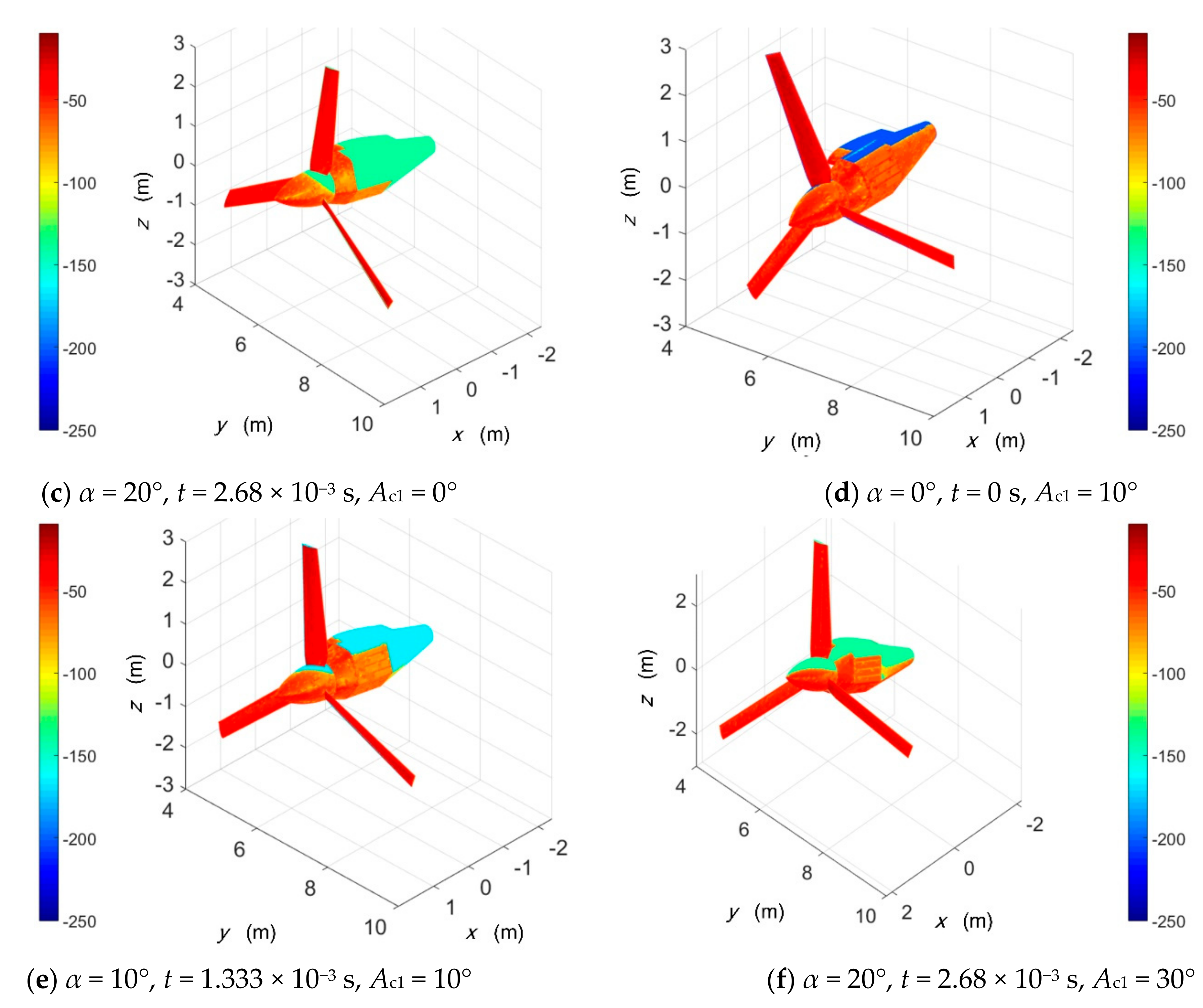
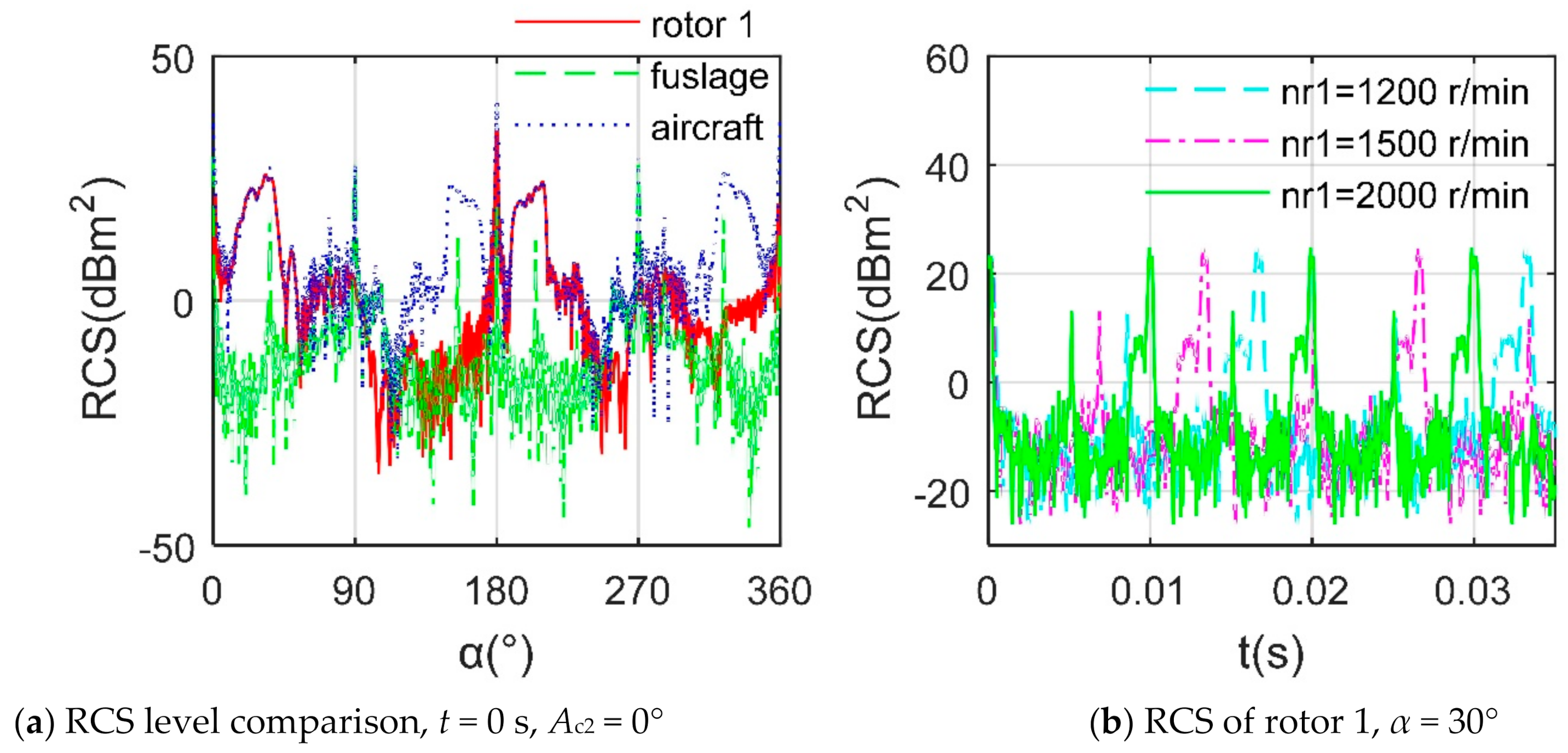
4.1. Analysis of Scattering Sources

The rotor blade is a curved surface formed by the gradual twisting, scaling and affine of the root airfoil to the tip, which makes its surface always have a local area that is not conducive to deflecting the incident radar wave when it rotates [35,36,37,38]. As shown in Figure 5a, most of the blade surface, the front area of the cabin and the head of the rotor hub show a darker red under the irradiation of 0° azimuth radar waves, which indicates that the bins on these areas have larger RCS values, where nr1 is the rotation speed of rotor 1, frh represents radar wave frequency and horizontal polarization. As the rotor rotates and the azimuth angle increases (Figure 5b,c), the performance of the strong scattering source on the blade is still obvious, the RCS on the hub gradually increases and a lot of orange and red appears on the side panel of the cabin. When the cabin is tilted 10° as shown in Figure 5d, the scattering sources on the surface of the propeller hub and the cabin have undergone more obvious changes compared with Figure 5a. With the further increase of the cabin inclination angle as shown in Figure 5e,f, the high RCS area on the hub and the side of cabin has been greatly improved, because the side of the cabin adopts a double inclination design, it is helpful for the upper part of the side of the cabin to deflect the incident radar wave to a non-threatening direction. On the whole, the red color of the blade in Figure 5f is lighter than that in Figure 5c, which is caused by the increase in the cabin inclination.

4.2. Influence of Different Components

It can be seen that the RCS curve of the rotor at 6 GHz and 16 GHz is generally similar to the RCS curve of the rotor at 10 GHz as shown in Figure 6a, where the maximum peaks of the three curves all appear at 180.3° azimuth. The peak value of the RCS curve at 6 GHz is 30.78 dBm2, that at 10 GHz is 34.72 dBm2 and that at 16 GHz is 37.93 dBm2, because the specular reflections of the hub and blades are very strong at this time and as the frequency of the radar wave increases, local areas with small dimensions are more likely to become relatively strong scattering sources, such as the trailing edge of the blade. In Figure 6b, as the frequency of the radar wave increases from 2 GHz to 16 GHz, the average RCS of the rotor under VV gradually increases from 13.81 dBm2 to 15.45 dBm2, while the influence of the polarization mode is significantly reduced.
Due to the initial stealth design, the fuselage has achieved better low RCS performance as shown in Figure 7a, where Ac2 represents the tilt angle of cabin 2, the electromagnetic scattering level of the entire aircraft is higher than that of the rotor and the fuselage, because it superimposes the RCS of the fuselage, two rotors and their cabins in phase. For the Figure 7b, the RCS of the rotor under different rotation speeds all show obvious dynamic and periodic characteristics and the increase of the rotation speed will shorten this period, because the three blades are evenly distributed, the faster rotation speed can make any one of the blades faster to complete the rotation of the angle between adjacent blades.
In Figure 8a, it can be observed that the RCS curves under α = 5° and 10° both show large fluctuations and their periods are both 1.33 × 10⁻² s, while the RCS curve under α = 0° is shown as a straight line compared with the other two RCS curves, in fact, its period is also equal to 1.33 × 10⁻² s, but the fluctuation is very small, because the rotor disk is perpendicular to the incident wave at this time, no matter how the rotor rotates, the RCS brought by the hub remains unchanged and the ability of the blade to deflect radar waves is almost the same. For a single rotor, the minimum period of the rotor dynamic RCS is equal to the basic passage time of the blade without considering the influence of the tilting attitude (Ac1 = 0°). When considering the tilt attitude of the rotor, the RCS period of rotor 1 + cabin 1 is 3 times that of rotor 1 alone as shown in Figure 8b, because the combination of rotor 1 + cabin 1 at this time is no longer a rotationally symmetric structure, only when any blade completes one revolution can it repeat the next cycle of motion. When the tilt attitude and azimuth angle are both equal to 0°, the observed dynamic RCS curve still appears as a straight line within the given ordinate range.
In general, the rotary motion of the rotor makes the radar cross section of the aircraft present complex dynamic and periodic characteristics. The tilting of the cabin can significantly improve the dynamic RCS brought by the rotor under certain azimuth angles, but this process will cause strong scattering source on the cabin surface. For the single rotor, the blades are stable and strong scattering sources within the head azimuth range throughout the rotation. During this period, as the azimuth angle increases slowly, the illumination area on the side of the cabin gradually increases and strong scattering sources begin to increase. Increasing the rotation speed of the rotor will directly shorten the period of its dynamic RCS, while the period of the dynamic RCS of the rotor + cabin is 3 times that of the single rotor, noting that this multiple is equal to the number of blades of the single rotor. The RCS level of the rotor increases as the frequency of the incident wave increases, while under the same frequency and polarization mode, the RCS levels of the blades, the fuselage and the aircraft are quite different. Because the fuselage adopts a better stealth design, the RCS of the entire aircraft mainly comes from the combined contributions of the two rotors, the cabin and the side of the fuselage.

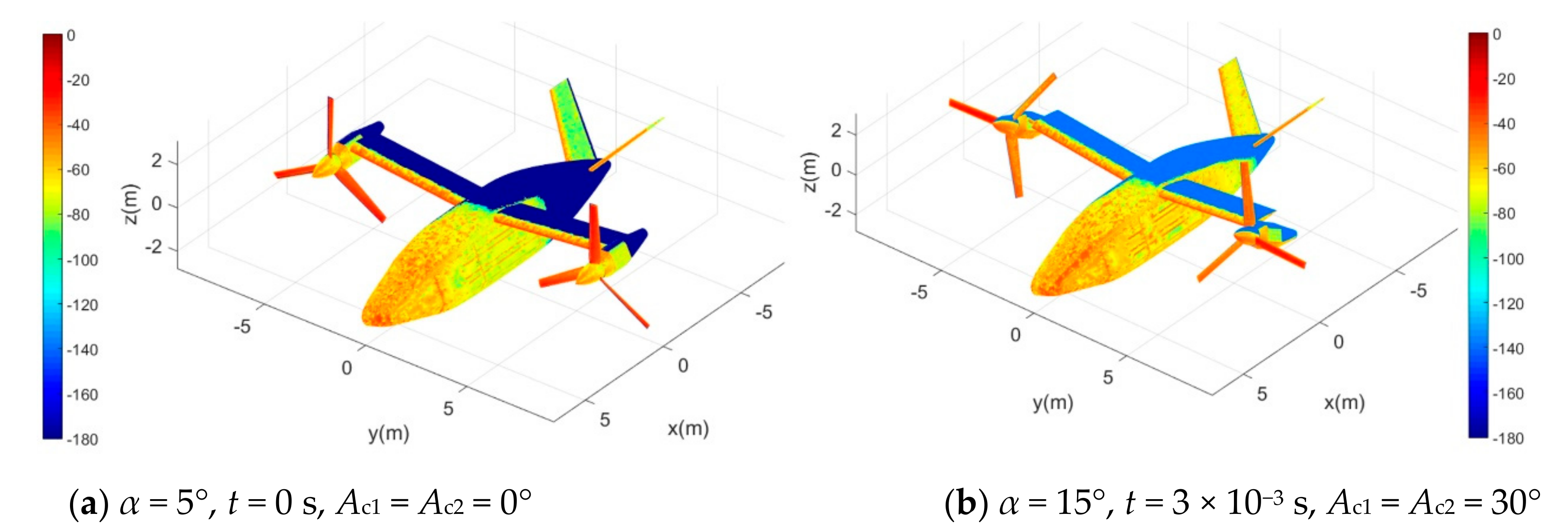
4.3. Investigation of Aircraft Surface Scattering

For the Figure 9a, under current conditions, the blades have the most obvious electromagnetic scattering characteristics, because the two rotor disks are perpendicular to the incident wave at this time, which makes each blade’s ability to deflect radar waves very weak. Note that the closer the color of the surface is to red, the larger the RCS of the face element is and the closer to the blue, the smaller the RCS of the face element is. At the leading edge of the wing, the curvature of the curved surface here varies greatly and there are many facets that are not conducive to deflecting radar waves; thus, the RCS level here is relatively high. In the indirect illumination area, the facets here do not receive the first illumination of the incident wave; thus, their scattering intensity is at the lowest level, showing blue and dark blue. When the cabin inclination angle is increased to 30° as shown in Figure 9b, the surface electromagnetic scattering characteristics of 2 blades on each rotor are significantly reduced. At this time, the azimuth angle increased to 15° and the original red of the leading edge of the wing was transformed into orange–red.
In Figure 10a, the abdomen of the two cabins appears redder and the electromagnetic scattering characteristics of the nose and propeller hub have been strengthened, because at this time, the angle between the rotor axis and the incident wave increases, the mirror reflection of the abdomen surface of the cabin and the arc cone of the hub is obvious and the curved surface near the rounded corner of the nose is not easy to deflect the radar wave. When the rotor axis is tilted to the vertical position as shown in Figure 10b, the cabin and the propeller hub become the strongest scattering sources. At this time, the illumination area on the side of the fuselage also appears more red and orange. In general, under the head-direction incident wave, the electromagnetic scattering characteristics of the fuselage and the vertical tail are generally better because of the use of stealth measures. When the rotor axis is turned from horizontal to vertical, the electromagnetic scattering characteristics of the blade surface can be improved, but the RCS level of the cabin has been enhanced.

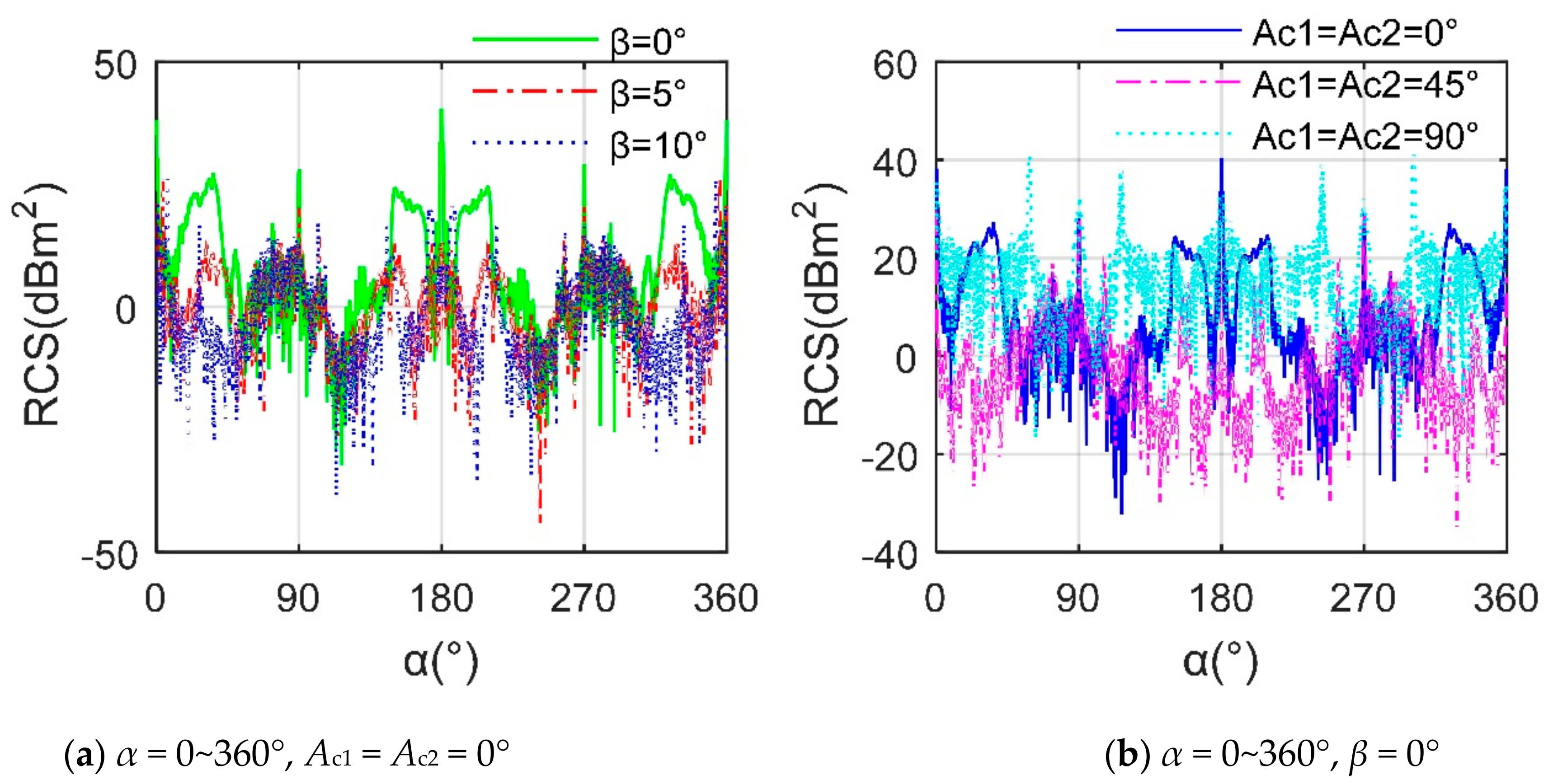
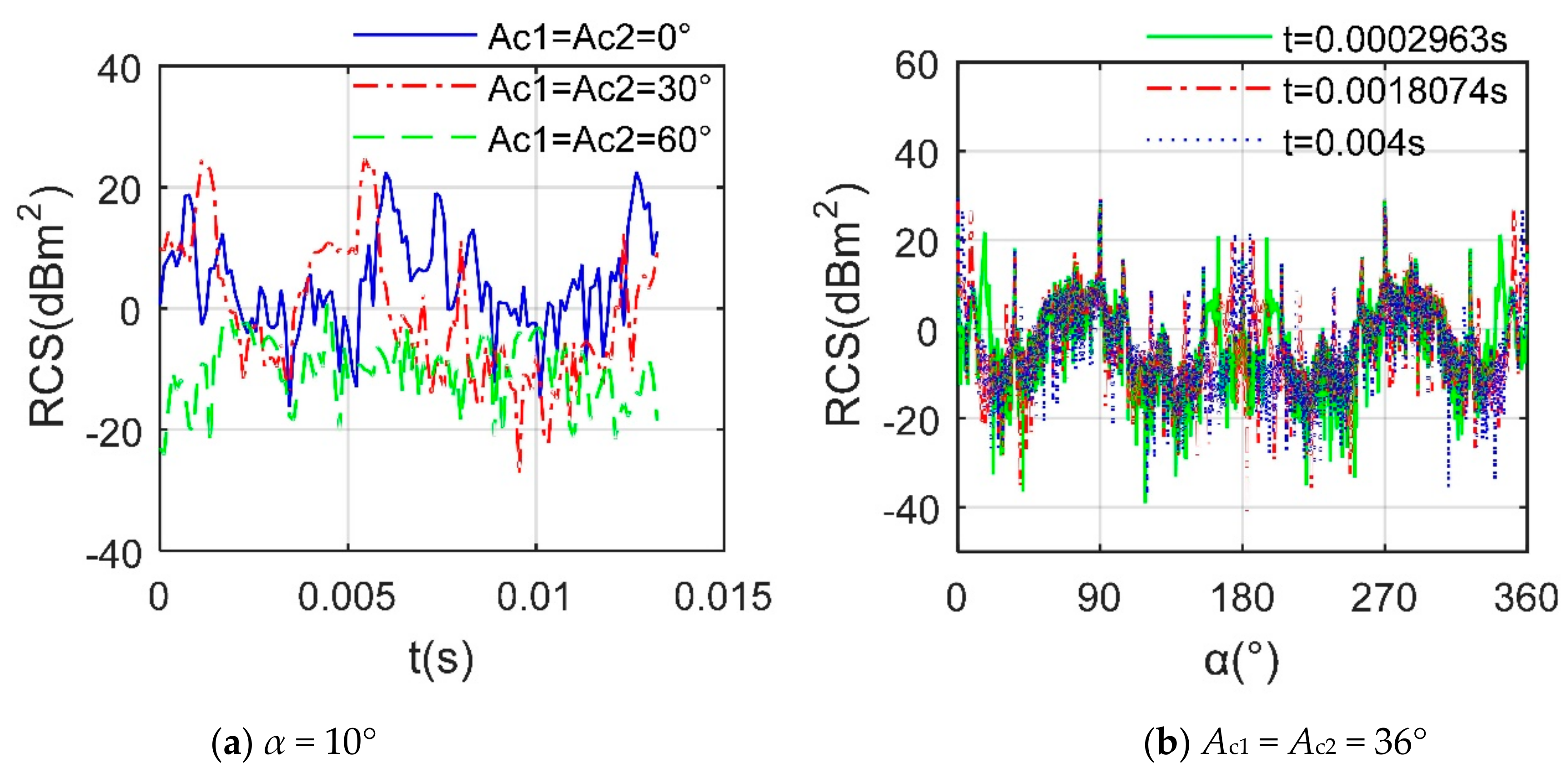
4.4. Effect of Tilting Action

With the increase of the elevation angle as shown in Figure 11a, the RCS~α of the aircraft in the initial state (t = 0 s) drops a lot, mainly in the peak, head and tail directions, where the average value of the RCS curve when β = 0° is 19.32 dBm2, while that of the other two curves is lower than 7.52 dBm2, because the increased elevation angle improves the angle between the incident wave and the rotor disk, it helps to reduce the high RCS caused by the blades. For the Figure 11b, the aircraft’s RCS average index decreased from 19.32 dBm2 to 8.68 dBm2 when the tilt angle increased from 0° to 45°, which is mainly due to the proper attitude of the rotor disc and cabin. As the tilt angle continues to increase to 90°, the average RCS increases to 24.02 dBm2, because although the RCS contribution of the rotor is less at this time, the abdomen of the cabin becomes a direct irradiation area and many strong scattering sources appear.
Considering the motion of the rotor, the aircraft’s RCS still presents dynamic characteristics under a fixed observation angle as shown in Figure 12a, where the average value of the RCS curve at a tilt angle of 0° and 30° is 11.35 dBm2 and 12.40 dBm2, respectively, while that at a tilt angle of 60° is as low as −7.70 dBm2. This implies that under the current observation angle, the aircraft is beneficial to stealth when flying at a cabin inclination of 60°. In Figure 12b, the RCS~α curve of the aircraft at different times is also different, where the RCS curve at t = 2.963 × 10⁻⁴ s has a local peak of 21.73 dBm2 at the azimuth angle of 17.25° and the ordinates of the other two RCS curves are less than −3.50 dBm2. The average value of the RCS curve at time t = 2.963 × 10⁻⁴ s is 8.12 dBm2 and that of the RCS curve at time t = 18.074 × 10⁻³ s and t = 0.004 s is 9.10 dBm2 and 9.06 dBm2. These results show that even if the cabin angle remains the same, the aircraft’s RCS~α will change significantly with the rotation of the rotor and the local RCS changes can be greater.
Further considering the dynamic influence of cabin tilting as shown in Figure 13a, the dynamic radar characteristics of the aircraft at different azimuths are different, including average level, fluctuation range and peak value, where ωc1 and ωc2 are the angular velocities of cabins 1 and 2, respectively. It can be noticed that the RCS curve under α = 0° basically has small fluctuations around 30 dBm2, where the maximum value is 35.08 dBm2 occurring at t = 0 s, the minimum value is 24.72 dBm2 at t = 6.75 s and the average value is 29.64 dBm2. When the radar wave is incident from the front where α = 0°, the cockpit, wing leading edge and tail of the aircraft provide more strong scattering sources and the rotor and cabin provide dynamic RCS contribution, thus, the average level of the entire RCS curve is high. The overall magnitude of the RCS curve under α = 10° and 20° is obviously lower, but the fluctuation range is large, where the average value of the former is 7.86 dBm2 and the average of the latter is 8.71 dBm2. As the azimuth angle of the incident wave increases, the strong scattering characteristics of the nose, cockpit and leading edge of the wing are changed and the dynamic RCS influence of the rotor and the cabin is enhanced. For the Figure 13b, the RCS~α curves of the aircraft at different times are also very different when the rotor rotation and cabin tilt are considered at the same time. The RCS~α curve of the aircraft under t = 2.0667 s shows two continuous “W” shapes as a whole, where the average value is 8.82 dBm2 and the peaks appear widely in the head, side and tail directions. At t = 8.7667 s, the mean value of the RCS curve has increased by 0.44 dBm2, which is compared with the RCS curve under t = 2.0667 s, while that under t = 15.25 s is as high as 15.63 dBm2, because the inclination angle of the two cabins has increased to 91.5° at this time, the middle and rear parts of the hub and the abdomen of the cabin have a strong specular reflection effect on the incident radar waves and the outer ends of the wings are no longer blocked by the cabins, this supports the increase in lateral RCS. As the tilt angle increases, the RCS performance in the tail direction first decreases and then increases. This is due to the increased scattering contribution from the upper surface of the cabin. The changes in the RCS curve under side direction of the aircraft at different times are also very obvious, while the amplitude is similar. These results indicate that the dynamic tilting action has a comprehensive impact on the stealth characteristics of the aircraft, including the RCS peak value at different azimuth angles, the fluctuation at different times and the average RCS index.
In general, the tilting motion of the cabin not only affects the electromagnetic scattering characteristics of itself and the rotor, but also changes the side RCS of the aircraft. This deformation of the aircraft shape makes the outer end of the wing easily exposed to the radiation of radar waves, which will contribute to the aircraft’s lateral RCS when there is no additional stealth measure. In the heading range, as the azimuth angle of the incident wave gradually increases, the electromagnetic scattering level of the side of the fuselage, the nose and the vertical tail is increased. The aircraft’s RCS level decreases significantly with the increase of the elevation angle, but generally decreases first and then increases with the increase of the cabin inclination angle. For the specified head incident wave, the dynamic RCS level of the aircraft under different cabin inclination angles is quite different, but there are cabin attitudes suitable for stealth flight. Even if the cabin attitude is fixed, the rotation of the rotor will bring changes to the RCS of the aircraft’s circumferential azimuth. Since the angular velocity of cabin tilting is much smaller than the angular velocity of the rotor, the dynamic RCS of the aircraft depends on the current observation time interval, but the rotation of the rotor cannot be ignored. For the simultaneous effect of rotor rotation and cabin tilting, the dynamic RCS of the aircraft still maintains a high level in the forward position. As the azimuth angle increases in the heading range, the RCS level will be weakened, but as the cabin approaches the vertical position, the aircraft’s dynamic RCS will increase significantly.

5. Conclusions

Based on the established dynamic scattering approach, the radar cross section of the tiltrotor under different influencing factors is investigated and analyzed. Based on the above research and discussion, this article can draw the following conclusions:
(1)
After the initial stealth design of the fuselage was adopted, the electromagnetic scattering level of the entire aircraft was well improved. However, in the fixed-wing mode, the rotor blades can still become a strong scattering source when facing the incident radar wave in the horizontal plane.
(2)
The increase in speed can shorten the period of the rotor dynamic RCS, while the rotating rotor makes the aircraft’s RCS exhibit different dynamic characteristics in helicopter mode, fixed-wing mode and transition mode.
(3)
Increasing the tilt angle can significantly improve the RCS performance of the rotor, but it will make the engine cabin and the outer end of the wing become a new source of strong scattering, which can provide a reference for the stealth optimization design of the cabin in future work.

Author Contributions

Conceptualization, Z.Z., J.H., C.C. and J.Z.; methodology, Z.Z. and J.H.; validation, Z.Z.; formal analysis, investigation, Z.Z., J.H., C.C. and J.Z.; writing—original draft preparation, Z.Z.; writing—review and editing, Z.Z. and J.H.; visualization, funding acquisition, Z.Z. All authors have read and agreed to the published version of the manuscript.

Funding

This research was supported by the project funded by China Postdoctoral Science Foundation (Grant Nos. BX20200035, 2020M680005).

Institutional Review Board Statement

Not applicable.

Informed Consent Statement

Not applicable.

Acknowledgments

Thanks to Jun Huang for his guidance on the research work of this manuscript. Thanks to all authors for their cooperation.

Conflicts of Interest

The authors declare that they have no competing interests.

References

  1. Aşırım, Ö.E.; Kuzuoğlu, M. Numerical study of resonant optical parametric amplification via gain factor optimization in dispersive microresonators. Photonics 2020, 7, 5. [Google Scholar] [CrossRef] [Green Version]
  2. Zhao, Q.; Jiang, S.; Li, P.; Wang, B.; Zhang, H. Aerodynamic optimization analyses of tiltrotor/propeller based on CFD method. Acta Aerodyn. Sin. 2017, 35, 544–553. [Google Scholar]
  3. Zhang, Y.; Zeng, F.; Dai, Q.; Wu, Z. Development status and trend of intelligent radar stealth technology. Tactical Missile Technol. 2019, 1, 56–63. [Google Scholar]
  4. Mirkovic, D.; Stepanian, P.M.; Kelly, J.F.; Chilson, P.B. Electromagnetic Model Reliably Predicts Radar Scattering Characteristics of Airborne Organisms. Sci. Rep. 2016, 6, 35637. [Google Scholar] [CrossRef]
  5. Zhou, Z.; Huang, J.; Yi, M. Comprehensive optimization of aerodynamic noise and radar stealth for helicopter rotor based on Pareto solution. Aerosp. Sci. Technol. 2018, 82, 607–619. [Google Scholar] [CrossRef]
  6. Bogatskaya, A.; Schegolev, A.; Klenov, N.; Popov, A. Generation of Coherent and Spatially Squeezed States of an Electromagnetic Beam in a Planar Inhomogeneous Dielectric Waveguide. Photonics 2019, 6, 84. [Google Scholar] [CrossRef] [Green Version]
  7. Ye, S.; Xiong, J. Dynamic RCS behavior of helicopter rotating blades. Acta Aeronaut. Astronaut. Sin. 2006, 27, 816–822. [Google Scholar]
  8. Jameson, A. Computational aerodynamics for aircraft design. Science 1989, 245, 361–371. [Google Scholar] [CrossRef] [Green Version]
  9. Konrad, T.G.; Hicks, J.J.; Dobson, E.B. Radar characteristics of birds in flight. Science 1968, 159, 274–280. [Google Scholar] [CrossRef]
  10. Li, P.; Zhao, Q. CFD calculations on the interaction flowfield and aerodynamic force of tiltrotor/wing in hover. Acta Aeronaut. Astronaut. Sin. 2014, 35, 362–372. [Google Scholar]
  11. Zhou, Z.; Huang, J. Influence of rotor dynamic scattering on helicopter radar cross-section. Sensors 2020, 20, 2097. [Google Scholar] [CrossRef] [Green Version]
  12. Komissarov, R.; Kozlov, V.; Filonov, D.; Ginzburg, P. Partially coherent radar unties range resolution from bandwidth limitations. Nat. Commun. 2019, 10, 1423. [Google Scholar] [CrossRef] [Green Version]
  13. Xiong, Y.; Ye, H.; Umeda, T.; Mizoguchi, S.; Morifuji, M.; Kajii, H.; Maruta, A.; Kondow, M. Photonic Crystal Circular Defect (CirD) Laser. Photonics 2019, 6, 54. [Google Scholar] [CrossRef] [Green Version]
  14. Chen, H.; Zuo, X.; Zhang, Y. Tiltrotor aircraft key technology developing research. Flight Dyn. 2007, 25, 6–9. [Google Scholar]
  15. Glover, K.M.; Hardy, K.R.; Konrad, T.G.; Sullivan, W.N.; Michaels, A.S. Radar observations of insects in free flight. Science 1966, 154, 967–972. [Google Scholar] [CrossRef]
  16. Zhou, Z.; Huang, J.; Wang, J. Electromagnetic scattering characteristics of coaxial helicopter based on dynamic transformation method. Chin. J. Aeronaut. 2020, 34, 516–528. [Google Scholar] [CrossRef]
  17. Zhou, Z.; Huang, J. Dynamic Scattering Approach for Solving the Radar Cross-Section of the Warship under Complex Motion Conditions. Photonics 2020, 7, 64. [Google Scholar] [CrossRef]
  18. Elachi, C. Spaceborne Imaging Radar Geologic and Oceanographic Applications. Science 1980, 209, 1073–1082. [Google Scholar] [CrossRef]
  19. Chen, X.; Wang, X.; Huang, Y.; Wang, X. Fault diagnosis for tiltrotor aircraft flight control system based on variable precision rough set-OMELM. Control Decis. 2015, 30, 434–441. [Google Scholar]
  20. Zhou, Z.; Huang, J.; Wang, J. Compound helicopter multi-rotor dynamic radar cross section response analysis. Aerosp. Sci. Technol. 2020, 105, 106047. [Google Scholar] [CrossRef]
  21. Schuck, M.; Steinert, D.; Nussbaumer, T.; Kolar, J.W. Ultrafast rotation of magnetically levitated macroscopic steel spheres. Sci. Adv. 2018, 4, e1701519. [Google Scholar] [CrossRef] [PubMed] [Green Version]
  22. Van Doren, B.M.; Horton, K.G. A continental system for forecasting bird migration. Science 2018, 361, 1115–1118. [Google Scholar] [CrossRef] [PubMed]
  23. Dai, H.; He, D. Areview of aircraft stealth and radar anti-stealth technology. Electron. Inf. Warf. Technol. 2016, 31, 41–44. [Google Scholar]
  24. Zhao, Y.; Liu, J. FDTD for hydrodynamic electron fluid Maxwell equations. Photonics 2015, 2, 459–467. [Google Scholar] [CrossRef] [Green Version]
  25. Gardner, A.D.; Wolf, C.C.; Raffel, M. Review of measurement techniques for unsteady helicopter rotor flows. Prog. Aerosp. Sci. 2019, 111, 100566. [Google Scholar] [CrossRef]
  26. Wang, R.; Hu, C.; Fu, X.; Long, T.; Zeng, T. Micro-Doppler measurement of insect wing-beat frequencies with W-band coherent radar. Sci. Rep. 2017, 7, 1396. [Google Scholar] [CrossRef] [PubMed] [Green Version]
  27. Carrer, L.; Bruzzone, L. Solving for ambiguities in radar geophysical exploration of planetary bodies by mimicking bats echolocation. Nat. Commun. 2017, 8, 1396. [Google Scholar] [CrossRef] [PubMed]
  28. Gao, L.; Reno, J.L.; Kumar, S. Short barriers for lowering current-density in terahertz quantum cascade lasers. Photonics 2020, 7, 7. [Google Scholar] [CrossRef] [Green Version]
  29. Yan, X.; Chen, R. Control strategy optimization of dynamic conversion procedure of tilt-rotor aircraft. Acta Aeronaut. Astronaut. Sin. 2017, 25, 520865. [Google Scholar]
  30. Rahman, S.; Robertson, D.A. Radar micro-Doppler signatures of drones and birds at K-band and W-band. Sci. Rep. 2018, 8, 17396. [Google Scholar] [CrossRef]
  31. Sareh, P.; Chermprayong, P.; Emmanuelli, M.; Nadeem, H.; Kovac, M. Rotorigami: A rotary origami protective system for robotic rotorcraft. Sci. Robot. 2018, 3, eaah5228. [Google Scholar] [CrossRef] [Green Version]
  32. Makinson, J.C.; Woodgate, J.L.; Reynolds, A.; Capaldi, E.A.; Perry, C.J.; Chittka, L. Harmonic radar tracking reveals random dispersal pattern of bumblebee (Bombus terrestris) queens after hibernation. Sci. Rep. 2019, 9, 4651. [Google Scholar] [CrossRef] [Green Version]
  33. Brocklehurst, A.; Barakos, G.N. A review of helicopter rotor blade tip shapes. Prog. Aerosp. Sci. 2013, 56, 35–74. [Google Scholar] [CrossRef]
  34. Mittapalli, V.; Khan, H. Excitation Schemes of Plasmonic Angular Ring Resonator-Based Band-Pass Filters Using a MIM Waveguide. Photonics 2019, 6, 41. [Google Scholar] [CrossRef] [Green Version]
  35. Wang, J.; Liu, Z.; Tian, Q.; Ji, J.; Yang, S. Analysis of influence of blade on electromagnetic scattering characteristics of heli-copter. Aeronaut. Comput. Tech. 2018, 48, 50–54. [Google Scholar]
  36. Tan, J.F.; Zhou, T.Y.; Sun, Y.M.; Barakos, G.N. Numerical investigation of the aerodynamic interaction between a tiltrotor and a tan-dem rotor during shipboard operations. Aerosp. Sci. Technol. 2019, 87, 62–72. [Google Scholar] [CrossRef] [Green Version]
  37. Chin, Y.W.; Kok, J.M.; Zhu, Y.Q.; Chan, W.L.; Chahl, J.S.; Khoo, B.C.; Lau, G.K. Efficient flapping wing drone arrests high speed flight using post-stall soaring. Sci. Robot. 2020, 5, eaba2386. [Google Scholar] [CrossRef]
  38. Barzanjeh, S.; Pirandola, S.; Vitali, D.; Fink, J.M. Microwave quantum illumination using a digital receiver. Sci. Adv. 2020, 6, eabb0451. [Google Scholar] [CrossRef]
Figure 1. Schematic of dynamic electromagnetic scattering of tilt rotor aircraft.
Photonics 08 00175 g001
Figure 2. Verification of DCM on rotor 1, β = 0°, frh = 10 GHz, nr1 = 1500 r/min, Ac1 =0°. (a) RCS curves at t = 5.33 × 10⁻³ s. (b) RCS curves at α = 30°.
Photonics 08 00175 g002
Figure 3. Model of the tiltrotor aircraft.
Photonics 08 00175 g003
Figure 4. High precision unstructured mesh for aircraft surface. (a) Aircraft grid. (b) Details of part grid.
Photonics 08 00175 g004
Figure 5. Surface electromagnetic scattering characteristics of rotor 1 and cabin 1, frh = 10 GHz, nr1= 1500 r/min, β = 0°, RCS unit: dBm2. (a) Surface scattering characteristics at α = 0°, t = 0 s, Ac1 = 0°. (b) Surface scattering characteristics at α = 10°, t = 1.333 × 10⁻³ s, Ac1 = 0°. (c) Surface scattering characteristics at α = 20°, t = 2.68 × 10⁻³ s, Ac1 = 0°. (d) Surface scattering characteristics at α = 0°, t = 0 s, Ac1 = 10°. (e) Surface scattering characteristics at α = 10°, t = 1.333 × 10⁻³ s, Ac1 = 10°. (f) Surface scattering characteristics at α = 20°, t = 2.68 × 10⁻³ s, Ac1 = 30°.
Photonics 08 00175 g005aPhotonics 08 00175 g005b
Figure 6. RCS curve of rotor 1, t = 0 s, Ac1 = 0°, fr represents the frequency of the radar wave, HH means horizontal polarization, VV means vertical polarization. (a) RCS curves of rotor 1. (b) RCS mean of rotor 1, α = 0~360°.
Photonics 08 00175 g006
Figure 7. RCS curves of different components, Ac1 = 0°, frh = 10 GHz. (a) RCS level comparison, t = 0 s, Ac2 = 0°. (b) RCS curves of rotor 1, α = 30°.
Photonics 08 00175 g007
Figure 8. Dynamic RCS of different components, frh = 10 GHz, nr1 = 1500 r/min. (a) Dynamic RCS of rotor 1, Ac1 = 0°. (b) Dynamic RCS of rotor 1 + cabin 1.
Photonics 08 00175 g008
Figure 9. Surface scattering characteristics of aircraft, β = 0°, frh = 10 GHz, nr1 = nr2 = 1500 r/min, RCS unit: dBm2. (a) SurFigure 5. t = 0 s, Ac1 = Ac2 = 0°. (b) Surface scattering characteristics at α = 15°, t = 3 × 10⁻³ s, Ac1 = Ac2 = 30°.
Photonics 08 00175 g009
Figure 10. Surface scattering of the aircraft, β = 0°, frh = 10 GHz, nr1 = nr2 = 1500 r/min, RCS unit: dBm2. (a) Surface scattering at α = 25°, t = 5.93 × 10⁻³ s, Ac1 = Ac2 = 60°. (b) Surface scattering at α = 35°, t = 8.89 × 10⁻³ s, Ac1 = Ac2 = 90°.
Photonics 08 00175 g010
Figure 11. RCS of the tilt rotor aircraft, frh = 10 GHz, t = 0 s, nr1 = nr2 = 1500 r/min. (a) RCS curves at α = 0~360°, Ac1 = Ac2 = 0°. (b) RCS curves at α = 0~360°, β = 0°.
Photonics 08 00175 g011
Figure 12. RCS curves of the tilt rotor aircraft, frh = 10 GHz, β = 0°, nr1 = nr2 = 1500 r/min. (a) RCS curve at α = 10°. (b) RCS curve at Ac1 = Ac2 = 36°.
Photonics 08 00175 g012
Figure 13. RCS of the tilt rotor aircraft, frh = 10 GHz, β = 0°, nr1 = nr2 = 1500 r/min, ωc1 = ωc2 = 10.472 × 10⁻² rad/s. (a) RCS curves at RCS at α = [0, 10, 20]°. (b) RCS curves at various time.
Photonics 08 00175 g013
Table 1. The size distribution of the surface grid of each part of the aircraft.
AreaMax Size (mm)AreaMax Size (mm)
Global minimum size1Trailing edge of rotor 12
Trailing edge of rotor 22Leading edge of rotor 13
Leading edge of rotor 23Blade tip5
Hub edge10Blade surface25
Hub surface30Cabin surface30
Wing edge15Fuselage surface35
Publisher’s Note: MDPI stays neutral with regard to jurisdictional claims in published maps and institutional affiliations.

