Abstract
We theoretically research the four-wave mixing (FWM) and second-order sideband generation (SSG) in a hybrid optomechanical system under the condition of pump on-resonance and pump off-resonance, where an optomechanical resonator is coupled to another nanomechanical resonator (NR) via Coulomb interaction. Using the standard quantum optics method and input–output theory, we obtain the analytical solution of the FWM and SSG with strict derivation. According to the numerical simulations, we find that the FWM can be controlled via regulating the coupling strength and the frequency difference of the two NRs under different detuning, which also gives a means to determine the coupling strength of the two NRs. Furthermore, the SSG is sensitive to the detuning, which shows double second-order optomechanically induced transparency (OMIT) sidebands via controlling the coupling strength and frequencies of the resonators. Our investigation may increase the comprehension of nonlinear phenomena in hybrid optomechanics systems.
1. Introduction
Cavity optomechanics (COM) systems [1,2] (as a milestone [3] in optics history), which investigates the interaction of electromagnetic fields and micromechanical motion, have witnessed significant progress over the past decade both in fundamental studies and practical applications including ground state cooling [4,5,6,7,8], mass sensing [9,10], high-precision measurements [11,12,13,14,15,16,17], and quantum information processing [18,19,20,21]. The mechanical motions in COM systems, due to the radiation pressure forces, are tunable by optomechanical interactions, which in turn influence the optical medes resulting in prominent quantum interference effects. There are many famous phenomena that have been obtained in COM systems, such as phonon lasers [22,23,24,25], squeezing [26,27], entanglement [20,21], nonreciprocity [28,29,30], exceptional point (EP) devices [24,25,31,32], optomechanically induced transparency (OMIT) [33,34,35,36,37,38,39,40], and OMIT induced slow and fast light [36,41,42,43,44]. We notice that many above phenomena remain in the linear optical regime.
COM systems also present a medium to research the nonlinear phenomena between the electromagnetic field light and matter. Optical bistability [45,46,47,48,49], as a representative nonlinear phenomena, has been extensively investigated in some kinds of COM systems. In the COM systems, if the cavity is driven by a strong pump laser field (with frequency ) and a weak probe laser field (with frequency ), then when the two pump photons mix with a probe photon, an idler photon at frequency will emerge, as a result the four-wave mixing (FWM) appear in the ouput field, which has been investigated in different optomechanical systems [50,51,52,53]. Except nonlinear phenomena of optical bistability and FWM, recently, another remarkable nonlinear optomechanical effect, i.e., the second-order sideband generation (SSG), has also been demonstrated in COM systems [54,55,56,57,58,59,60,61,62,63,64], where the SSG will appear in the output fields with frequencies ( is the probe-pump detuning) and () is the second-order upper (lower) sideband frequency component. However, the FWM and SGG in a hybrid optomechanical system, where a typical optomechanical cavity coupled to another NR via Coulomb interaction has not been demonstrated until now.
In this paper, we investigate the FWM and SSG in a hybrid optomechanical system as shown in Figure 1 under the condition of pump on-resonance and off-resonance. The location of sideband peaks both in the FWM spectrum and SSG depends on the resonator frequencies and the Coulomb interaction of the two NRs. In particular, the different frequencies of the resonators also alter the location of the peaks in the FWM spectrum and SSG. Interestingly, in the pump off-resonance regime, the FWM spectrum can indicate a means to measure the Coulomb interaction, and we obtain double second-order OMIT sideband, which is sensitive to the Coulomb interaction and different resonator frequencies.
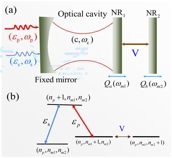
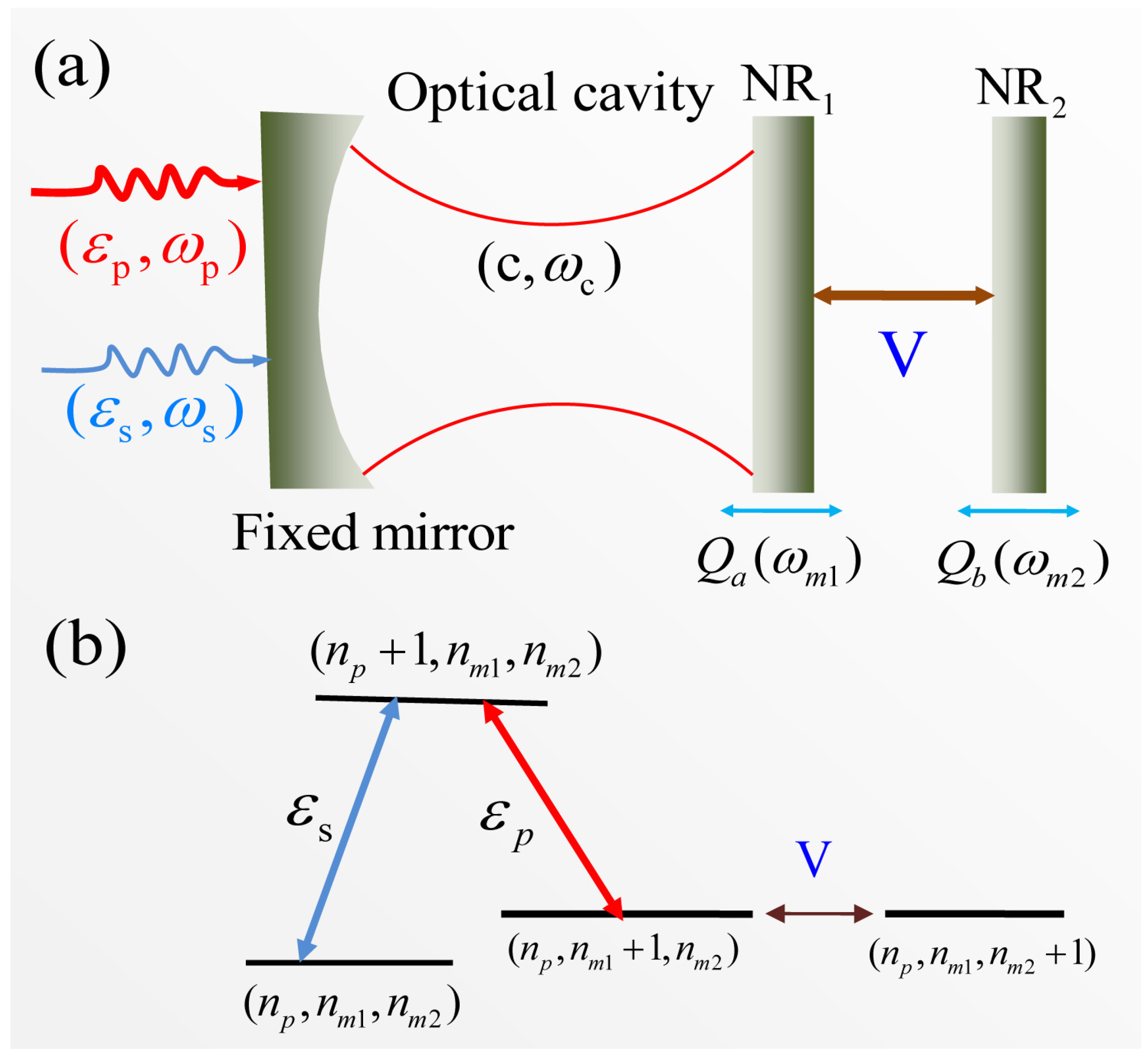
Figure 1.
(a) Schematic diagram of the hybrid coupled optomechanical system including two coupled nanomechanical resonators (NRs) via Coulomb interaction. (b) Schematic of the energy-level diagram of the system. , , and denote the number states of the cavity photon, the phonons of NR and NR, respectively. V is the coupling strength of the two NRs.
2. System and Method
The hybrid optomechanical system is shown in Figure 1, which includes a Fabry–Perot (FP) optomechanical cavity coupling to another NR via Coulomb interaction, and the Hamiltonian can be given by [65,66,67]
where the first term gives the cavity field (with frequency ) and we use the creation (annihilation) operator (c) to describe the optical cavity. The second and third terms shows two NRs with the frequencies and , and are the creation and annihilation operators of the two NRs, respectively. The fourth term gives the optomechanical coupling with coupling strength , where is the effective mass of NR and L is the cavity length. The fifth term describes the interaction of two charged NRs with coupling strength V via the Coulomb interaction [65,66,67]. As the cavity is driven by a two-tone fields, we define and as the amplitudes of the two laser fields, and and are their powers. is extra loss rate and here we consider , where is the intrinsic loss rate of photon with the relation of .
We can rewrite Equation (1) in the following in a frame rotating with the frequency [65,66,67]
where is the cavity-pump detuning. We then obtain the Langevin equations (LEs) as follows with adding the corresponding damping and input noise terms [33,35,65,66,67]
where the input vacuum noise is denoted by with zero mean value, and and are Langevin force arising from the environment. and are the decay rates of the two NRs. and are the position operators of the two NRs.
Due to the pump field being stronger than the probe field, we use the conversion of (), i.e., the operators are divided into the steady-state mean value and a small fluctuation. For the steady-state values, which is determined by the following equations
where , , , and . In the condition of mean-field approximation, the operators can be replaced by their expectation values [33], For the fluctuation operators, we also use their expectation values with neglecting nonlinear terms, and we obtain the expectation values of the LEs [33]
In order to solve Equations (9)–(11), we use the ansatz as [68]
and substituting Equation (12) into Equations (9)–(11), we can obtian two group equations with ignoring the terms higher than the second-order. The first group describe the first-order sideband as following
where , , , and . Solving the equations, we can obtain
where , , and .
The second group gives the SSG progress as
where , , , and . Solving the equations, we can obtain
where , , and .
According to the optical cavity input and output theory [69] , we then reach the following relation
where the first term is the output field with the frequency , the second one indicates output field with the frequency , and the third term denotes FWM process with the requency . The forth and fifth terms shows the SSG process where (i.e., ) is the second-order upper sideband and (i.e., ) is the second-order lower sideband. We introduce a dimensionless FWM intensity to study the FWM process [70]
In order to research the second-order process conveniently, we use a dimensionless efficiency of SSG as [54,55,56,57,62,64]
The parameter values used in the paper [71] are: nm, mm, kHz, , , ng, kHz, W, and .
3. Results and Discussion
3.1. The FWM Process
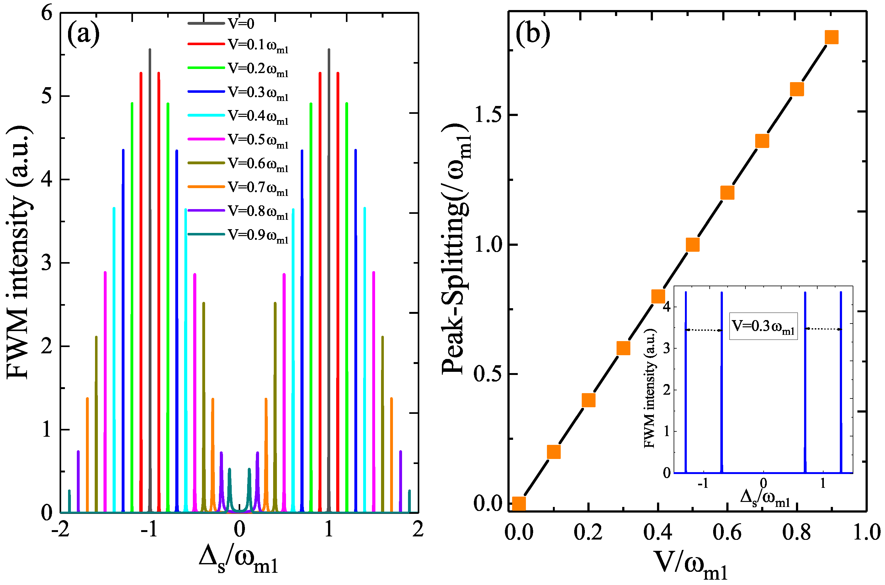
The FWM process has been demonstrated in optomechanical systems [50,51,70], which depends on the intracavity photon number in Equation (20). However, in our hybrid optomechanical system, we concentrate on another two parameters, i.e., the coupling strength V and the frequency difference of the two NRs. Figure 2a plots the FWM spectrum as a function of the probe-cavity detuning for several different coupling strength V with the parameters of the pump power W and the same frequencies under the condition of pump on-resonance (). In the case of , i.e., the typical FP optomechanical system without considering another NR, we find two sharp sideband peaks (the black curve in Figure 2a) in the FWM spectrum accurately locating at the resonator frequency , which can be attributed to the quantum interference of the phonon mode and the beat frequency of two optical fields. Then, if the beat frequency is close to the resonator frequency , the resonator starts to oscillate coherently leading to Stokes () scattering of light from the optomechanical system. However, when another NR is taken into consideration (), the sideband peaks locates at splits into two peaks, and with increasing V from to , the width of the splitting in the FWM spectra is broadening at the expense of intensity as shown the color curves in Figure 2a. When we measure the sideband peaks splitting width of the FWM spectrum under , we find that the relation between the splitting width and the coupling strength V of the two NRs is linear as shown in Figure 2b, and the inset in Figure 2b gives the FWM spectrum at a fixed coupling strength . The result will give a method the measure the coupling strength V of the two NRs and we will discuss the result in the following.

Figure 2.
(a) The FWM spectrum versus the probe-cavity detuning for several different coupling strengths V with the parameters W and at . (b) the peak splitting of the two sideband peaks versus the coupling strength V, and the inset in (b) give the FWM spectrum at a fixed .
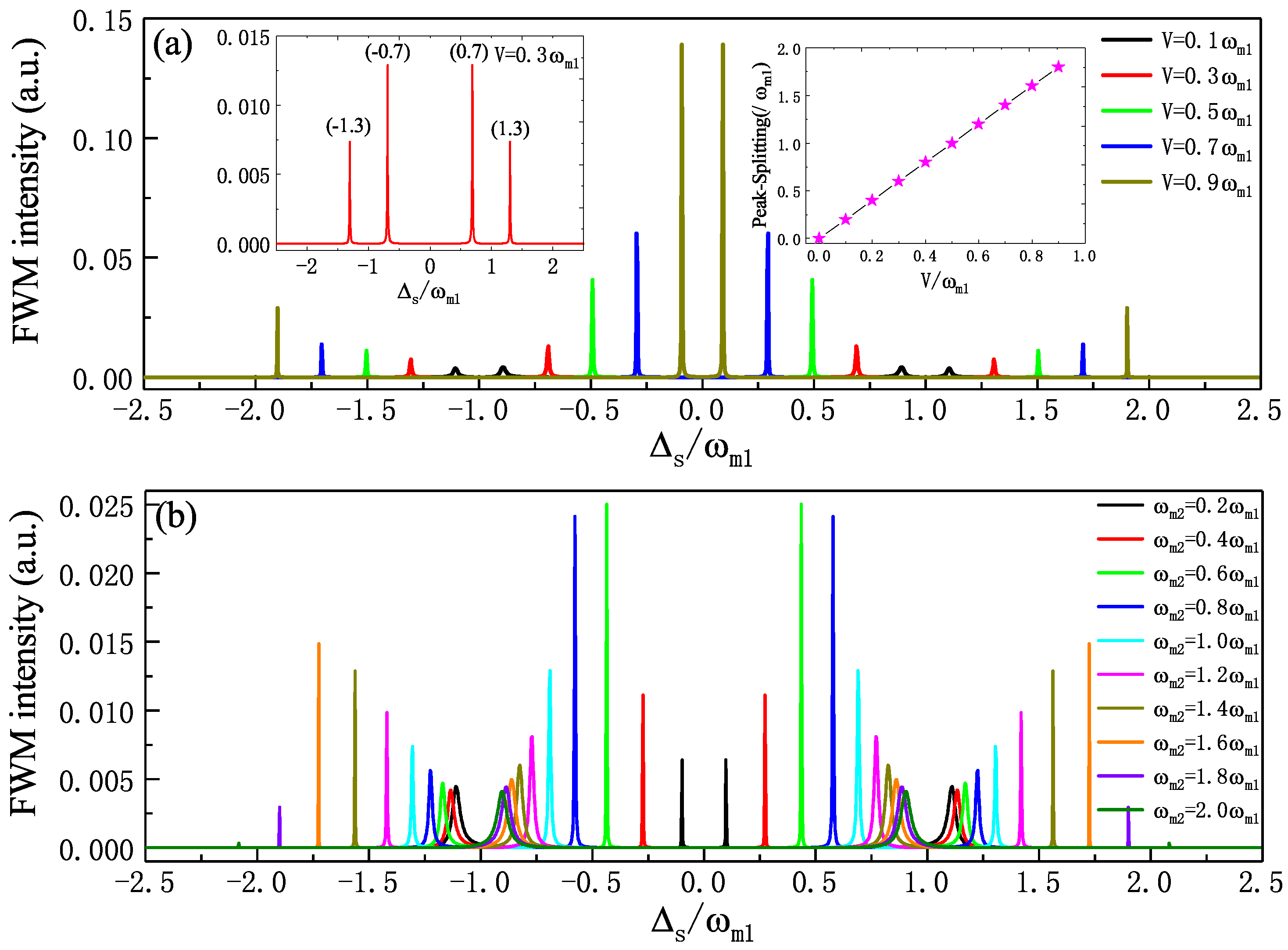
Switching the condition to pump off-resonance, i.e., , we investigate the FWM process under different parametric regimes. In Figure 3a, we plot the FWM spectra for five different coupling strengths V at W and in the case of red sideband (). We can see that there are four sharp sideband peaks in the FWM spectra, which presents mirror symmetry for , and the splitting of both sides of the peaks is broadening with enhanced intensity of the FWM spectra for increasing the coupling strength V from to . In addition, the location of the sideband peaks is related to the coupling strength V. We take as an example as shown the left inset in Figure 3a, we see that the left two peaks locate at and , i.e., ; while the right two peaks locate at and , i.e., . When measuring the width of the splitting of both of the two sideband peaks in the FWM spectra, we find the width of the splitting is related to the coupling strength V as shown the right inset in Figure 3a, which plots the splitting of both of the two sideband peaks versus the coupling strength V. Obviously, the splitting width relies linearly on the coupling strength V and reaches to 0 in the absence of the coupling, which presents an effective means to determine the coupling strength V of the two NRs. Thus, we can measure the coupling strength V of the two NRs via only simply measuring the splitting distance of two sideband peaks in the FWM spectrum. Moreover, we also study the FWM spectrum for different resonator frequencies at a fixed coupling strength V. In Figure 3b, we show the FWM spectra as a function of for several different resonator frequencies with the parameters of W and in the case of . We find that the peaks in the left part is left-shift and the peaks in the right part is right-shift with increasing the frequency from to , and both the intensities of two sideband peaks experience the process of enhancement to decrease. As in Equations (9)–(11), where and , i.e., the effective frequencies of the two NRs are modulated by the coupling strength V of the two NRs. In Figure 3b, we set a fixed coupling strength , if the two NRs are identical resonators, i.e., the two NRs own the same frequencies , which is demonstrated in Figure 3a and the splitting width of the sideband peaks in the FWM spectrum is proportional to the coupling strength V. In the case of , i.e., , the FWM spectra is squeezed and both the two sideband peaks move to . In the case of , i.e., , the FWM spectra is expanded and the sideband peaks move to both sides. Compared with FWM process in the optomechanical system only including one mechanical mode and one optical mode [72,73], the intensity of the FWM in our hybrid system is enhanced significantly modulated by another NR.
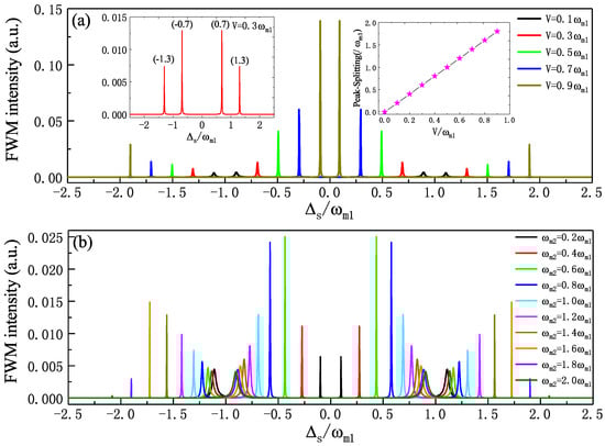
Figure 3.
(a) The FWM spectra for five different coupling strengths V at W and in the case of , and the left inset is , the right inset plots the splitting of the two sideband peaks as a function of the coupling strength V. (b) The FWM spectra as a function of for several different resonator frequencies with the parameters and in the case of .
3.2. The SSG Process
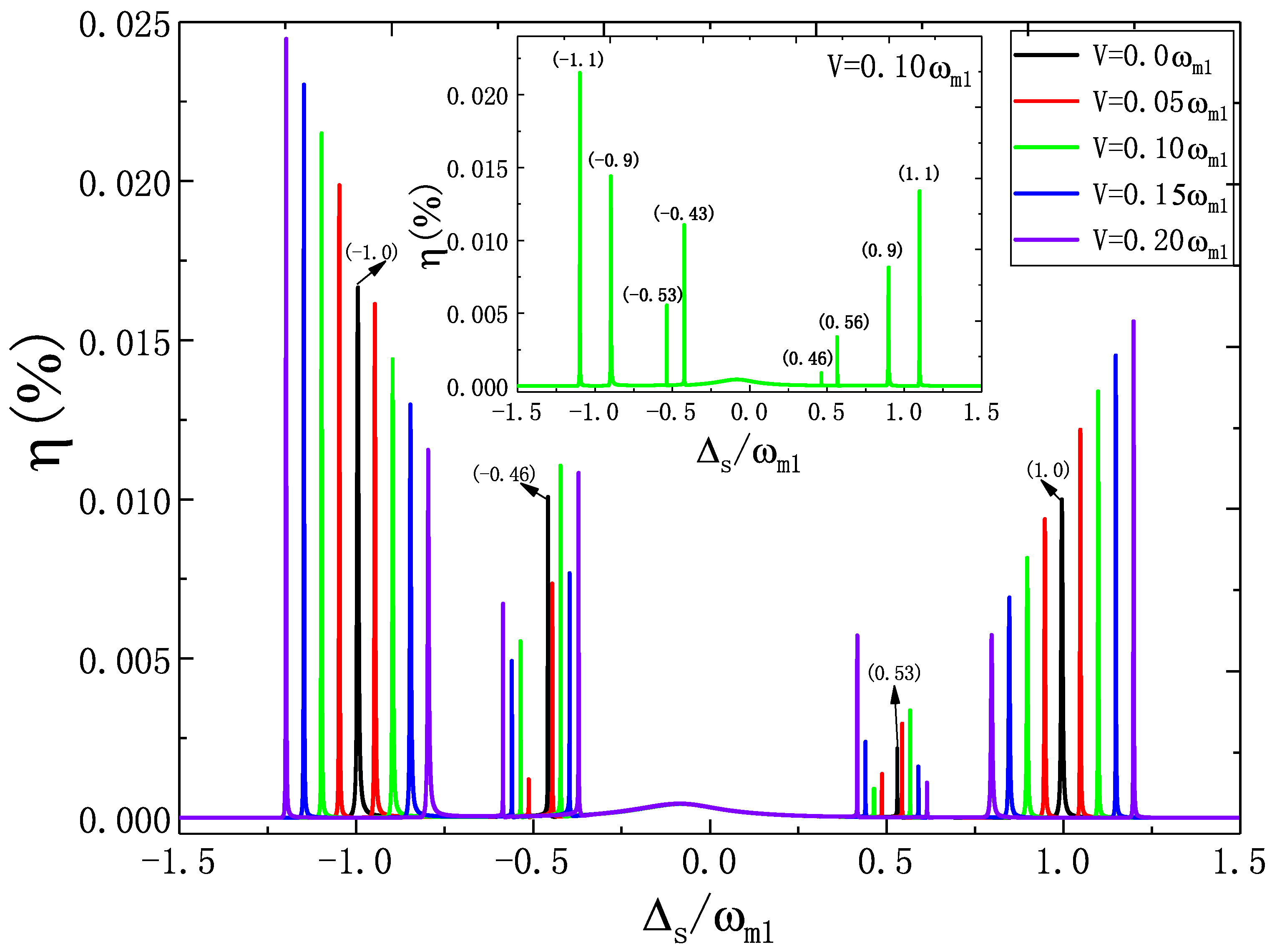
On the other hand, the SSG is also a distinguished nonlinear phenomenon in optomechanical systems, and Equation (21) gives the dimensionless efficiency of the SSG process. As we know, if the optomechanical system is driven by a two-tone field, the output field with frequency (i.e., ) is the second-order upper sideband and the output field with frequency (i.e., ) is the second-order lower sideband. Here, we concentrate on the second-order upper sideband () and study the coupling strength V and the frequency difference of the two NRs the affect the SSG process for different detuning. In Figure 4, we show the efficiency of SSG as a function of the normalized probe detuning for several different coupling strengths V with the parameters of the pump power W and the same frequencies under the condition of pump on-resonance . If the system is the typical FP optomechanical system without considering another NR, i.e., , as shown the black curve in Figure 4, it is clear that four sideband peaks emerge in the efficiency of SSG, where two principal sideband peaks locate at and another two secondary sideband peaks locate at with a small shift. We accurately identify the location of the principal sideband peaks at and secondary sideband peaks at and , respectively, as shown the black curve in Figure 4. When another NR is considered (), we find that both the principal sideband peaks locating at and the secondary sideband peaks around split into two peaks, and then eight sideband peaks appear in efficiency of SSG. Here, we take as an example as shown the inset in Figure 4. The splitting of principal sideband peaks locate at and (i.e., ), and and (i.e., ) with the width of splitting of 2 V. The splitting of secondary sideband peaks are located at (−0.53, −0.43) and (0.46, 0.56), i.e., and , respectively, with the width of splitting of V.
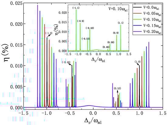
Figure 4.
The efficiency of SSG versus for several different coupling strengths V with the parameters W and under the condition of , and the inset gives the condition of .
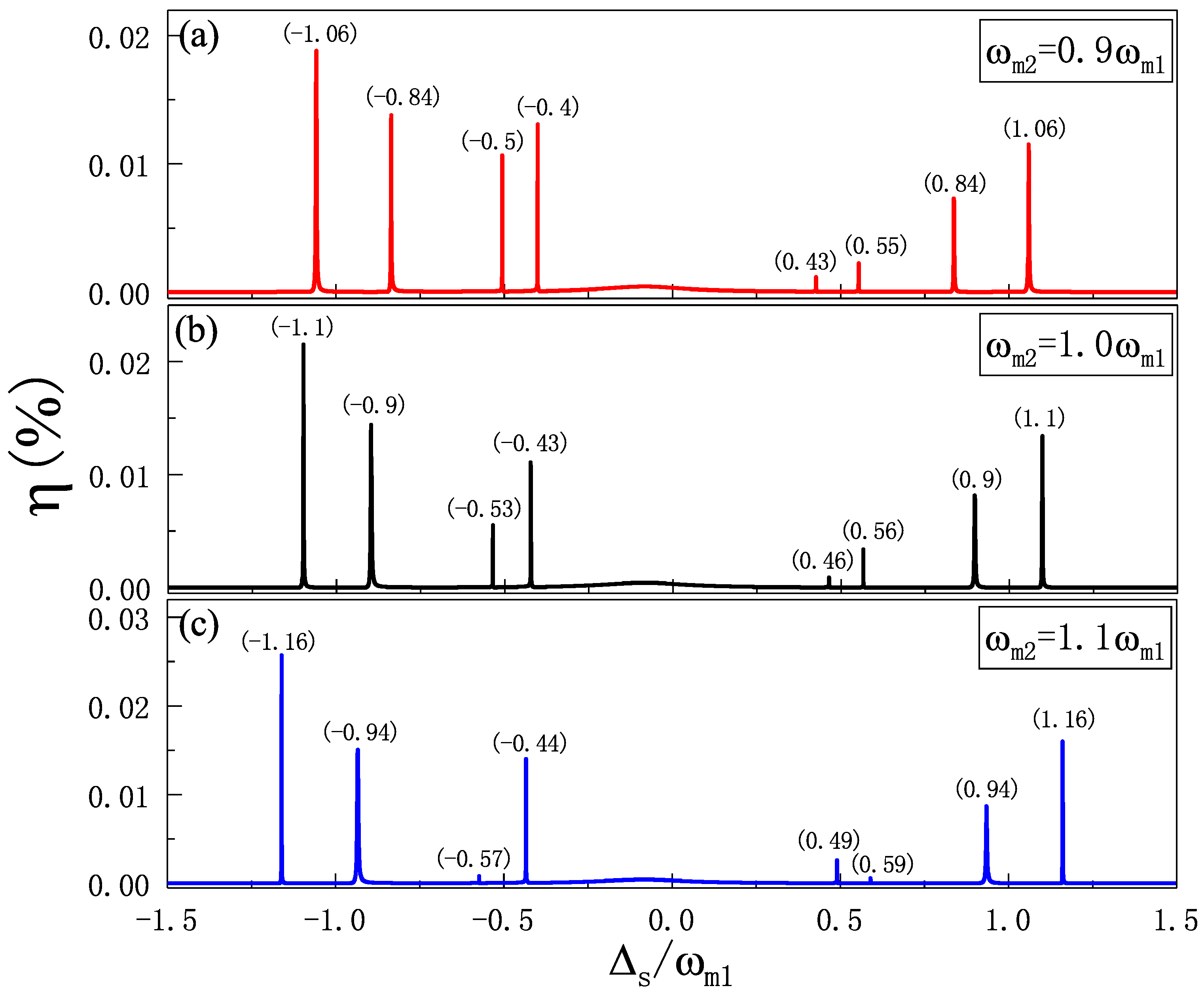
Moreover, we also investigate the different resonator frequencies of the two NRs that influence the SSG process as shown in Figure 5. Figure 5b gives the efficiency of SSG versus for the same frequencies of the two NRs at the parameters of W and under the pump on-resonance , which manifests four principal sideband peaks locating at and four secondary sideband peaks locating around , and the precise locations are marked in Figure 5b. If as shown in Figure 5a, we find the spectrum of the SSG is squeezed, while if as shown in Figure 5c, we can see that the spectrum of the SSG is stretched, and the accurate locations are identified in Figure 5a,c, respectively.
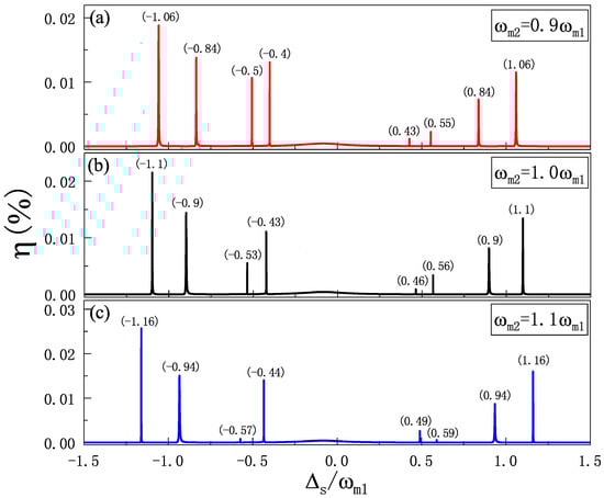
Figure 5.
(a) The efficiency of SSG as a function of for . (b) The efficiency of SSG as a function of for . (c) The efficiency of SSG as a function of for . The other parameters are , , and .
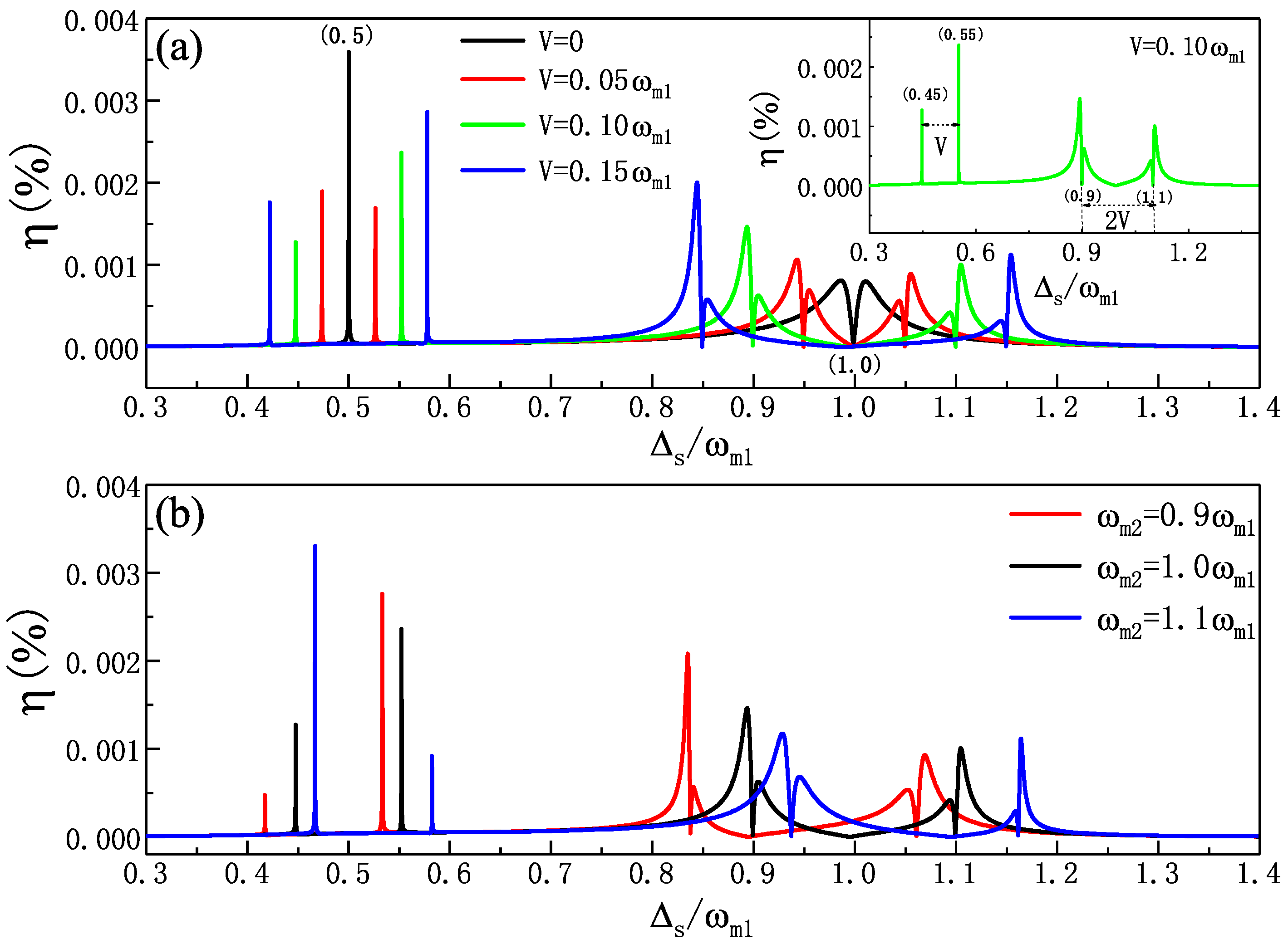
Then, we further research the SSG for several different parametric regimes in the condition of . Figure 6a presents the efficiency of SSG versus with four different coupling strengths V at W and the same frequencies . When as shown the black curve in Figure 6a, i.e., without considering another NR, we find that not only a second-order sharp single peak locating at but also a second-order OMIT sideband locating at with symmetrical splitting appear in the SSG spectrum. Once another NR is taken into consideration, i.e., , we can obtain two significant phenomena in the SSG spectra: (a) the single peak locating at splits into two peaks; (b) the second-order OMIT sideband locating at splits into double second-order OMIT sideband with asymmetrical splitting. The phenomenon originates from the coupling between NR and NR which not only adds a fourth level, as shown in Figure 1b, but also breaks down the symmetrical second-order OMIT sideband due to quantum interference and, therefore, induces sharp bright resonance within the second-order OMIT sideband. It is obvious that due to the interaction of the two NRs via Coulomb interaction, the coupled number states of the photon and phonons are induced. Then, the symmetrical second-order OMIT sideband is split into two asymmetrical double second-order OMIT sideband. Here, we take as an example as shown in the inset of Figure 6a, we find the two splitting peaks located at 0.45 and 0.55 with the width V of the splitting, i.e., the two sharp peaks locate at . While another double asymmetrical second-order OMIT sidebands locate at 0.9 and 1.1 with the width 2 V of the splitting, i.e., the double second-order OMIT sidebands locate at . With further increasing the coupling strengths V of the two NRs, both the splitting of the two sharp peaks and the double second-order OMIT sidebands are enhanced. Moreover, we also investigate the frequency difference of the two NRs that affect the efficiency of SSG. In Figure 6b, we show the efficiency of SSG as a function of for three different frequencies at W and . It is obvious that the SSG spectra show two splitting peaks around and double asymmetrical second-order OMIT sidebands around , and if , the SSG spectrum shifts to the left, if , the SSG spectrum shifts to the right. Therefore, the double second-order OMIT sidebands can be controlled with manipulating the coupling strength V and the frequency difference of the two resonators.
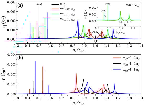
Figure 6.
(a) The efficiency of SSG four different coupling strengths V with the parameters of W and at , and the inset gives as an example. (b) The efficiency of SSG as a function of for three different frequencies at W and .
Compared with the SSG in the typical FP optomechanical system without considering another NR, there are several advantages of the SSG in our hybrid optomechanical system. In the condition of , if only one NR in the system (), the SSG spectrum presents the sharp principal sideband peaks at and secondary sideband peaks around , while if another NR is considered () in the case of identical NRs with the same frequencies (), both the sharp principal sideband peaks and secondary sideband peaks are split into two peaks, and the splitting width of the principal sideband peaks is linear with respect to the coupling strength V of the two NRs, which indicates a method to precisely determine the coupling strength V of the two NRs. In addition, if the two NRs are different with different frequencies (), the location of sharp sideband peaks in the SSG spectra are tunable. On the other hand, in the condition of pump off-resonance, i.e., , the SSG shows a second-order OMIT sideband [64] at , while if another NR is taken into consideration (), the SSG displays double second-order OMIT sidebands which is very different from the case of . Therefore, the SSG process can be tunable via controlling the coupling of the two NRs.
4. Conclusions
We theoretically demonstrated the FWM and SSG in a hybrid COM system which is driven by a two-tone field for different detuning conditions, where an optomechanical resonator is coupled to another NR via Coulomb interaction. We first studied the FWM under the condition of pump on-resonance and pump off-resonance, when the coupling strength V of the two NRs is considered, the FWM presents four modes splitting, which gives a method to determine the coupling strength V. In addition, the frequency difference of the two NRs also alter the FWM process. On the other hand, another nonlinear phenomena of the SSG process has also demonstrated both in pump on-resonance and red sideband with controlling the parameters of the coupling strength V and the frequency difference of the two NRs. Moreover, the SSG is sensitive to the detuning, which displays the double asymmetrical second-order OMIT sidebands via controlling V and frequencies of the resonators, which may indicate a further insight of nonlinear optomechanical phenomena and may find important applications fot manipulating light propagation and quantum communications based on the hybrid optomechanical system.
Funding
This research was funded by National Natural Science Foundation of China (Nos:11647001 and 11804004), Project funded by China Postdoctoral Science Foundation (No:2020M681973) and Anhui Provincial Natural Science Foundation (No:1708085QA11).
Institutional Review Board Statement
Not applicable.
Informed Consent Statement
Not applicable.
Data Availability Statement
Not applicable.
Acknowledgments
Huajun Chen is supported by the National Natural Science Foundation of China (Nos:11647001 and 11804004), Project funded by China Postdoctoral Science Foundation (No:2020M681973) and Anhui Provincial Natural Science Foundation (No:1708085QA11).
Conflicts of Interest
The authors declare that they have no known competing financial interests or personal relationships that could have appeared to influence the work reported in this paper.
References
- Aspelmeyer, M.; Kippenberg, T.J.; Marquardt, F. Cavity optomechanics. Rev. Mod. Phys. 2014, 86, 1391. [Google Scholar] [CrossRef]
- Metcalfe, M. Applications of cavity optomechanics. App. Phys. Rev. 2014, 1, 031105. [Google Scholar] [CrossRef]
- Milestones: Photons. Available online: https://www.nature.com/milestones/milephotons/timeline.html (accessed on 24 June 2021).
- Schliesser, A.; Riviere, R.; Anetsberger, G.; Arcizet, O.; Kippenberg, T.J. Resolved-sideband cooling of a micromechanical oscillator. Nat. Phys. 2008, 4, 415–419. [Google Scholar] [CrossRef] [Green Version]
- Teufel, J.D.; Donner, T.; Li, D.; Harlow, J.W.; Allman, M.S.; Cicak, K.; Sirois, A.J.; Whittaker, J.D.; Lehnert, K.W.; Simmonds, R.W. Sideband cooling of micromechanical motion to the quantum ground state. Nature 2011, 475, 359–363. [Google Scholar] [CrossRef] [Green Version]
- Chan, J.; Alegre, T.P.M.; Safavi-Naeini, A.H.; Hill, J.T.; Krause, A.; Groblacher, S.; Aspelmeyer, M.; Painter, O. Laser cooling of a nanomechanical oscillator into its quantum ground state. Nature 2011, 478, 89–92. [Google Scholar] [CrossRef] [Green Version]
- Chen, X.; Liu, Y.-C.; Peng, P.; Zhi, Y.; Xiao, Y.-F. Cooling of macroscopic mechanical resonators in hybrid atomoptomechanical systems. Phys. Rev. A 2015, 92, 033841. [Google Scholar] [CrossRef]
- Lai, D.-G.; Zou, F.; Hou, B.-P.; Xiao, Y.-F.; Liao, J.-Q. Simultaneous cooling of coupled mechanical resonators in cavity optomechanics. Phys. Rev. A 2018, 98, 023860. [Google Scholar] [CrossRef] [Green Version]
- Li, J.J.; Zhu, K.D. All-optical mass sensing with coupled mechanical resonator systems. Phys. Rep. 2013, 525, 223–254. [Google Scholar] [CrossRef]
- Jiang, C.; Cui, Y.; Zhu, K.D. Ultrasensitive nanomechanical mass sensor using hybrid opto-electromechanical systems. Opt. Express 2014, 22, 13773. [Google Scholar] [CrossRef]
- Schliesser, A.; Arcizet, O.; Riviere, R.; Anetsberger, G.; Kippenberg, T.J. Resolved-sideband cooling and position measurement of a micromechanical oscillator close to the Heisenberg uncertainty limit. Nat. Phys. 2009, 5, 509. [Google Scholar] [CrossRef] [Green Version]
- Basiri-Esfahani, S.; Akram, U.; Milburn, G.J. Phonon number measurements using single photon opto-mechanics. New J. Phys. 2012, 14, 085017. [Google Scholar] [CrossRef] [Green Version]
- Gavartin, E.; Verlot, P.; Kippenberg, T.J. A hybrid on-chip optomechanical transducer for ultrasensitive force measurements. Nat. Nanotechnol. 2012, 7, 509–514. [Google Scholar] [CrossRef] [PubMed] [Green Version]
- Krause, A.G.; Winger, M.; Blasius, T.D.; Lin, Q.; Painter, O. A high-resolution microchip optomechanical accelerometer. Nat. Photon. 2012, 6, 768–772. [Google Scholar] [CrossRef] [Green Version]
- Schreppler, S.; Spethmann, N.; Brahms, N.; Botter, T.; Barrios, M.; Stamper-Kurn, D.M. Optically measuring force near the standard quantum limit. Science 2014, 344, 1486–1489. [Google Scholar] [CrossRef] [PubMed] [Green Version]
- Xiong, H.; Si, L.G.; Wu, Y. Precision measurement of electrical charges in an optomechanical system beyond linearized dynamics. Appl. Phys. Lett. 2017, 110, 171102. [Google Scholar] [CrossRef]
- Matsumoto, N.; Catano-Lopez, S.B.; Sugawara, M.; Suzuki, S.; Abe, N.; Komori, K.; Michimura, Y.; Aso, Y.; Edamatsu, K. Demonstration of Displacement Sensing of a mg-Scale Pendulum for mm- and mg-Scale Gravity Measurements. Phys. Rev. Lett. 2019, 122, 071101. [Google Scholar] [CrossRef] [Green Version]
- Wang, Y.D.; Clerk, A.A. Using interference for high fidelity quantum state transfer in optomechanics. Phys. Rev. Lett. 2012, 108, 153603. [Google Scholar] [CrossRef]
- Tian, L. Adiabatic state conversion and pulse transmission in optomechanical systems. Phys. Rev. Lett. 2012, 108, 153604. [Google Scholar] [CrossRef] [Green Version]
- Tian, L. Robust photon entanglement via quantum interference in optomechanical interfaces. Phys. Rev. Lett. 2013, 110, 233602. [Google Scholar] [CrossRef]
- Wang, Y.D.; Clerk, A.A. Reservoir-engineered entanglement in optomechanical systems. Phys. Rev. Lett. 2013, 110, 253601. [Google Scholar] [CrossRef] [PubMed] [Green Version]
- Grudinin, I.S.; Lee, H.; Painter, O.; Vahala, K.J. Phonon laser action in a tunable two-level system. Phys. Rev. Lett. 2010, 104, 083901. [Google Scholar] [CrossRef]
- Zhang, J.; Peng, B.; Ozdemir, S.K.; Pichler, K.; Krimer, D.O.; Zhao, G.; Nori, F.; Liu, Y.; Rotter, S.; Yang, L. A phonon laser operating at an exceptional point. Nat. Photonics 2018, 12, 479–484. [Google Scholar] [CrossRef]
- Jing, H.; Ozdemir, S.K.; Lü, X.Y.; Zhang, J.; Yang, L.; Nori, F. PT-symmetric phonon laser. Phys. Rev. Lett. 2014, 113, 053604. [Google Scholar] [CrossRef] [Green Version]
- Lü, H.; Ozdemir, S.K.; Kuang, L.M.; Nori, F.; Jing, H. Exceptional points in random-defect phonon lasers. Phys. Rev. Appl. 2017, 8, 044020. [Google Scholar] [CrossRef] [Green Version]
- Safavi-Naeini, A.H.; Groeblacher, S.; Hill, J.T.; Chan, J.; Aspelmeyer, M.; Painter, O. Squeezed light from a silicon micromechanical resonator. Nature 2013, 500, 185–189. [Google Scholar] [CrossRef] [Green Version]
- Agarwal, G.S.; Huang, S.M. Strong mechanical squeezing and its detection. Phys. Rev. A 2016, 93, 043844. [Google Scholar] [CrossRef] [Green Version]
- Manipatruni, S.; Robinson, J.T.; Lipson, M. Optical nonreciprocity in optomechanical structures. Phys. Rev. Lett. 2009, 102, 213903. [Google Scholar] [CrossRef] [PubMed] [Green Version]
- Xu, X.W.; Li, Y.; Chen, A.X.; Liu, Y.X. Nonreciprocal conversion between microwave and optical photons in electro-optomechanical systems. Phys. Rev. A 2016, 93, 023827. [Google Scholar] [CrossRef] [Green Version]
- Jiang, C.; Song, L.N.; Li, Y. Directional amplifier in an optomechanical system with optical gain. Phys. Rev. A 2018, 97, 053812. [Google Scholar] [CrossRef] [Green Version]
- Lü, X.-Y.; Jing, H.; Ma, J.-Y.; Wu, Y. PT -symmetry-breaking chaos in optomechanics. Phys. Rev. Lett. 2015, 114, 253601. [Google Scholar] [CrossRef] [Green Version]
- Xu, H.; Mason, D.; Jiang, L.; Harris, J.G.E. Topological energy transfer in an optomechanical system with exceptional points. Nature 2016, 537, 80–83. [Google Scholar] [CrossRef] [PubMed] [Green Version]
- Agarwal, G.S.; Huang, S. Electromagnetically induced transparency in mechanical effects of light. Phys. Rev. A 2010, 81, 041803. [Google Scholar] [CrossRef] [Green Version]
- Liu, Y.-C.; Li, B.-B.; Xiao, Y.-F. Electromagnetically induced transparency in optical microcavities. Nanophotonics 2017, 6, 789–811. [Google Scholar] [CrossRef]
- Weis, S.; Riviere, R.; Deleglise, S.; Gavartin, E.; Arcizet, O.; Schliesser, A.; Kippenberg, T.J. Optomechanically induced transparency. Science 2010, 330, 1520–1523. [Google Scholar] [CrossRef] [PubMed] [Green Version]
- Safavi-Naeini, A.H.; Alegre, T.P.M.; Chan, J.; Eichenfield, M.; Winger, M.; Lin, Q.; Hill, J.T.; Chang, D.E.; Painter, O. Electromagnetically induced transparency and slow light with optomechanics. Nature 2011, 472, 69–73. [Google Scholar] [CrossRef] [PubMed] [Green Version]
- Teufel, J.D.; Li, D.; Allman, M.S.; Cicak, K.; Sirois, A.J.; Whittaker, J.D.; Simmonds, R.W. Circuit cavity electromechanics in the strong-coupling regime. Nature 2011, 471, 204–208. [Google Scholar] [CrossRef] [PubMed] [Green Version]
- Fan, L.; Fong, K.Y.; Poot, M.; Tang, H.X. Cascaded optical transparency in multimode-cavity optomechanical systems. Nat. Commun. 2015, 6, 5850. [Google Scholar] [CrossRef]
- Dong, C.; Zhang, J.; Fiore, V.; Wang, H. Optomechanically induced transparency and self-induced oscillations with Bogoliubov mechanical modes. Optica 2014, 1, 425. [Google Scholar] [CrossRef]
- Lü, H.; Jiang, Y.; Wang, Y.Z.; Jing, H. Optomechanically induced transparency in a spinning resonator. Photonics Res. 2017, 5, 367–371. [Google Scholar] [CrossRef]
- Jiang, C.; Liu, H.X.; Cui, Y.S.; Li, X.W.; Chen, G.B.; Chen, B. Electromagnetically induced transparency and slow light in two-mode optomechanics. Opt. Express 2013, 21, 12165. [Google Scholar] [CrossRef] [Green Version]
- Zhou, X.; Hocke, F.; Schliesser, A.; Marx, A.; Huebl, H.; Gross, R.; Kippenberg, T.J. Slowing, advancing and switching of microwave signals using circuit nanoelectromechanics. Nat. Phys. 2013, 9, 179–184. [Google Scholar] [CrossRef] [Green Version]
- Fiore, V.; Dong, C.; Kuzyk, M.C.; Wang, H. Optomechanical light storage in a silica microresonator. Phys. Rev. A 2013, 87, 023812. [Google Scholar] [CrossRef] [Green Version]
- Chen, H.-J.; Hou, B.-C.; Yang, J.-Y. Controllable coherent optical response in a ring cavity optomechanical system. Phys. E 2021, 125, 114394. [Google Scholar] [CrossRef]
- Sete, E.A.; Eleuch, H. Controllable nonlinear effects in an optomechanical resonator containing a quantum well. Phys. Rev. A 2012, 85, 043824. [Google Scholar] [CrossRef]
- Kanamoto, R.; Meystre, P. Optomechanics of a quantum-degenerate Fermi gas. Phys. Rev. Lett. 2010, 104, 063601. [Google Scholar] [CrossRef] [Green Version]
- Purdy, T.P.; Brooks, D.W.C.; Botter, T.; Brahms, N.; Ma, Z.-Y.; Stamper-Kurn, D.M. Tunable cavity optomechanics with ultracold atoms. Phys. Rev. Lett. 2010, 105, 133602. [Google Scholar] [CrossRef] [PubMed] [Green Version]
- Yan, D.; Wang, Z.H.; Ren, C.N.; Gao, H.; Li, Y.; Wu, J.H. Duality and bistability in an optomechanical cavity coupled to a Rydberg superatom. Phys. Rev. A 2015, 91, 023813. [Google Scholar] [CrossRef]
- Xiong, W.; Jin, D.Y.; Qiu, Y.; Lam, C.H.; You, J.Q. Cross-Kerr effect on an optomechanical system. Phys. Rev. A 2016, 93, 023844. [Google Scholar] [CrossRef] [Green Version]
- Huang, S.; Agarwal, G.S. Normal-mode splitting and antibunching in Stokes and anti-Stokes processes in cavity optomechanics: Radiation-pressure-induced four-wave-mixing cavity optomechanics. Phys. Rev. A 2010, 81, 033830. [Google Scholar] [CrossRef] [Green Version]
- Jia, W.Z.; Wei, L.F.; Li, Y.; Liu, Y. Phase-dependent optical response properties in an optomechanical system by coherently driving the mechanical resonator. Phys. Rev. A 2015, 91, 043843. [Google Scholar] [CrossRef] [Green Version]
- Xu, X.W.; Li, Y. Controllable optical output fields from an optomechanical system with mechanical driving. Phys. Rev. A 2015, 92, 023855. [Google Scholar] [CrossRef] [Green Version]
- Chen, H.J.; Wu, H.W.; Yang, J.Y.; Li, X.C.; Sun, Y.J.; Peng, Y. Controllable Optical Bistability and Four-Wave Mixing in a Photonic-Molecule Optomechanics. Nanoscale Res. Lett. 2019, 14, 73–82. [Google Scholar] [CrossRef] [PubMed]
- Xiong, H.; Si, L.G.; Zheng, A.S.; Yang, X.; Wu, Y. Higher-order sidebands in optomechanically induced transparency. Phys. Rev. A 2012, 86, 013815. [Google Scholar] [CrossRef] [Green Version]
- Suzuki, H.; Brown, E.; Sterling, R. Nonlinear dynamics of an optomechanical system with a coherent mechanical pump: Second-order sideband generation. Phys. Rev. A 2015, 92, 033823. [Google Scholar] [CrossRef] [Green Version]
- Jiao, Y.; Lu, H.; Qian, J.; Li, Y.; Jing, H. Nonlinear optomechanics with gain and loss: Amplifying higher-order sideband and group delay. New J. Phys. 2016, 18, 083034. [Google Scholar] [CrossRef]
- Li, J.; Li, J.; Xiao, Q.; Wu, Y. Giant enhancement of optical high-order sideband generation and their control in a dimer of two cavities with gain and loss. Phys. Rev. A 2016, 93, 063814. [Google Scholar] [CrossRef]
- Xiong, H.; Si, L.-G.; Lu, X.-Y.; Wu, Y. Optomechanically induced sum sideband generation. Opt. Express 2016, 24, 5773. [Google Scholar] [CrossRef] [PubMed]
- Xiong, H.; Fan, Y.-W.; Yang, X.; Wu, Y. Radiation pressure induced difference-sideband generation beyond linearized description. Appl. Phys. Lett. 2016, 109, 061108. [Google Scholar] [CrossRef]
- Kong, C.; Xiong, H.; Wu, Y. Coulomb-interaction-dependent effect of high-order sideband generation in an optomechanical system. Phys. Rev. A 2017, 95, 033820. [Google Scholar] [CrossRef] [Green Version]
- Si, L.-G.; Guo, L.-X.; Xiong, H.; Wu, Y. Tunable high-order-sideband generation and carrier-envelope-phase–dependent effects via microwave fields in hybrid electro-optomechanical systems. Phys. Rev. A 2018, 97, 023805. [Google Scholar] [CrossRef]
- Jiao, Y.-F.; Lu, T.-X.; Jing, H. Optomechanical second-order sidebands and group delays in a Kerr resonator. Phys. Rev. A 2018, 97, 013843. [Google Scholar] [CrossRef] [Green Version]
- Yellapragada, K.C.; Pramanik, N.; Singh, S.; Lakshmi, P.A. Optomechanical effects in a macroscopic hybrid system. Phys. Rev. A 2018, 98, 053822. [Google Scholar] [CrossRef]
- Chen, B.; Shang, L.; Wang, X.-F.; Chen, J.-B.; Xue, H.-B.; Liu, X.; Zhang, J. Atom-assisted second-order sideband generation in an optomechanical system with atom-cavity-resonator coupling. Phys. Rev. A 2019, 99, 063810. [Google Scholar] [CrossRef]
- Ma, P.-C.; Zhang, J.-Q.; Xiao, Y.; Feng, M.; Zhang, Z.-M. Tunable double optomechanically induced transparency in an optomechanical system. Phys. Rev. A 2014, 90, 043825. [Google Scholar] [CrossRef] [Green Version]
- Wang, Q.; Zhang, J.Q.; Ma, P.C.; Yao, C.M.; Feng, M. Precision measurement of the environmental temperature by tunable double optomechanically induced transparency with a squeezed field. Phys. Rev. A 2015, 91, 063827. [Google Scholar] [CrossRef] [Green Version]
- Wu, S.-C.; Qin, L.-G.; Jing, J.; Yan, T.-M.; Lu, J.; Wang, Z.-Y. Microwave-controlled optical double optomechanically induced transparency in a hybrid piezo-optomechanical cavity system. Phys. Rev. A 2018, 98, 013807. [Google Scholar] [CrossRef] [Green Version]
- Boyd, R.W. Nonlinear Optics; Academic: San Diego, CA, USA, 1992; p. 225. [Google Scholar]
- Gardiner, C.W.; Zoller, P. Quantum Noise; Springer: Berlin, Germany, 2000. [Google Scholar]
- Jiang, C.; Cui, Y.; Liu, H. Controllable four-wave mixing based on mechanical vibration in two-mode optomechanical systems. Europhys. Lett. 2013, 104, 34004. [Google Scholar] [CrossRef]
- Groblacher, S.; Hammerer, K.; Vanner, M.R.; Aspelmeyer, M. Observation of strong coupling between a micromechanical resonator and an optical cavity field. Nature 2009, 460, 724–727. [Google Scholar] [CrossRef] [PubMed] [Green Version]
- Jiang, C.; Chen, B.; Zhu, K.D. Controllable nonlinear responses in a cavity electromechanical system. J. Opt. Soc. Am. B 2012, 29, 220–225. [Google Scholar] [CrossRef]
- Xing, H.W.; Chen, B.; Xing, L.L.; Chen, J.B.; Xue, H.B.; Guo, K.X. Controllable four-wave mixing based on quantum dot-cavity coupling system. Commun. Theor. Phys. 2021, 73, 055101. [Google Scholar] [CrossRef]
Publisher’s Note: MDPI stays neutral with regard to jurisdictional claims in published maps and institutional affiliations. |
© 2021 by the author. Licensee MDPI, Basel, Switzerland. This article is an open access article distributed under the terms and conditions of the Creative Commons Attribution (CC BY) license (https://creativecommons.org/licenses/by/4.0/).