Article

Multicolor Holographic Display of 3D Scenes Using Referenceless Phase Holography (RELPH)

1
Bremer Institut für Angewandte Strahltechnik GmbH (BIAS), Klagenfurter Str. 5, 28359 Bremen, Germany
2
Faculty of Physics and Electrical Engineering and MAPEX, University of Bremen, Otto-Hahn-Allee NW 1, 28359 Bremen, Germany
*
Author to whom correspondence should be addressed.
Photonics 2021, 8(7), 247; https://doi.org/10.3390/photonics8070247
Submission received: 9 June 2021 / Revised: 24 June 2021 / Accepted: 25 June 2021 / Published: 30 June 2021
(This article belongs to the Special Issue Holography)

Abstract

:
In this paper, we present a multicolor display via referenceless phase holography (RELPH). RELPH permits the display of full optical wave fields (amplitude and phase) using two liquid crystal phase-only spatial light modulators in a Michelson-interferometer-based arrangement. Complex wave fields corresponding to arbitrary real or artificial 3D scenes are decomposed into two mutually coherent wave fields of constant amplitude whose phase distributions are modulated onto the wave fields reflected by the respective light modulators. Here, we present the realization of that concept in two different ways: firstly, via temporal multiplexing using a single setup, switching between wavelengths for temporal integration of the respective wavefields; secondly, using spatial multiplexing of different wavelengths with multiple Michelson-based setups; and finally, we present an approach to magnify the 3D scenes displayed by light modulators with limited space–bandwidth product for a comfortable viewing experience.

1. Introduction

Holography still represents—at least in principle—the gold standard of three-dimensional display [1,2,3]. In contrast to volumetric displays [4,5] as well as stereoscopic or light field technologies [6,7], it allows to satisfy all depth cues of the human perception, including full parallax, a large depth of field, and a wide angle of view [8]. While holography is well-established in the case of static scenes, it still remains a technological challenge to realize dynamic holographic displays. One of the primary problems is the low space–bandwidth product (SBP) of currently available dynamic spatial light modulators (SLM) [9]. To overcome the problem of low SBP, approaches including temporal multiplexing [10,11,12,13], spatial multiplexing [14], a combination of static and dynamic light modulators [15], rewritable photographic media [16] or eye-tracking [17,18] have been investigated.
Regardless of limitations due to the SBP of available SLMs, there have been considerable efforts towards dynamical holographic multicolor displays, superpositioning multiple colors through frequency domain multiplexing [19,20], temporal multiplexing [21,22] or spatial multiplexing [23]. To improve the image quality of these multicolor holographic displays, multiple techniques have been investigated, including deep neural networks [24], camera-in-the-loop techniques [25], as well as the combination of holography with light field-based approaches [26].
Recently, referenceless phase holography (RELPH) has been introduced [27,28], which aims at the efficient use of the available SBP of current SLMs. Instead of recreating the holographically recorded interference pattern, as obtained from the superposition of an object wave with a reference wave, it makes use of multiple phase-only SLMs to generate a desired complex amplitude at a given plane in space. The great advantage is that no zero-order and no pseudoscopic images arise, leading to an optimum use of the available SBP.
In this paper, we present the multicolor holographic display of 3D scenes by the RELPH method. To reconstruct the wave fields, we use a Michelson-interferometer-based setup with two SLMs modulating the respective phase distributions. We propose two different methods for multicolor display, firstly by temporal multiplexing of three different wavelengths, displayed in temporal sequence. The second given color multiplexing method is based on superpositioning the reconstructed holographic wave fields of different wavelengths spatially. For this, two separate Michelson-based setups are used, where the simultaneous spatial superposition of the respective reconstructed wave fields results in a multicolor impression.

2. Mathematical Description and Experimental Setup

2.1. Mathematical Description of RELPH

The holographical display of 3D scenes is based on the reconstruction of complex 2D diffraction fields in a given hologram plane ( x , y ) [29]. The diffraction field E ( x , y ) , with the intensity distribution I ( x , y ) and the phase distribution ϕ ( x , y ) , can, without loss of generality, be normalized for the intensity distribution to have values only within the interval [ 0 , 4 ] [27]. Any such wave field E can be decomposed into two mutually coherent wave fields, E 1 ( x , y ) and E 2 ( x , y ) , consisting of pure phase distributions, ϕ 1 ( x , y ) and ϕ 2 ( x , y ) , with a constant amplitude,
E ( x , y ) = I ( x , y ) · exp [ i ϕ ( x , y ) ] = E 1 ( x , y ) + E 2 ( x , y ) = exp [ i ϕ 1 ( x , y ) ] + exp [ i ϕ 2 ( x , y ) ] ,
where the two phase distributions are given by
ϕ 1 ( x , y ) = ϕ ( x , y ) + arctan ( ( 4 I ( x , y ) ) / I ( x , y ) )
ϕ 2 ( x , y ) = ϕ ( x , y ) arctan ( ( 4 I ( x , y ) ) / I ( x , y ) ) ,
as shown in [27].
To find the wave field E ( x , y ) necessary to display a 3D object holographically, the object is sliced into 2D planes. Each plane ( ε , η , z ) contains the 3D objects’ points at the z-coordinate of the respective plane, with E ( ε , η , z ) being the wave field emitted from these object points. The wave field distribution E ( x , y ) in the SLM plane ( z = 0 ) is calculated by propagating each individual wave field E ( ε , η , z ) into that plane by the angular spectrum method [30]. The individually propagated wave fields from each z-coordinate are summed up for coherent superposition in the SLM plane,
E ( x , y ) = z g F 1 F E ( ε , η , z ) · H ( f x , f y ) ,
H ( f x , f y ) = e i z 2 π / λ 1 ( λ f x ) 2 ( λ f y ) 2 , if f x 2 + f y 2 < 1 / λ 0 otherwise
where the sum is written over the z-coordinates of the individual slices along a linear array g, with the transfer function H. F denotes the two-dimensional Fourier transform, with the spatial frequencies in Fourier space f x = 1 N Δ ε , f y = 1 M Δ η , as defined by the discrete Fast Fourier Transform. Here, N , M are the number of pixels and Δ ε , Δ η are the pixel pitches of the SLMs in vertical and horizontal directions, and λ is the wavelength. The intensity and phase distributions I ( x , y ) and ϕ ( x , y ) are then calculated from this propagated and superpositioned wave field E ( x , y ) to find the phase distributions ϕ 1 ( x , y ) , ϕ 2 ( x , y ) for each SLM according to Equations (2) and (3).

2.2. Setup of RELPH

The 3D scenes are displayed using two identical phase-only liquid crystal spatial light modulators (SLM) in a Michelson-interferometer-based setup shown in Figure 1a. The superposition of the two wave fields given by Equation (1) is realized by placing one SLM in each interferometer arm of a Michelson-interferometer. Due to the SLMs birefringence, a polarizer is placed in front of the beam-splitter, corresponding to the slow axis of the SLMs, as well as an additional (optional) analyzer after the beam-splitter. For a multicolor display, three lasers with different wavelengths corresponding to the three fundamental colors, red, green, and blue are used. The light coming from the lasers is parallelized and expanded by three lenses to produce plane waves with the diameter of the SLMs. A 3D display via the RELPH method using such a setup has previously been shown to display the 3D cues’ depth of field, occlusion, and parallax [28].
For spatial multiplexing of two wave fields with different colors, two Michelson-based setups are coupled via an additional beam-splitter, as shown in Figure 1b. Generally, the optical path between the SLM planes of the respective RELPH setups and the additional beam-splitter will differ. This has to be taken into account when defining the imaging planes for the respective setups. Three-dimensional scenes can be displayed as real images between the SLM plane and the viewer or as virtual images behind the SLM plane. For the experimental verification of the displayed 3D scenes, the intensity of the reconstructed wave fields is recorded by a CCD camera. To record virtual 3D scenes, a simple plano-convex lens is used to image the virtual scene onto the CCD camera.
Since the SLMs are arranged in a Michelson-based arrangement, there will be interference patterns due to out-of-plane rotations, as well as mutual deformation of the SLMs. Additionally, proper lateral pixel-to-pixel alignment of the two SLMs is crucial for the unperturbed display of 3D scenes, since non-perfect alignment causes residual interferences. In [28], a procedure for proper alignment of the SLMs is described, containing the display of auxiliary grid structures by the SLMs.
When addressing the SLMs with a constant phase of zero, they are assumed to act as plane mirrors. However, low-spatial-frequency manufacturing deformations in the µm range add additional phase terms φ 1 ( x , y ) , φ 2 ( x , y ) , where the mutual phase difference Δ φ ( x , y ) = φ 1 ( x , y ) φ 2 ( x , y ) generates spurious interference patterns. To compensate this phase difference, Δ φ phase-shifting can be applied by recording several interferograms while addressing the SLMs with constant phases of defined phase differences. Thus, to compensate the mutual deformation of the SLMs, for arbitrary RELPH-generated holograms, an adjusted phase ϕ 1 = ϕ 1 Δ φ has to be displayed.

2.3. Magnification of RELPH-Generated 3D Scenes

The number of pixels on a SLM defines the SBP. There will always be a trade-off between the lateral size of modulated wave fields and the maximum diffraction or opening angle of displayed 3D scenes. For a comfortable viewing experience in different applications, the way that the area and angle shall be distributed may vary decidedly. Thus, it may be necessary to reshape this trade-off for a given SBP. This can be achieved by adding a magnifying imaging system to the setup.
A two-lens setup is utilized for magnification of displayed 3D scenes, where the second lens is the main aperture of the magnified wave field. As depicted in the schematic sketch of the magnification setup given in Figure 2, a holographically reconstructed 3D scene, which is premagnified by lens L 1 , gets subsequently imaged to a magnified virtual or real image by lens L 2 . Additionally, the second lens redirects diverging light back towards the optical axis to enable observation of the 3D scene by optics with small aperture (e.g., the human pupil). According to geometric optics, a magnified object to be displayed in a distance z mag from L 2 has to be displayed by the RELPH setup in a distance
z 0 = f 1 2 d f 1 f 2 · z mag z mag f 2 + f 1
from L1. The magnification of the object
m ( z 0 ) = f 1 · f 2 z 0 · ( f 2 d ) f 1 · ( f 2 z 0 d )
is dependent on its position. Thus, when displaying magnified scenes in the distance z mag from L 2 , each 2D slice of the 3D scenes has to be resized and propagated according to Equations (6) and (7). When displaying a 3D scene consisting of multiple depth planes, the depth plane with the smallest magnification m ( z 0 ) should, at maximum, fill the whole SLM, and subsequent planes are scaled to counteract the increase in magnification.

3. Experimental Results

We demonstrate two different approaches to display multicolor 3D scenes: (i) firstly by using temporal multiplexing of three wave fields, and (ii) by a multicolor display of RELPH-generated holograms superpositioning two different wavelengths spatially.

3.1. Temporal Multiplexing

Using the setup shown in Figure 1a, we obtain temporal multiplexing of three wave fields with wavelengths 633 nm, 532 nm, and 488 nm by changing the wavelength in temporal sequence. Since the SLMs are capable of switching in video rate (60 Hz), switching between the wavelength electronically at the same rate allows a live multicolor hologram. For simplicity, within this demonstration we manually change the wavelength between recording the reconstruction of each individual color channel. Both the propagation of the wave field described in Equation (5), as well as the modulation by the SLM are wavelength-dependent. Thus, even for 3D scenes containing identical intensity information in all three color channels, modulation by the SLM is different for each color channel.
The SLM modulates the phase of a wave field by varying the refractive index, and consequently, the optical path length experienced by the wave field. To adjust for the wavelength dependence of the SLMs, we assume constant dispersion. This results in a simple multiplicative amplitude factor a = λ / λ 0 scaling the RELPH-generated phases a · ϕ 1 , a · ϕ 2 , where λ 0 is the wavelength that the SLM is initially calibrated for. The wavelength dependence of the propagation is inherently addressed when generating the RELPH-phases from Equation (5).
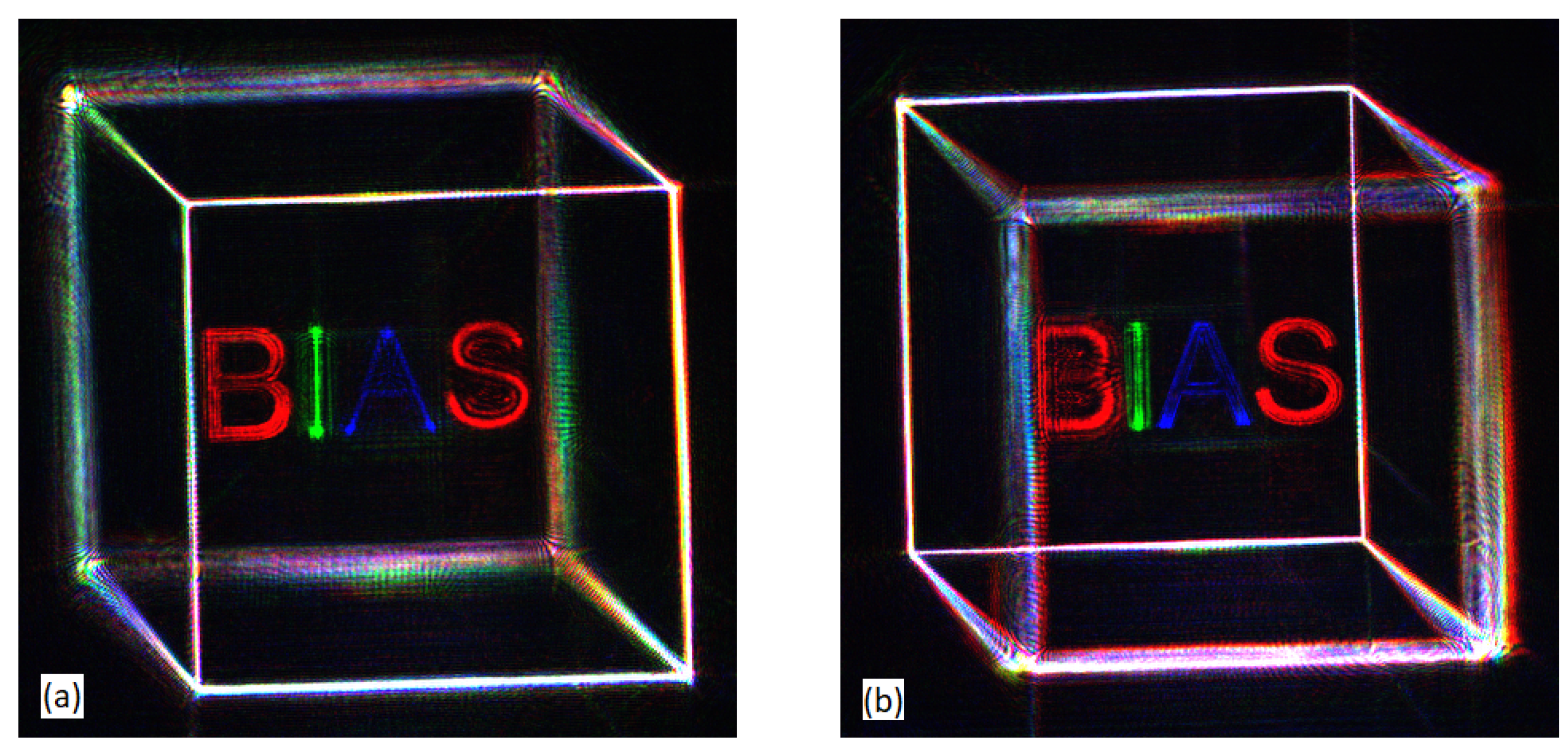
To demonstrate the multicolor display of RELPH-holograms via temporal multiplexing, we present an obliquely oriented wire frame cube of constant intensity along its edges across all three color channels. Its front and rear faces are placed at distances of 150 mm and 130 mm in front of the SLM plane, respectively. Within the wire frame cube, the letters BIAS are displayed in different colors, while being placed in descending distances in the same distance range as above. For each color channel, the 3D scene was sliced into 51 parallel equidistant slices which were propagated and superpositioned into the SLM plane, where the resulting wave field was decomposed into two phase-only wave fields of constant amplitude E 1 and E 2 . As an example, the phase distributions of each color channel for one of the SLMs are displayed in Figure 3.
The wave field was captured by a CCD camera with the lens positioned to focus on either the front or rear faces of the wire frame cube. In Figure 4, the captured 3D scene is shown, where the three images corresponding to the different color channels were recorded in temporal sequence. The image shown in Figure 4a is focused on the front of the 3D scene, with the three color channels combining for a sharp and white front face of the cube, the letter B also being in focus, and the other letters as well as the rear face being increasingly out of focus, as expected. In turn, in Figure 4b, the focus is on the rear side, and the letter S displays the 3D cue depth of field. A constant dim background is present due to the light reflected from inactive areas of the SLMs corresponding to their fill factor [31].

3.2. Spatial Multiplexing

In order to demonstrate a multicolor display of RELPH-generated holograms, we use the wavelengths of 633 nm and 532 nm to demonstrate the concept of simultaneous spatial multiplexing of different colors according to the setup shown in Figure 1b. To define a mutual imaging plane of the separate RELPH setups, the optical path difference that generally exists between the SLM planes of the respective RELPH-setups and the beam-splitter combining the two setups has to be determined. This was done by displaying auxiliary grid lines propagated into depth planes of varying distances from the respective SLM planes until the grid lines from both setups were propagated into the same focal plane. For the subsequent display of 3D scenes, this optical path difference was compensated when calculating the diffraction patterns for the respective setups. The addition of a third color for RGB display would be analogous to this method.
The extent of the displayed 3D scenes is mainly limited by the size of SLM of 15.36 × 8.64 mm, as well as the maximum diffraction angle of the SLM being around 2 when using light in the visible range due to the SLMs’ pixel pitch of 8 µm. With the number of pixels of the SLM ( 1920 × 1080 ) defining a fixed SBP and thus the trade-off between the angle and area of a modulated wave field, we present a simple way to reshape this relationship for a more comfortable viewing experience by magnifying the 3D scene using the two-lens setup shown in Figure 2. The focal length of the lenses L 1 and L 2 are f 1 = 30 mm and f 2 = 250 mm, and the diameter of L 2 is 150 mm, effectively defining the aperture of the magnified scene. The lenses are placed in a distance of d = 340 mm with respect to one another.
To calculate the diffraction patterns, the magnifying setup had to be taken into account, with each 2D slice of the 3D scene being resized and propagated according to Equations (6) and (7). The magnified cube was displayed as a real image laying between 15 mm and 50 mm behind L 2 , with the edges being 35 mm long, and the front and rear sides being 35 mm apart. This corresponds to an unmagnified cube being generated by the SLMs with edges 3.6 mm long between planes laying 32.8 mm and 32.4 mm in front of L 1 .
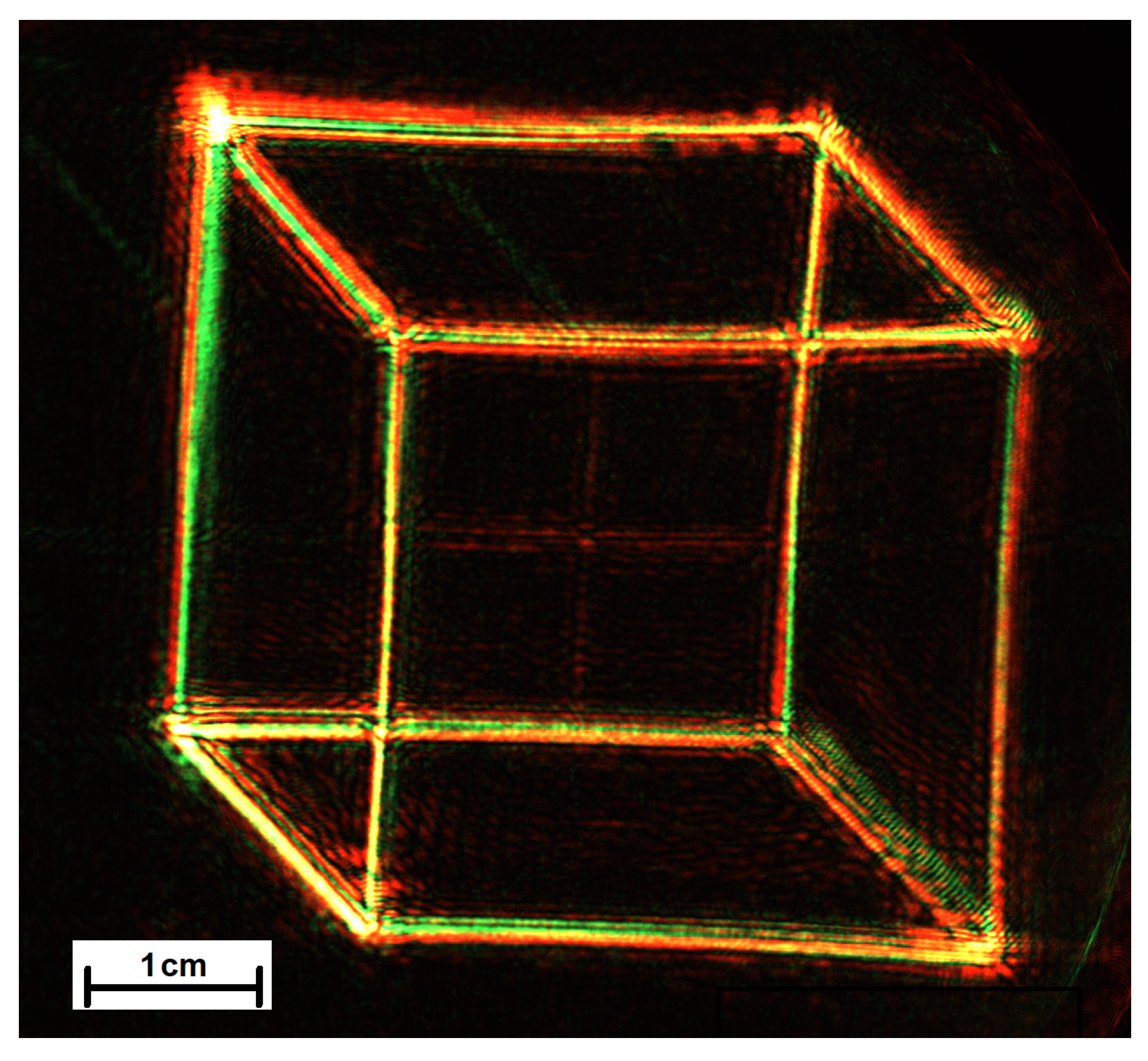
The magnified 3D scene was captured using a color camera with a lens focusing on the front side of the wire frame cube. While in the unmagnified case, a depth impression was apparent when focusing on either faces of the cube, and in Figure 5 no such depth impression is present, as both front and rear sides appear to be equally in focus at the same time. When magnifying 3D scenes, the limited diffraction angle of the SLMs restricts the depth of field, leading to a limited depth perception since the etendue or geometrical extent is conserved. Thus, for magnified wave fields, objects in different depths appear to lie in similar focal planes. To avert this effect, SLMs with a higher space–bandwidth product, containing more and smaller pixels are necessary.
Compared to the 3D scenes generated by temporal multiplexing shown in Figure 4, the magnified reconstruction via spatial multiplexing suffers from further degradation regarding the image quality. The chromatic aberration, which is more pronounced due to the magnifying setup, was at least partially compensated by rescaling of the RELPH-generated holograms and adjusting the propagation distances. Furthermore, the employment of two distinct RELPH setups results in possible alignment errors, and different focusabilities of the RELPH reconstructions, due to different optical paths of the two setups, as well other aberrations, render an additional mutual calibration of the two RELPH setups necessary.

4. Discussion

Referenceless phase holography (RELPH) provides a novel approach for the holographical multicolor display of 3D scenes. With holography of static scenes being well-established, the dynamic holographic display of 3D scenes remains a challenge due to limited space–bandwidth products (SBP) of light modulators. Using phase-only spatial light modulators in Michelson-interferometer-based setups, RELPH reconstructs arbitrary full wave fields (amplitude and phase) while utilizing the SBP of commercially available spatial light modulators in an optimal way. In contrast to classical holography, no zeroth-order diffraction or pseudoscopic images are present for RELPH-generated holograms.
We have presented here two different approaches for the multicolor display of 3D scenes, namely temporal and spatial multiplexing of different colors, superpositioning multiple wave fields in a temporal sequence or by using two separate Michelson-based setups using an additional beam-splitter for superpositioning, demonstrating that the recently introduced referenceless phase holography is a possible candidate for applications such as holographic near-eye 3D displays, medical diagnostics, or industrial design and prototyping. In the case of spatial multiplexing, we presently find a further degradation of the image quality which requires an additional mutual calibration of the RELPH setups for each color for further development. Improvement in the image quality might also be achieved using convolutional neural networks [24] or camera-in-the-loop technology [25].
Currently, a main limitation of holographic 3D displays is the limited SBP of available SLMs. However, for certain potential applications of a RELPH display, it may be suitable to sacrifice available viewing angles for an increased lateral size of the 3D images. For this purpose, we demonstrated a straightforward way to magnify the 3D scene, increasing the overall lateral size to around 6.8 cm but decreasing the viewing angle. However, this procedure resulted in a loss of depth impression, demonstrating the need for SLMs with higher SBP for demanding commercial applications.

Author Contributions

Conceptualization, C.F. and R.B.B.; software, A.F.M. and I.R.; formal analysis and validation, A.F.M.; experimental investigation, A.F.M. and I.R.; writing—original draft preparation, A.F.M.; writing—review and editing, A.F.M., I.R., C.F. and R.B.B.; visualization, A.F.M. and I.R.; supervision, C.F. and R.B.B.; funding acquisition, R.B.B. All authors have read and agreed to the published version of the manuscript.

Funding

This research was funded by Deutsche Forschungsgemeinschaft (DFG) in the framework of the project RELPH 2 grant number 250959575.

Institutional Review Board Statement

Not applicable.

Informed Consent Statement

Not applicable.

Data Availability Statement

The data presented in this study are available on request from the corresponding author.

Acknowledgments

The authors would like to thank C. Kapitza for the technical support.

Conflicts of Interest

The authors declare no conflict of interest. The funders had no role in the design of the study; in the collection, analyses, or interpretation of data; in the writing of the manuscript, or in the decision to publish the results.

Abbreviations

The following abbreviations are used in this manuscript:
RELPHReferenceless phase holography
SLMSpatial light modulator
CCDCharge-coupled device
SBPspace–bandwidth product
BSbeam-splitter

References

  1. Caulfield, H.J.; Leith, E.N.; Denisyuk, Y.N. The Art and Science of Holography; Society of Photo-Optical Instrumentation Engineers (SPIE): Bellingham, WA, USA, 2003. [Google Scholar]
  2. Maimone, A.; Georgiou, A.; Kollin, J.S. Holographic near-eye displays for virtual and augmented reality. ACM Trans. Graph. 2017, 36, 1–16. [Google Scholar] [CrossRef]
  3. Agour, M.; Kreis, T. Experimental investigation of holographic 3D-TV approach. In Proceedings of the 2009 3DTV Conference: The True Vision-Capture, Transmission and Display of 3D Video, Potsdam, Germany, 4–6 May 2009; pp. 1–4. [Google Scholar]
  4. Smalley, D.; Nygaard, E.; Squire, K.; Van Wagoner, J.; Rasmussen, J.; Gneiting, S.; Qaderi, K.; Goodsell, J.; Rogers, W.; Lindsey, M.; et al. A photophoretic-trap volumetric display. Nature 2018, 553, 486–490. [Google Scholar] [CrossRef] [PubMed]
  5. Hirayama, R.; Plasencia, D.M.; Masuda, N.; Subramanian, S. A volumetric display for visual, tactile and audio presentation using acoustic trapping. Nature 2019, 575, 320–323. [Google Scholar] [CrossRef] [PubMed]
  6. Huang, F.C.; Luebke, D.P.; Wetzstein, G. The light field stereoscope. In SIGGRAPH Emerging Technologies; Association for Computing Machinery: Los Angeles, CA, USA, 2015; pp. 1–24. [Google Scholar]
  7. Hua, H.; Javidi, B. A 3D integral imaging optical see-through head-mounted display. Opt. Express 2014, 22, 13484–13491. [Google Scholar] [CrossRef] [PubMed]
  8. Hong, J.; Kim, Y.; Choi, H.J.; Hahn, J.; Park, J.H.; Kim, H.; Min, S.W.; Chen, N.; Lee, B. Three-dimensional display technologies of recent interest: Principles, status, and issues [Invited]. Appl. Opt. 2011, 50, H87–H115. [Google Scholar] [CrossRef] [PubMed] [Green Version]
  9. Kujawinska, M.; Kozacki, T.; Falldorf, C.; Meeser, T.; Hennelly, B.M.; Garbat, P.; Zaperty, W.; Niemelä, M.; Finke, G.; Kowiel, M.; et al. Multiwavefront digital holographic television. Opt. Express 2014, 22, 2324–2336. [Google Scholar] [CrossRef] [PubMed] [Green Version]
  10. Smalley, D.E.; Smithwick, Q.; Bove, V.; Barabas, J.; Jolly, S. Anisotropic leaky-mode modulator for holographic video displays. Nature 2013, 498, 313–317. [Google Scholar] [CrossRef]
  11. Slinger, C.; Cameron, C.; Stanley, M. Computer-generated holography as a generic display technology. Computer 2005, 38, 46–53. [Google Scholar] [CrossRef]
  12. Jia, J.; Chen, J.; Yao, J.; Chu, D. A scalable diffraction-based scanning 3D colour video display as demonstrated by using tiled gratings and a vertical diffuser. Sci. Rep. 2017, 7, 1–9. [Google Scholar]
  13. Agour, M.; Falldorf, C.; von Kopylow, C.; Bergmann, R.B. Speckle reduction in holographic projection using temporal-multiplexing of spatial frequencies. In Proceedings of the 2013 3DTV Vision Beyond Depth (3DTV-CON), Aberdeen, UK, 7–8 October 2013; pp. 1–4. [Google Scholar]
  14. Agour, M.; Falldorf, C.; Bergmann, R.B. Holographic display system for dynamic synthesis of 3D light fields with increased space bandwidth product. Opt. Express 2016, 24, 14393–14405. [Google Scholar] [CrossRef]
  15. Kamau, E.N.; Heine, J.; Falldorf, C.; Bergmann, R.B. Dynamic wave field synthesis: Enabling the generation of field distributions with a large space–bandwidth product. Opt. Express 2015, 23, 28920–28934. [Google Scholar] [CrossRef] [PubMed]
  16. Blanche, P.A.; Bablumian, A.; Voorakaranam, R.; Christenson, C.; Lin, W.; Gu, T.; Flores, D.; Wang, P.; Hsieh, W.Y.; Kathaperumal, M.; et al. Holographic three-dimensional telepresence using large-area photorefractive polymer. Nature 2010, 468, 80–83. [Google Scholar] [CrossRef] [PubMed]
  17. Reichelt, S.; Häussler, R.; Fütterer, G.; Leister, N. Depth cues in human visual perception and their realization in 3D displays. In Three-Dimensional Imaging, Visualization, and Display 2010 and Display Technologies and Applications for Defense, Security, and Avionics IV; International Society for Optics and Photonics (SPIE): Orlando, FL, USA, 2010; Volume 7690, p. 76900B. [Google Scholar]
  18. Haeussler, R.; Gritsai, Y.; Zschau, E.; Missbach, R.; Sahm, H.; Stock, M.; Stolle, H. Large real-time holographic 3D displays: Enabling components and results. Appl. Opt. 2017, 56, F45–F52. [Google Scholar] [CrossRef] [PubMed]
  19. Yang, X.; Song, P.; Zhang, H.; Wang, Q.H. Full-color computer-generated holographic near-eye display based on white light illumination. Opt. Express 2019, 27, 38236–38249. [Google Scholar] [CrossRef] [PubMed]
  20. Kozacki, T.; Chlipala, M. Color holographic display with white light LED source and single phase only SLM. Opt. Express 2016, 24, 2189–2199. [Google Scholar] [CrossRef]
  21. Kozacki, T.; Chlipala, M.; Makowski, P.L. Color Fourier orthoscopic holography with laser capture and an LED display. Opt. Express 2018, 26, 12144–12158. [Google Scholar] [CrossRef]
  22. Kazempourradi, S.; Ulusoy, E.; Urey, H. Full-color computational holographic near-eye display. J. Inf. Disp. 2019, 20, 45–59. [Google Scholar] [CrossRef]
  23. Wang, Y. Color dynamic holographic 3D displays: Approaches and systems. In Digital Holography and Three-Dimensional Imaging; Optical Society of America: JeJu Island, Korea, 2017. [Google Scholar]
  24. Shi, L.; Li, B.; Kim, C.; Kellnhofer, P.; Matusik, W. Towards real-time photorealistic 3D holography with deep neural networks. Nature 2021, 591, 234–239. [Google Scholar] [CrossRef] [PubMed]
  25. Choi, S.; Kim, J.; Peng, Y.; Wetzstein, G. Optimizing image quality for holographic near-eye displays with michelson holography. Optica 2021, 8, 143–146. [Google Scholar] [CrossRef]
  26. Shi, L.; Huang, F.C.; Lopes, W.; Matusik, W.; Luebke, D. Near-eye light field holographic rendering with spherical waves for wide field of view interactive 3d computer graphics. ACM Trans. Graph. 2017, 36, 1–17. [Google Scholar] [CrossRef]
  27. Kreis, T. 3-d display by referenceless phase holography. IEEE Trans. Ind. Inform. 2016, 12, 685–693. [Google Scholar] [CrossRef]
  28. Kreis, T. Referenceless Phase Holography for 3D Imaging. 3D Res. 2017, 8, 1–18. [Google Scholar] [CrossRef]
  29. Schnars, U.; Falldorf, C.; Watson, J.; Jüptner, W. Digital holography. In Digital Holography and Wavefront Sensing; Springer: Berlin/Heidelberg, Germany, 2015; pp. 39–68. [Google Scholar]
  30. Goodman, J.W. Introduction to Fourier Optics; Roberts and Company Publishers: Greenwood Village, CO, USA, 2005. [Google Scholar]
  31. Agour, M.; Falldorf, C.; Von Kopylow, C. Digital pre-filtering approach to improve optically reconstructed wavefields in opto-electronic holography. J. Opt. 2010, 12, 055401. [Google Scholar] [CrossRef]
Figure 1. (a) Schematic representation of the Michelson-based RELPH setup. Light from a laser is expanded, parallelized, and linearly polarized in accordance with the birefringent axis of two phase-only liquid crystal spatial light modulators (SLM), placed after a beam-splitter, in the two interferometer arms of a Michelson setup. The reflected light is modulated by the SLMs to produce wave fields representing arbitrary 3D scenes in imaging planes laying anywhere in front of or behind the SLM plane; (b) Representation of the setup combination used for spatial multiplexing of several wavelengths. For simplicity, only a two-wavelength mixing is shown here. The light of two different wavelengths (shown in green and red, respectively) is modulated by two RELPH setups, identical to the one in (a). The modulated wave fields are superpositioned using the additional beam-splitter BS 3 for a multicolor viewing experience.
Photonics 08 00247 g001
Figure 2. Schematic representation of two objects (red and green) magnified by a two-lens setup, with focal lengths f 1 and f 2 , placed in a distance of d > f 1 + f 2 relative to one another. The original small red and green objects in front of lens L 1 are reconstructed by a RELPH setup into the imaging planes also shown in Figure 1a. The red object is magnified and imaged as a real image in the distance z mag behind the second lens L 2 , while the green one is imaged in front of L 2 as a virtual image. Note that the light converges towards the optical axis and the observer. This fact is important for holograms produced by SLMs with small diffraction angles to reduce the aperture of a potential observing lens L 3 .
Photonics 08 00247 g002
Figure 3. Diffraction patterns of a wire frame cube and the letters BIAS, inscribed into one of the two SLMs for temporal multiplexing of three colors red, 633 nm (a), green, 532 nm (b), and blue, 488 nm (c). Additionally to the diffraction pattern itself being wavelength-dependent due to the propagation in Equation (5), the refractive properties of the SLM are wavelength-dependent, resulting in scaled phase values inscribed into the SLM for varying wavelengths.
Photonics 08 00247 g003
Figure 4. Multicolor 3D scenes displayed by temporal multiplexing of three separate wavelengths (633 nm, 532 nm, and 488 nm), with the three color channels being recorded in temporal sequence. Displayed is a tilted wire frame cube with constant intensity across all three colors, resulting in an approximately uniform white appearance. The edges of the cube are 5 mm long, with the front and rear sides of the cube displayed at 150 mm and 130 mm in front of the SLM plane, respectively. Inside the cube, the letters BIAS are displayed in different colors, laying in four distinct depth planes between 150 mm and 130 mm from the SLM plane. In (a) the recording setup is focused on the front plane of the cube in which the letter B also lies, the rear plane and the other letter appearing out of focus, displaying a distinct depth impression. Instead, in (b) the rear plane and the letter S are in focus.
Photonics 08 00247 g004
Figure 5. Magnified multicolor 3D scene displayed via spatial multiplexing of wave field generated by two separate RELPH setups, using lasers with wavelengths of 633 nm and 532 nm, respectively. Due to the limited diffraction angle of the SLMs in use, the depth perception for the magnified 3D scene is severely limited. Accordingly, the front and rear faces of the cube separated by 35 mm appear to lie in the same focus plane.
Photonics 08 00247 g005
Publisher’s Note: MDPI stays neutral with regard to jurisdictional claims in published maps and institutional affiliations.