Abstract
The propagation of many kinds of structured light beams in uniaxial crystal has been investigated. However, the investigation of the evolution of these structured light beams after the uniaxial crystal is lacking. In this paper, an evolution formula of a light beam after passing through a uniaxial crystal is derived. Based on the formula, controlling the autofocusing of a circular Airy vortex beam (CAVB) via a uniaxial crystal is studied. It is found that a uniaxial crystal can prolong the focal length of the autofocusing. By changing the crystal length, the relative weight of the left- and right-hand circular polarization components and the relative value between the orbital and spin angular momentum densities of the beam’s focal plane can be adjusted flexibly. In addition, other optical elements can be inserted between the crystal and the focus to further adjust the focal plane field distribution. The influences of inserting x- and y-polarization polarizers on the intensity distribution are calculated as examples.
1. Introduction
A circular Airy beam (CAB) is a significant type of beam due to its self-accelerating, self-healing, and abrupt autofocusing properties [1,2,3,4,5]. Abrupt autofocusing means that a CAB maintains low intensity first, then immediately focuses spontaneously on the focal plane to enhance its intensity significantly. This leads to the CAB having great application value in optical manipulation [6], biomedicine [7], laser processing [8], and other fields. A vortex beam, a light beam with a spiral phase, is another kind of novel light beam. It is well known that the vortex beam carries orbital angular momentum (OAM), which can be transferred to nanoparticles to cause rotation [9,10,11]. Hence, the vortex beam is also very meaningful in optical manipulation. A circular Airy vortex beam (CAVB) is a CAB possessing a spiral phase. It has both the excellent properties of the CAB and vortex beam. Therefore, the CAVB has drawn wide attention from researchers in recent years.
To promote the flexible applications of CAVB in many fields, the investigation of controlling the propagation characteristics of CAVB is meaningful and important. There are many works about the propagation of CAVB and modulated CAVB in crystal [12] and free space [13] reported. As a typical anisotropic medium, uniaxial crystals play an important role in light modulation and control [14,15,16]. In recent years, the propagation of many kinds of light beams in uniaxial crystals has been investigated. For example, with the inspiration of the vectorial theory of light propagating in uniaxial crystal [17], the propagation of an Airy beam [18], quadratic-power-exponent-phase vortex beam [19], CAB [20,21], Airyprime beam [22], Airy vortex beam [23] and CAVB [12] in uniaxial crystal were investigated.
Though these previous investigations have provided an effective way to control light beam evolution via uniaxial crystal, they focused only on the propagation when the light is inside the crystal and the light evolution after the crystal was not investigated. This limits the application of the modulated beams in some practical scenarios. For example, in the scenario of micromanipulation, we use the focal point of a CAB to trap and manipulate a microparticle, which is impossible if the focal point is inside a uniaxial crystal. Therefore, the topic really worth studying is the controlling effect of a uniaxial crystal on the abrupt autofocusing when the focal point is outside the uniaxial crystal rather than inside it. In this case, the propagation evolution of the light beam after the uniaxial crystal needs to be studied. From this point of view, it is important and necessary to derive the a formula that describes the light beam evolution after passing through the uniaxial crystal.
Therefore, in this paper, we first derive the evolution formula of a light beam after passing through a uniaxial crystal. Then, based on the evolution formula, we investigate the controlling of the abrupt autofocusing of the CAVB via uniaxial crystal when the focal point is outside the uniaxial crystal. A schematic diagram is shown in Figure 1, in which the red lines with arrows represent the trajectory of the energy flow of the CAVB during the propagation.
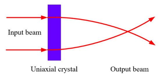
Figure 1.
The schematic diagram of controlling the abrupt autofocusing of CAVB via uniaxial crystal when the focal point is outside the uniaxial crystal.
2. Theory
When a monochromatic light E(r,t) = E(r)exp(−iωt) propagates in a uniaxial crystal, the electric field obeys the following:
where k0 = ω/c is the wave vector in vacuum and represents the relative dielectric tensor. In this study, we assume that the z axis of the Cartesian coordinate system coincides with the optical axis of the uniaxial crystal. In this case, the relative dielectric tensor can be written as , where no and ne represent the ordinary and extraordinary refractive indices of the crystal, respectively.
According to angular spectrum theory, the light wave propagating in the crystal, i.e., the fundamental solutions of Equation (1), is the superposition of a series of plane waves, which can be divided into two sets, i.e., ordinary waves and extraordinary waves. Considering the input plane of the uniaxial crystal as z = 0 plane, the angular spectrum of the ordinary waves and the extraordinary waves in the crystal can be respectively expressed as [17]
where , and with , , and being the Cartesian component electric field expression of the input light beam at the z = 0 plane.
Considering the length of the crystal is L, the angular spectrum of the ordinary waves and the extraordinary waves at the output plane of the crystal are and . According to the continuity conditions, the transverse wave vector remains constant as the plane waves pass through the interface between the crystal and free space, while the longitudinal wave vectors of both the ordinary waves and the extraordinary waves become . Hence, at arbitrary plane, i.e., the free space region after the crystal, the angular spectrum of the ordinary waves and the extraordinary waves can be expressed as
It should be noted that in Equation (3) the -dependent amplitude reflection coefficient at the interface has been ignored. This is reasonable under the condition of paraxial approximation when a thin antireflection film is coated on the interface.
With the angular spectrum expressions of the ordinary waves and extraordinary waves, according to the angular spectrum theory, the light field at the arbitrary z plane can be calculated via When the light is in the crystal, i.e., , this expression of the light field has been derived in [15,17]. The result is given by
where n is topological charge, is azimuth angle, and are respective the unit vectors of left-hand circular polarization (LHCP) and right-hand circular polarization (RHCP) components, and
where Jn(·) denotes the nth-order Bessel function, and
where and are the LHCP and RHCP components of the incident light field at z = 0 plane.
Performing similar derivations as [15,17], we obtain that the light field after the crystal, i.e., , is
where
It can be verified that Equation (7) can transform into Equation (4) when , and when , i.e., there is no uniaxial crystal on the propagation path of the light beam, and Equations (7) and (8) become and . In this case, the expressions of and are the Hankel transform pair of a beam propagating in free space.
Equations (4) and (7) are the propagation evolution formulae in and after a uniaxial crystal applicable to an arbitrary paraxial light beam, such as a CAB [20,21] and Airy–Gauss beam [22]. With them, the controlling effect of a uniaxial crystal on the light evolution after passing through the crystal can be investigated by numerical calculation. This is the core idea of this paper. In the following, choosing a first-order CAVB with LHCP as the sample input light beam, we calculate its propagation evolution according to Equations (4) and (7). This study will provide some meaningful insights to the regulating of the autofocusing of CAVB via uniaxial crystal. The initial electric field of the first-order CAVB with LHCP is given by
where C is a constant, and Ai, r0, w and a are the Airy function, initial radius, radially scaled coefficient, and decay parameter of the CAVB, respectively. In this case, only is nonzero, which is:
According to our previous work [24], the approximate expression of Equation (10) is:
Substituting Equation (11) into Equations (4) and (7), we can now investigate the evolution of the CAVB during the propagation via numerical calculation.
3. Results and Discussion
We first calculate the intensity distributions of the CAVB under different lengths of the uniaxial crystal. In the calculation, r0 = 0.3 mm, w = 14 μm, a = 0.1, C = 1 V/mm, λ = 632.8 nm, no = 2.616, ne = 2.903 are used (unless otherwise specified, these parameters are used throughout the paper). Figure 2 shows the calculated normalized intensity distributions of the CAVB during propagation under different crystal lengths, in which Figure 2a–d are the results under L = 0 mm, 10 mm, 20 mm and 30 mm, respectively. The white dotted lines are the output planes of the crystals with different lengths, and the white arrows show the location of the focus. Clearly, a uniaxial crystal can prolong the focal length of the CAVB autofocusing. The underlying physical mechanism of this phenomenon can be explained as follows. For the ordinary and extraordinary plane waves with transverse wave vector , the transverse wave vectors of the waves in the uniaxial crystal and after the uniaxial crystal remain unchanged (guaranteed by the continuity conditions when the plane waves pass through the interface between the crystal and free space), while the longitudinal wave vectors change. The longitudinal wave vector components of the ordinary and extraordinary waves are, respectively, and when the waves are in the uniaxial crystal, while after the uniaxial crystal, the longitudinal wave vector components of them become unified to be . Hence, in the crystal, the polar angle of the wave vector of the ordinary wave is and the polar angle of the wave vector of the extraordinary wave is , and after the crystal, the polar angle of the wave vector of the ordinary and extraordinary waves become unified to be . Since both and are greater than , is greater than and , implying that the CAVB focuses faster in free space than in the crystal. This is evident from the light beam’s autofocusing trajectory, which focuses slowly in front of the output plane of the crystal and rapidly after the crystal, as shown in Figure 2. Hence, a uniaxial crystal can be used to adjust the location of the CAVB focus.
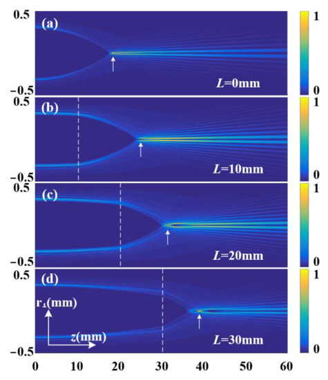
Figure 2.
Normalized intensity distributions during propagation under different crystal lengths. (a–d) Results for L = 0 mm, 10 mm, 20 mm and 30 mm, respectively. The white dotted lines are the output planes of the crystals, and the white arrows show the location of the focus.
Here, it should be noted that the above analysis applies not only to the uniaxial crystal but also to isotropic medium. As long as the refraction index n of an isotropic medium is larger than 1, the longitudinal wave vector components in the medium is larger than that in free space so that the beam autofocuses more slowly in the medium. Therefore, an isotropic medium can also prolong the focal length of the CAVB autofocusing. It is well known that the most important impact of the anisotropy of a uniaxial crystal on a light beam passing through it is inducing spin–orbit coupling. As such, to find the novel effect specifically brought by the anisotropy, we should investigate the evolution of the LHCP and RHCP components of the CAVB and the evolution of the corresponding angular momentum (AM).
For this, introducing and to represent the LHCP and RHCP components of and to indicate the focal plane, we calculate the intensity distributions of (blue line) and (red line) on axis. The calculated results are shown in Figure 3. In the figure, the intensity distributions are normalized by max[] and Figure 3a–d are the results under L = 0 mm, 10 mm, 20 mm and 30 mm, respectively. The results show that when L = 0 mm, i.e., there is no uniaxial crystal on the propagation path of the beam and the RHCP component is zero, while when L ≠ 0 mm, i.e., there exists a uniaxial crystal on the propagation path, the RHCP component is nonzero. This is due to the spin–orbit coupling of the light beam in the uniaxial crystal. It can be seen that the length of the crystal can significantly affect the efficiency of the spin–orbit coupling. This is consistent with the result of Equations (4) and (5), from which one can obtain that the expression of the RHCP component at the output plane of the uniaxial crystal is with implying that the energy of the RHCP component converting from the LHCP component by spin–orbit coupling is crystal length L-dependent via the item . This is consistent with the result of [25], so not a new discovery here. Since the expression of is complex, the analytic expression of cannot be obtained. Therefore, we cannot obtain a simple analytical expression of the conversion efficiency, which should be calculated numerically. In fact, the analytical expression for conversion efficiency can be obtained only in a few cases where the incident light is a Gaussian or Bessel beam [25]. It is found that when L = 10 mm, most of the input light is converted from LHCP to RHCP, while when L = 20 mm, the efficiency of the input LHCP converting to RHCP becomes lower than the conversion efficiency when L = 10 mm, and when L = 30 mm, the conversion efficiency becomes even lower. This is due to the conversion of the LHCP and RHCP components back and forth during the propagation as the crystal length increases. In practical applications, the relative weight of the LHCP and RHCP components of the CAVB focus can be adjusted flexibly by using different crystal lengths.
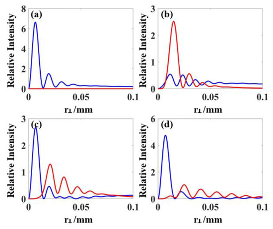
Figure 3.
The relative intensity |E+(r⊥, φ, zf)|2/max [|E(r⊥, φ, 0)|2] (blue line) and |E−(r⊥, φ, zf) |2/max [|E(r⊥, φ, 0)|2] (red line) on the r⊥ axis under (a) L = 0 mm, (b) L = 10 mm, (c) L = 20 mm and (d) L = 30 mm.
We further investigate the control of the uniaxial crystal on the AM of the CAVB. It is well known that the AM density of a light field can be expressed as jz = sz + lz, with being the OAM density, being the spin AM (SAM) density, where ε0 is vacuum permittivity, and ω is angular frequency. Therefore, in the case investigated here, on the focal plane, we have and . The calculated focal plane AM density distribution on the r⊥ axis under different crystal lengths is shown in Figure 4, in which the results are relative to ε0/2ω. It is found that the relative values between the OAM and SAM densities can be adjusted by changing the crystal length. As is well known, the AM density is an important parameter in optical manipulation, which determines the orbital rotation and spin of the particle trapped at the focus. When L = 0 mm, both the OAM and SAM densities are positive, hence a particle trapped at the focus will be driven to spin and orbitally rotate in a counterclockwise direction. When L = 10 mm, the OAM density is still positive, hence the particle trapped at the focus will still orbitally rotate in counterclockwise direction, while the SAM density becomes negative, and hence the particle trapped at the focus will be driven to spin in a clockwise direction. When L = 20 mm and 30 mm, both the OAM and SAM densities become positive again; however, the relative weight between them is different from the case of L = 0 mm, hence it will drive the trapped particle to spin and orbitally rotate with speed different from the case of L = 0 mm. Therefore, in practical applications, our results can be used to control the rotation direction and the relative rotation speed between the orbital rotation and spin of the trapped particle to promote the flexible applications of the CAVB in optical manipulation.
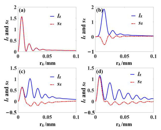
Figure 4.
The focal plane AM density distributions on r⊥ axis under (a) L = 0 mm, (b) 10 mm, (c) 20 mm and (d) 30 mm. The results are relative to ε0/2ω.
Moreover, as the focal point is outside the crystal, it is permissible to insert other optical elements, such as polarizer and wave plate, between the crystal and the focus to further adjust the field distribution of the focal plane. This will greatly increase the flexibility of the light field regulation. Considering x- and y-polarization polarizers, which can extract the corresponding polarization light components, as examples, we calculate the normalized intensity distributions of the x-polarized component, the y-polarized component and the total field of the focal plane under different crystal lengths. The results are shown in Figure 5. It can be seen that different focal intensity patterns can be obtained by varying the crystal length and using different polarizers.
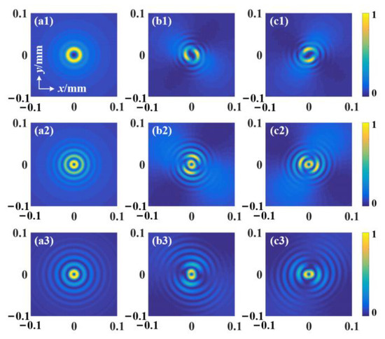
Figure 5.
Normalized intensity distributions on the focal plane under different crystal lengths. The first, second, and third columns correspond to the intensity distributions of the total field, the x-polarized component, and the y-polarized component, respectively. The first (a1,b1,c1), second (a2,b2,c2), and third (a3,b3,c3) rows correspond to L = 10 mm, 20 mm and 30 mm, respectively.
4. Conclusions
In summary, in this paper, a formula describing the evolution of a light beam passing through a uniaxial crystal was derived, based on which the control of CAVB autofocusing via uniaxial crystal was studied. It was found that a uniaxial crystal can prolong the focal length of the autofocusing. This can change the position of the focus and hence be used to change the trapping position of a particle in optical manipulation. It was also found that by changing the crystal length, the relative weight of the left- and right-hand circular polarization components and the relative value between the orbital and spin angular momentum densities of the beam’s focal plane can be adjusted flexibly. It can be used to control the rotation direction and the relative rotation speed between the orbital rotation and spin of the trapped particle in optical manipulation. In addition, as the focal point is outside the crystal, other optical elements can be inserted between the crystal and the focus to further adjust the focal plane field distribution. The influences of inserting x- and y-polarization polarizers on the intensity distribution were calculated as examples. It was found that different focal intensity patterns can be obtained by varying the crystal length and using different polarizers. This work can offer a good theoretical reference for controlling the CAVB, which should be useful for the flexible manipulation of this kind of novel light beam as well as the design of related optical systems to promote its practical applications.
Author Contributions
Conceptualization, H.L. and J.Z.; investigation, H.L., J.Z., H.P. and J.X.; writing—original draft preparation, H.L., J.Z., H.P. and J.X.; writing—review and editing, R.X. and L.Y.; funding acquisition, H.L., R.X. and L.Y. All authors have read and agreed to the published version of the manuscript.
Funding
This research was funded by the National Natural Science Foundations of China (62065006), Natural Science Foundations of Guangxi (2020GXNSFBA159059), Guangxi Key Laboratory Project of Optoelectronic Information Processing (GD20103), Guangxi Key Laboratory Project of Automatic Detection Technology and Instrument (YQ20103), Innovation Project of Guangxi Graduate Education (YCSW2022297), Innovation Project of GUET Graduate Education (2021YCXS130), and Innovation Project of College Student (S202110595234).
Data Availability Statement
Not applicable.
Conflicts of Interest
The authors declare no conflict of interest.
References
- Efremidis, N.K.; Christodoulides, D.N. Abruptly autofocusing waves. Opt. Lett. 2010, 35, 4045–4047. [Google Scholar] [CrossRef] [PubMed]
- Siviloglou, G.A.; Christodoulides, D.N. Accelerating finite energy Airy beams. Opt. Lett. 2007, 32, 979–981. [Google Scholar] [CrossRef] [PubMed]
- Papazoglou, D.G.; Efremidis, N.K.; Christodoulides, D.N.; Tzortzakis, S. Observation of abruptly autofocusing waves. Opt. Lett. 2007, 36, 1842–1844. [Google Scholar] [CrossRef] [PubMed]
- Broky, J.; Siviloglou, G.A.; Dogariu, A.; Christodoulides, D.N. Self-healing properties of optical Airy beams. Opt. Express 2008, 16, 12880–12891. [Google Scholar] [CrossRef] [PubMed]
- Liu, S.; Wang, M.; Li, P.; Zhang, P.; Zhao, J. Abrupt polarization transition of vector autofocusing Airy beams. Opt. Lett. 2013, 38, 2416–2418. [Google Scholar] [CrossRef]
- Zhang, P.; Prakash, J.; Zhang, Z.; Mills, M.S.; Efremidis, N.K.; Christodoulides, D.N.; Chen, Z. Trapping and guiding microparticles with morphing autofocusing Airy beams. Opt. Lett. 2011, 36, 2883–2885. [Google Scholar] [CrossRef]
- Dasgupta, R.; Ahlawat, S.; Verma, R.S.; Gupta, P.K. Optical orientation and rotation of trapped red blood cells with Laguerre-Gaussian mode. Opt. Express 2011, 19, 7680–7688. [Google Scholar] [CrossRef]
- Panagiotopoulos, P.; Papazoglou, D.G.; Couairon, A.; Tzortzakis, S. Sharply autofocused ring-Airy beams transforming into on-linear intense light bullets. Nat. Commun. 2013, 4, 2622. [Google Scholar] [CrossRef]
- Allen, L.; Beijersbergen, M.W.; Spreeuw, R.J.C.; Woerdman, J.P. Orbital angular momentum of light and the transformation of Laguerre-Gaussian laser modes. Phys. Rev. A 1992, 45, 8185–8189. [Google Scholar] [CrossRef]
- Allen, L.; Padgett, M.J.; Babiker, M. The orbital angular momentum of light. Prog. Opt. 1999, 39, 291. [Google Scholar]
- Volke-Sepulveda, K.; Garces-Chavez, V.; Chavez-Cerda, S.; Arlt, J.; Dholakia, K. Orbital angular momentum of a high-order Bessel light beam. J. Opt. 2002, B4, S82. [Google Scholar] [CrossRef]
- Zhang, Y.; Li, P.; Liu, S.; Han, L.; Cheng, H.; Zhao, J. Manipulating spin-dependent splitting of vector abruptly autofocusing beam by encoding cosine-azimuthal variant phases. Opt. Express 2016, 24, 28409. [Google Scholar] [CrossRef] [PubMed]
- Zheng, G.; Wu, Q.; He, T.; Zhang, X. Propagation Characteristics of Circular Airy Vortex Beams in a Uniaxial Crystal along the Optical Axis. Micromachines 2022, 13, 1006. [Google Scholar] [CrossRef] [PubMed]
- Ciattoni, A.; Cincotti, G.; Palma, C. Propagation of cylindrically symmetric fields in uniaxial crystals. J. Opt. Soc. Am. A 2002, 19, 792–796. [Google Scholar] [CrossRef] [PubMed]
- Ciattoni, A.; Cincotti, G.; Palma, C. Circularly polarized beams and vortex generation in uniaxial media. J. Opt. Soc. Am. A 2003, 20, 163–171. [Google Scholar] [CrossRef] [PubMed]
- Volyar, A.V.; Fadeeva, T.A. Generation of singular beams in uniaxial crystals. Opt. Spectrosc. 2003, 94, 235–244. [Google Scholar] [CrossRef]
- Ciattoni, A.; Crosignani, B.; Porto, P.D. Vectorial theory of propagation in uniaxially anisotropic media. J. Opt. Soc. Am. A 2001, 18, 1656–1661. [Google Scholar] [CrossRef]
- Zhou, G.Q.; Chen, R.P.; Chu, X.X. Propagation of Airy beams in uniaxial crystals orthogonal to the optical axis. Opt. Express 2012, 20, 2196–2205. [Google Scholar] [CrossRef]
- Liu, H.Q.; Deng, S.J.; Deng, H.C.; Xu, R.H.; Yang, H.Y.; Teng, C.X.; Zhang, L.; Chen, M.; Yuan, L.B. Spin-orbital coupling of quadratic-power-exponent-phase vortex beam propagating in a uniaxial crystal. Opt. Express 2020, 28, 216–225. [Google Scholar] [CrossRef]
- Zheng, G.; Xu, S.; Wu, Q.; Wang, Q.; Ouyang, Z. Electro-optical coupling of a circular Airy beam in a uniaxial crystal. Opt. Express 2017, 25, 14654–14667. [Google Scholar] [CrossRef]
- Zheng, G.; Deng, X.; Xu, S.; Wu, Q. Propagation dynamics of a circular Airy beam in a uniaxial crystal. Appl. Opt. 2017, 56, 2444–2448. [Google Scholar] [CrossRef]
- Bayraktar, M. Propagation of Airyprime beam in uniaxial crystal orthogonal to propagation axis. Optik 2021, 228, 166183. [Google Scholar] [CrossRef]
- Deng, D.M.; Chen, C.D.; Zhao, X.; Li, H.G. Propagation of an Airy vortex beam in uniaxial crystals. Appl. Phys. B 2013, 110, 433–436. [Google Scholar] [CrossRef]
- Liu, H.Q.; Pu, H.L.; Zhang, J.W.; Jiao, Y.H.; Xu, R.H.; Yang, H.Y.; Yuan, L.B. Investigating the propagation characteristics of modulated circular Airy vortex beam in free space via angular spectrum method. Opt. Commun. 2022, 529, 129087. [Google Scholar] [CrossRef]
- Ling, X.; Luo, H.; Guan, F.; Zhou, X.; Luo, H.; Zhou, L. Vortex generation in the spin-orbit interaction of a light beam propagating inside a uniaxial medium: Origin and efficiency. Opt. Express 2020, 28, 27258. [Google Scholar] [CrossRef]


Publisher’s Note: MDPI stays neutral with regard to jurisdictional claims in published maps and institutional affiliations. |
© 2022 by the authors. Licensee MDPI, Basel, Switzerland. This article is an open access article distributed under the terms and conditions of the Creative Commons Attribution (CC BY) license (https://creativecommons.org/licenses/by/4.0/).