1. Introduction
The guided-mode resonance (GMR) effect in a periodic dielectric waveguide has been widely studied and applied to various optical devices. GMR devices utilize a periodic grating to couple incident light to the waveguide structure. When the diffraction wave is phase-matched to a leaky mode, GMR devices can produce total reflection or transmission peaks [
1]. Because this matching condition is highly sensitive to the refractive index (RI) of material on the GMR grating’s surface, GMR devices based on resonance wavelength shift detection have been used as biosensors [
2,
3]. Additionally, the phase of GMR devices has been reported to change abruptly near the resonance condition [
4]. An optical retarder based on GMR has been proposed, and a phase shift of π at the operating wavelength was achieved [
5]. Using the dramatic phase-change near resonance, many phase-based interferometric sensing approaches have been demonstrated. In our previous study, a transmitted-type GMR sensor based on phase detection was proposed using an electro-optic (EO) heterodyne interferometer [
6]. The phase curves of two orthogonally polarized components (
p- and
s-polarized) were plotted against various incident angles. Subsequently, the same sensor, but with the use of a phase-shift interferometer, was reported [
7]. In both approaches, the GMR sensor is rotated to a resonance incident angle to optimize the phase-detection sensitivity and the analyzer can be tuned to further enhance detection sensitivity. In this transmitted-type configuration, the incident light passes through the GMR sensor. When the GMR sensor is rotated, the direction of the transmitted light is maintained and the position of the light-receiving device can be fixed at the same position. This results in a simple and compact optical phase-detection system. Conversely, in a reflection-type configuration, when the GMR device is rotated to be a resonant incident, the direction of the reflected light changes, and the position of the light-receiving device must be changed accordingly. This complicates the phase-detection system because it requires a Δ-2
θ motorized rotation stage for tracking the reflected light. Additionally, in some sensing applications, the reflection-type configuration is required to prevent the incident light from passing through the sample on the GMR sensor, as this may result in unexpected effects in the tested samples.
Recently, a reflection-type common-path interferometer based on a Wollaston prism was developed, and a GMR device was designed with various grating pitches to ensure that the resonance occurred at normal incidence [
8]. Due to the common-path interferometer, this system was not sensitive to environmental noise and achieved a low detection limit. Because the resonance condition of a GMR device can also be achieved by changing the azimuth angle, GMR filters under conical mounting have been studied [
9,
10]. Based on this concept, a GMR sensor with reflection-type phase detection using a Mach–Zehnder interferometer was proposed to maintain the direction of the reflected light and achieve improved resonance by altering the azimuth angle of the GMR device [
11]. In this approach, resonance was attained by rotating the azimuth angle to be a band-pass filter with a center wavelength similar to a He-Ne laser, and the phase-detection sensitivity was compared under resonance and non-resonance conditions. However, the phase properties of scanned azimuth angles for different incident angles were not investigated in their study. In this paper, details of the reflection-type GMR sensor based on azimuthal rotation are reported. The azimuth angle was scanned at various incident angles to construct phase curves, which were numerically studied, and the experimental results obtained using an EO heterodyne interferometer are presented. Furthermore, the phase-detection sensitivity was enhanced by rotating the analyzer in the EO heterodyne interferometer, and the measurement results of a GMR gas sensor are reported.
2. Simulation of the Guided-Mode Resonance Device
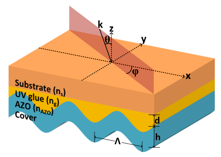
A schematic of the GMR device structure under conical mounting is shown in
Figure 1. Its structure comprises a one-dimensional (1D) sinusoidal UV glue grating imprinted on a glass substrate and a waveguide layer formed of over-coated, aluminum-doped zinc oxide (AZO) thin film. Its fabrication was explored in a previous study [
6]. The grating pitch is defined by the period
Λ along the
x-axis. Polarized light is obliquely incident on the back-side substrate of the GMR device. For conical mounting, the incident wave vector k is a function of both the angle of incidence
θ and the azimuth angle
φ. The conically diffracted wave vector km can be represented by the
mth-order diffraction component given as in [
9]:
where
kx,m, and
ky,m are the components along the x- and y-axes, respectively. For 1D-GMR,
kx,m, and
ky,m can be expressed as:
Resonance can occur when the propagation constant in the leaky waveguide is equal to the longitudinal component of the m-th order diffracted wave vector km. Thus, the phase matching of the diffracted wave and the leaky mode of the waveguide can be achieved by rotating the azimuth angle. The properties of GMR in response to its incident and azimuth angles were verified utilizing commercial software (Rsoft, DiffractMOD) based on the rigorous coupled-wave analysis (RCWA) method.
In the simulations, the refractive indices (RIs) of the glass substrate, UV glue grating, and AZO film were
ns = 1.515,
ng = 1.475, and
nAZO = 1.79, respectively. The grating period Λ was 555 nm, corresponding to a commercially available holographic grating with 1800 lines/mm, and the modulation depth of the UV glue grating was 75 nm, based on an atomic force microscope (AFM) measurement result. An AZO film with a thickness of 275 nm was used as a high-RI waveguide and air (
n = 1.0) was used as the superstrate. A He-Ne laser with a wavelength of 632.8nm was incident on the substrate at an angle of
θ, and the effect of the change in incident angle on the zero-order reflection was first analyzed for both
p- and
s-polarization. The reflectance maps of the GMR device are shown in
Figure 2. The dark blue area represents regions with low reflectivity, whereas the red area represents regions with high reflectivity. The azimuth angle varies from −45° to 45° for selected incident angles ranging from 28° to 33°.
Figure 2a,b illustrate the reflectivity maps of the GMR device for
p- and
s-polarized light, respectively. When the incident angle was in the range 28°–31°, only
p-polarization exhibited resonance, whereas
s-polarization could be used as a reference in the heterodyne interferometer. In this experiment, the incident angle was set between 28° and 31°, and then the azimuth angle was rotated to obtain the phase difference between
p- and
s-polarization. In addition, the reflectance pattern in
Figure 2a can also be found in
Figure 2b with a weak reflectance and vice versa. This reveals a coupling between the TE and TM modes of the grating waveguide.
Plots of the reflectivity versus the azimuth angle for three different incident angles, 29.5°, 30.0°, and 30.5°, are shown in
Figure 3a. As the incident angle increased, the resonant azimuth angle also increased, and the resonant angle width decreased, as shown in
Figure 2. Weak resonances were observed for s-polarization. The phase response of the reflected light versus the azimuth angle for different incident angles is shown in
Figure 3b. The
p-polarization phase curves changed dramatically, corresponding to the resonance peak shown in
Figure 2a. On the other hand, the s-polarization phase curves exhibited only small changes and could be used as a reference in the heterodyne interferometer. Plots of the phase differences between the
s- and
p-polarization components are shown in
Figure 3c.
3. Experimental Results
The GMR device was fabricated using the nanoimprinting process, and details of this process can be found in the previous study [
6]. Instead of coating titanium oxide (TiO2), an AZO film was used in this study because of the convenience of the coating machine. The AFM surface morphology of the fabricated GMR device is shown in
Figure 4a. The GMR device, equipped with a gas chamber and mounted on a rotation stage to scan the azimuth angle, is shown in
Figure 4b. Inlet and outlet tubes were used to control the gas flow inside the chamber. A schematic of the reflection-type, phase difference detection system based on the EO heterodyne interferometer is shown in
Figure 4c. Details of the EO heterodyne interferometer also can be found in the previous study [
6]. In this setup, a lock-in amplifier was used to record the interference signal intensity, as well as the phase difference between the interference signal and reference signal from the signal generator to drive the EO modulator (EOM) with a frequency of 100 Hz. The phase reading value was equal to the phase difference between the
s- and
p-polarization components.
In the first experiment, the EOM and the analyzer were removed from the interferometer, and an optical power detector (Thorlabs PM100) was used in place of the photodetector. The reflectance curves of the scanning azimuth angles for different incident angles were obtained to validate the simulation results. The measured reflectivity of the GMR sensor for
p- and
s-polarization is shown in
Figure 5a. The results reveal that only
p-polarized lights produce peaks at the resonance azimuth angles, and when the incident angle increases, the resonance azimuth angle also increases. This is consistent with the simulation results shown in
Figure 3a. However, it seems that the resonance angles, widths, and three peak values of the measured results are not the same as the simulation results. These may be due to the nonuniform grating structure, and the probing light position on the device may change during scanning the azimuth angle, whereas these results would not affect the phase measurement. Subsequently, all the removed components were installed as the set-up shown in
Figure 4c, and this system was used to measure the phase difference responses of scanned azimuth angles with three different incident angles. The results are shown in
Figure 5b, which roughly agree with the simulation results, as shown in
Figure 3c. The increases in the ends of the phase curves may also be due to the light probing position change during the scanning of the azimuth angle.
In the second experiment, the GMR device was used as a gas sensor. Before performing the sensing measurement, tunable reflected phase-detection sensitivity was demonstrated. In the EO heterodyne interferometer, the phase-detection sensitivity can be tuned by rotating the analyzer. In this experiment, the incident angle was set at 31.7°, and the measurement results of the lock-in amplitude and phase curves versus the azimuth angle for three analyzer angles (45°, 47°, and 49°) are shown in
Figure 6a,b, respectively. This reveals that, near the resonance angle, the phase slope increases when the lock-in amplitude decreases. Rotating the analyzer can tune the passing-through light amplitude ratio between
s- and
p-polarization components, and hence change the interference of light modulation intensity on the photodetector. A small lock-in amplitude reading means less modulation of the light intensity. The decrease in modulation can enhance phase change; however, the modulation strength cannot be tuned too small and must satisfy an acceptable signal-to-noise ratio (SNR). Consequently, the analyzer was set to 49° to obtain an acceptable SNR; this obtained the steepest slope on the phase curve, and hence the highest sensitivity. According to the results in
Figure 6b, the azimuth angle was rotated to 20.45° in the EO heterodyne interferometer.
Subsequently, a helium (He) gas was injected into the chamber to replace the air on the GMR sensor surface. The RIs of air and helium are approximately 1.000276 (for dry air at 15 °C and 101,325 Pa with 450 ppm CO
2 content) and 1.000035, respectively, at a wavelength of 680 nm [
12]. The time evolution results of the phase curve are shown in
Figure 6c. In this experiment, He gas was continuously injected from t = 60 to 120 s. The measured phase decreased at the moment of injection because of the decrease in RI on the GMR sensor surface. The phase then increased as the He gas leaked out. Because this system did not maintain the same temperature in the chamber during the measurement, some small variations in the resulting curve were observed. The phase change during the He injection was approximately 9°, and the RI change Δ
n = 2.41 × 10
−4 RIU. Consequently, in this measurement, the proposed system achieved a detection sensitivity of 3.73 × 10
4 deg./RIU. The fluctuation of phase may be caused by thermal and environment noise. However, this value may be further improved by increasing the time constant of the lock-in amplifier. This may require more time to complete the measurement. Assuming that the statistical error phase of the lock-in amplifier was 0.01°, its detection limit was 2.68 × 10
−7 RIU.

