Article

Intensity-Averaged Double Three-Step Phase-Shifting Algorithm with Color-Encoded Fringe Projection

1
College of Engineering, Anhui Agricultural University, Hefei 230036, China
2
Department of Opto-Electronics, Sichuan University, Chengdu 610065, China
*
Author to whom correspondence should be addressed.
Photonics 2022, 9(3), 173; https://doi.org/10.3390/photonics9030173
Submission received: 6 February 2022 / Revised: 8 March 2022 / Accepted: 9 March 2022 / Published: 10 March 2022
(This article belongs to the Special Issue Optical 3D Sensing Systems)

Abstract

:
Fringe projection profilometry (FPP) has been broadly employed for three-dimensional shape measurements. However, the measurement accuracy suffers from gamma nonlinearity. This paper proposes an intensity-averaged double three-step phase-shifting (IDTP) algorithm making use of color-encoded fringe projection, which does not require complex calibration processes or extra fringe patterns. Specifically, two phase maps with π/2 phase shift are encoded into the red and blue channels of color fringe patterns. The average fringe patterns of the red and blue channels are approximately in sinusoidal waveform with little harmonics, thus can be directly used for accurate phase recovery. Additionally, an adaptive weight is also estimated for average operation to suppress the effect of color crosstalk. Both simulations and experiments demonstrate that the proposed IDTP algorithm can effectively eliminate nonlinear phase errors.

1. Introduction

Non-contact optical 3D surface imaging techniques have been extensively applied into various fields, such as mechanical engineering, industry inspection, and biomedical science [1,2,3]. As an important 3D surface imaging technique, FPP is one of the research hotspots and attracts much attention [4,5,6]. In general, a standard FPP system consists of a projection unit and an acquisition unit, which requires to project one or more designed fringe patterns onto the measured objects, capture the deformed fringe patterns of the measured objects, and extract the phase distribution for 3D reconstruction. Phase-shifting algorithms that require three or more fringe patterns are usually used for phase extraction because of high accuracy and high robustness [7,8,9,10]. However, the gamma nonlinearity will distort the intensities of the fringe patterns, then lead to nonlinear phase errors into the extracted phase distribution, and further result in 3D measurement errors [11].
Many methods have been developed for gamma correction during the past two decades [12,13,14,15,16]. Some methods require some complex calibration processes. For instance, Zhang et al. [17] established a look-up table between the wrapped phase and the nonlinear phase error. Hoang et al. [18] combined three-step and large-step phase-shifting algorithms to calibrate the gamma value. Liu et al. [19] constructed an intensity pre-compensation look-up table to modify the projected fringe patterns. Zhang et al. [20] firstly calibrated the amplitudes of harmonics, and then added specific harmonics into the projected fringe patterns. Yu et al. [21] used the probability distribution of the wrapped phase to estimate the gamma value. Subsequently, Liu et al. [22] also used the phase probability distribution to estimate the harmonic coefficients for phase error compensation. However, the requirement of the calibration processes limits the flexibility.
Some other methods require extra fringe patterns. For instance, Huang et al. [23] proposed a phase-averaged double three-step phase-shifting (PDTP) algorithm that used two groups of fringe patterns to calculate two phase maps with π/3 phase shift. Since two phase maps have nearly opposite errors, the phase error could be reduced from the average phase map. Based on the similar model, several double N-step phase-shifting algorithms have been developed to average two phase maps with π/N phase shift for phase error reduction [24,25,26]. Nevertheless, the measurement speed decreases because of the requirement of extra fringe patterns. Alternatively, Cai et al. [27,28] used Hilbert transform on the original fringe patterns to generate extra fringe patterns, and then their phase maps with opposite errors were averaged for gamma correction. However, the Hilbert transform-based method is sensitive to sharp edges or discontinuous parts.
To address the above problem, this paper proposes an effective IDTP algorithm based on color-encoded fringe projection without requiring complex calibration processes or extra fringe patterns. Two phase maps with π/2 phase shift are encoded into the red and blue channels of color fringe patterns. Differing from the PDTP algorithm that averages two phase maps with π/N phase shift for phase error compensation, the IDTP algorithm directly averages the intensities of two fringe patterns with π/2 phase shift and recovers the accurate phase map from the average fringe patterns. Additionally, to suppress the effect of color crosstalk, we also estimate an adaptive weight for the average operation. Both simulations and experiments have been carried out, and their results demonstrate the efficiency of the proposed IDTP algorithm.

2. Principle

2.1. Phase-Averaged Double Three-Step Phase-Shifting (PDTP) Algorithm

Three-step phase-shifting algorithm only requires three fringe patterns, and is sensitive to the gamma nonlinearity. For the three-step phase-shifting algorithm, the captured fringe patterns in sinusoidal waveform can be mathematically described as:
I n ( x , y ) = A ( x , y ) + B ( x , y ) cos [ ϕ ( x , y ) + δ n ]
where n = 1 , 2 , 3 ; δ 1 = 0 , δ 2 = 2 π / 3 , and δ 3 = 4 π / 3 are the phase shifts; A ( x , y ) is the average intensity; B ( x , y ) is the intensity modulation; and ϕ ( x , y ) is the phase relating to the 3D surface information. For convenience, the image coordinate ( x , y ) will be omitted in the following. Solving the above equations, we can compute the wrapped phase as:
ϕ = tan 1 { n = 1 3 [ A + B cos ( ϕ + δ n ) ] sin ( δ n ) n = 1 3 [ A + B cos ( ϕ + δ n ) ] cos ( δ n ) }
Note that the phase will be wrapped when we use the above equation that contains the arc tangent function. However, the captured fringe patterns will be distorted due to the gamma nonlinearity of the projector or the camera. The distorted fringe patterns in a non-sinusoidal waveform can be described as:
I n = [ A + B cos ( ϕ + δ n ) ] γ
where γ is the gamma value. Based on the Fourier series expansion, the distorted fringe patterns can be regarded as the ideal fringe patterns with harmonics as:
I n = a 0 + m = 1 a m cos [ m ( ϕ + δ n ) ]
where a m is the amplitude of the m -th harmonic. In general, as the harmonic order increases, the amplitude a m decreases [29]. Based on three-step phase-shifting algorithm, we can compute the distorted phase as:
ϕ = tan 1 [ n = 1 3 { a 0 + m = 1 a m cos [ m ( ϕ + δ n ) ] } sin ( δ n ) n = 1 3 { a 0 + m = 1 a m cos [ m ( ϕ + δ n ) ] } cos ( δ n ) ]
Since the amplitudes of high-order harmonics are usually very small, we can ignore m 6 harmonics, and the distorted phase can be further approximated as:
ϕ tan 1 [ a 1 sin ( ϕ ) a 2 sin ( 2 ϕ ) + a 4 sin ( 4 ϕ ) a 5 sin ( 5 ϕ ) a 1 cos ( ϕ ) + a 2 cos ( 2 ϕ ) + a 4 cos ( 4 ϕ ) + a 5 cos ( 5 ϕ ) ]
Then, the nonlinear phase error can be approximated as:
Δ ϕ = ϕ ϕ tan 1 [ ( a 2 a 4 ) sin ( 3 ϕ ) + a 5 sin ( 6 ϕ ) a 1 + ( a 2 + a 4 ) cos ( 3 ϕ ) + a 5 cos ( 6 ϕ ) ] c 1 sin ( 3 ϕ ) c 2 sin ( 6 ϕ ) c 1 sin ( 3 ϕ )
where c 1 and c 2 are two constants. It can be found that the frequency of the nonlinear phase error is three times that of the wrapped phase. Based on this characteristic, Huang et al. [23] proposed the PDTP algorithm for phase error compensation. The basic idea is that, if we shift the original phase by π/3 to obtain the shifted phase, the nonlinear phase error of the shifted phase can be approximated as:
Δ ϕ c 1 sin [ 3 ( ϕ + π / 3 ) ] = c 1 sin ( 3 ϕ )
It is evident that the original phase and the shifted phase have approximate opposite errors Δ ϕ Δ ϕ . Therefore, the nonlinear phase errors can be compensated by simply averaging the original phase and the shifted phase. Without increasing the number of required fringe patterns, two phase maps with π/3 phase shift are encoded into the red and blue channels of three color fringe patterns to conduct the PDTP algorithm in this paper for comparison.

2.2. Intensity-Averaged Double Three-Step Phase-Shifting (IDTP) Algorithm

Instead of averaging two phase maps with π/3 phase shift for gamma correction, this paper proposes an effective IDTP algorithm that directly averages two groups of fringe patterns for accurate phase recovery. Figure 1 shows the principle of the proposed IDTP algorithm. To be specific, two phase maps with π/2 phase shift are encoded into the red and blue channels of color fringe patterns, which can be described as:
I n , r = A + B cos ( ϕ + δ n )
I n , b = A + B sin ( ϕ + δ n )
where the subscripts r and b denote red and blue channels, respectively. The green channel carries no information, and we set I n , g = 0 . The red and blue channels of the distorted fringe patterns can be, respectively, expanded into Fourier series as:
I n , r = [ A + B cos ( ϕ + δ n ) ] γ = a 0 + m = 1 a m cos [ m ( ϕ + δ n ) ]
I n , b = [ A + B sin ( ϕ + δ n ) ] γ = a 0 + m = 1 a m cos [ m ( ϕ + δ n π / 2 ) ]
Figure 2a,b illustrates the red and blue channels of the distorted fringe patterns in a non-sinusoidal waveform. Therefore, the average fringe patterns with harmonics can be computed as:
I n , a = ( I n , r + I n , b ) / 2 = a 0 + m = 1 a m cos ( m π / 4 ) cos [ m ( ϕ + δ n π / 4 ) ] = a 0 + m = 1 a m cos [ m ( ϕ a + δ n ) ]
where a m = a m cos ( m π / 4 ) can be also regarded as the amplitude of the m -th harmonic, and ϕ a = ϕ π / 4 . Clearly, the average fringe patterns described by Equation (13) have a similar Fourier series form as the distorted fringe patterns described by Equation (4). As illustrated in Figure 2c, the average fringe patterns have an approximate sinusoidal waveform. If we continue to use three-step phase-shifting algorithm to compute the wrapped phase, the nonlinear phase error can be approximated as:
Δ ϕ a = ϕ a ϕ a tan 1 [ ( a 2 a 4 ) sin ( 3 ϕ a ) + a 5 sin ( 6 ϕ a ) a 1 + ( a 2 + a 4 ) cos ( 3 ϕ a ) + a 5 cos ( 6 ϕ a ) ]
Substituting m = 1 , 2 , 4 , 5 into a m = a m cos ( m π / 4 ) , we can obtain:
{ a 1 = a 1 cos ( π / 4 ) = 2 a 1 / 2 a 2 = a 2 cos ( 2 π / 4 ) = 0 a 4 = a 4 cos ( 4 π / 4 ) = a 4 a 5 = a 5 cos ( 5 π / 4 ) = 2 a 5 / 2
As for the average fringe pattern, the first order harmonic a 1 and the fifth order harmonic a 5 are smaller than that of the red channel of the distorted fringe patterns; the second order harmonic a 2 is zero; and the forth order harmonic a 4 is opposite to that of the red channel of the distorted fringe patterns. Substituting Equation (15) into Equation (14), we can rewrite the nonlinear phase error as:
Δ ϕ a tan 1 [ 2 a 4 sin ( 3 ϕ a ) a 5 sin ( 6 ϕ a ) a 1 2 a 4 cos ( 3 ϕ a ) a 5 cos ( 6 ϕ a ) ]
The nonlinear phase error was greatly reduced since the second harmonic disappears from the numerator. Figure 2d illustrates the undistorted phase, and the distorted phase of the red channel and the blue channel, and the corrected phase of their average fringe, respectively. Clearly, the corrected phase is very close to the undistorted phase. Figure 2e illustrates the corresponding nonlinear phase errors of the red channel, the blue channel, and their average fringe, respectively. It is evident that the Δ ϕ a of I n , a is much smaller than the Δ ϕ r of I n , r or the Δ ϕ b of I n , b , which theoretically validates the success of the proposed IDTP algorithm.

2.3. Influnce of the Color Crosstalk

However, most color projectors and color cameras are usually designed to have some spectra overlaps between color channels to avoid blind regions in the spectrum, which will change the intensity distribution of color fringe patterns [30,31,32]. This phenomenon is often referred as color crosstalk or color coupling. In general, the color fringe patterns with color crosstalk can be expressed as:
[ I n , r I n , g I n , b ] = [ κ r r κ g r κ b r κ r g κ g g κ b g κ r b κ g b κ b b ] [ I n , r I n , g I n , b ]
where κ i j ( i , j = r , g , b ) are color crosstalk factors, and κ r b , κ b r are usually far less than κ r r , κ b b . Because the green channel is I n , g = ( I n , g ) γ = 0 , the red and blue channels of the color fringe patterns with color crosstalk can be further expressed as:
I n , r = κ r r I n , r + κ b r I n , b
I n , b = κ r b I n , r + κ b b I n , b
To suppress the effect of color crosstalk, we introduce an adaptive weight α for I n , b . Therefore, the average fringe patterns of I n , r and α I n , b can be calculated as:
I n , a = [ I n , r + α I n , b ] / 2 = [ ( κ r r + α κ r b ) I n , r + ( κ b r + α κ b b ) I n , b ] / 2
If we assume that η = κ r r + α κ r b = κ b r + α κ b b , the average fringe patterns with harmonics can be described as:
I n , a = η I n , a = η { a 0 + m = 1 a m cos [ m ( ϕ a + δ n ) ] }
It can be concluded that the nonlinear phase error Δ ϕ a of I n , a will be equal to the nonlinear phase error Δ ϕ a of I n , a because I n , a is proportional to I n , a , and Δ ϕ a can be also described as Equation (16). The key is how to correctly determine the adaptive weight α . In general, κ r r , κ b b κ r b , κ b r 0 , and we can estimate the adaptive weight α as:
α = κ r r κ b r κ b b κ r b κ r r + κ b r κ b b + κ r b n = 1 N I n , r n = 1 N I n , b
Especially, if no color crosstalk is considered, or κ r b = κ b r = 0 , we have α = κ b b / κ r r .

3. Simulations

Some simulations were carried out to compare the proposed IDTP algorithm and the conventional PDTP algorithm. The peaks function was used to simulate the measured object. The resolution of the captured fringe patterns was set to 450 × 450 pixels. The period of the fringe patterns was set to 150 pixels. The IDTP algorithm was implemented by encoding two phase maps with π/2 phase shift into the red and blue channels of color fringe patterns. For comparison, the PDTP algorithm was also implemented by encoding two phase maps with π/3 phase shift into the red and blue channels of the color fringe patterns. Note that the adaptive weight was assumed to be same at all pixels of the measured object, and thus its mean value was calculated to suppress the effect of color crosstalk.

3.1. Ignoring Color Crosstalk

Firstly, the color crosstalk was ignored, and we set κ r r = κ b b = 1 , κ r b = κ b r = 0 , and γ = 2.5 . Figure 3a shows the color fringe generated by the IDTP algorithm. Figure 3b–d show the phase errors of the red channel, the blue channel, and the average fringe, respectively. To quantify the accuracy, we further computed the root-mean-square (Rms) phase errors of Figure 3b–d, which were about 0.2406, 0.2397, and 0.0024 rad, respectively. The Rms phase error of Figure 3d is far less than that of Figure 3b,c. In contrast, Figure 3e shows the color fringe generated by the PDTP algorithm. Figure 3f–h shows the corresponding phase errors of the red channel, the blue channel, and the average phase, respectively. We also computed the Rms phase error of Figure 3f–h, which were about 0.2406, 0.2427, and 0.0390 rad, respectively. Similarly, the Rms phase error of Figure 3h is far less than that of Figure 3f,g, but higher than that of Figure 3d. These results validate that the proposed IDTP algorithm can eliminate the nonlinear phase error and achieve higher accuracy than the conventional PDTP algorithm.

3.2. Considering Color Crosstalk

Secondly, the color crosstalk was considered, and we set κ r r = 0.8 , κ b b = 0.9 , κ r b = κ b r = 0.1 , and γ = 2.5 . Figure 4a shows the color fringe generated by the IDTP algorithm. Figure 4b–d show the phase errors of the red channel, the blue channel, and the average fringe, respectively, and the Rms phase errors are about 0.2087, 0.2114, and 0.0045 rad, respectively. Figure 4e shows the color fringe generated by the PDTP algorithm. Figure 4f–h shows the corresponding phase errors of the red channel, the blue channel, and the average phase, respectively, and the Rms phase errors are about 0.2118, 0.2168, and 0.0505 rad, respectively. These results confirm the accuracy of the proposed IDTP algorithm compared with the conventional PDTP algorithm.

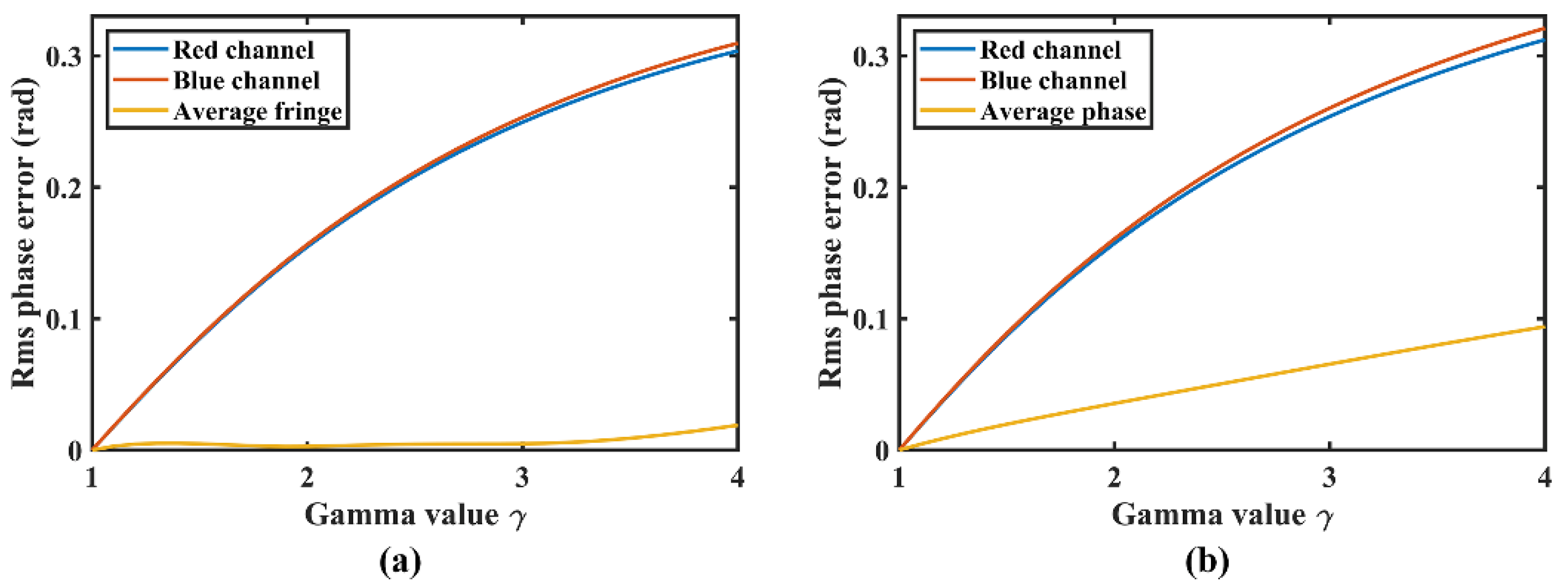
3.3. Different Gamma Values

Moreover, we also explored the accuracy of the IDTP algorithm and the PDTP algorithm under different gamma values, γ = [ 1 , 4 ] . The color crosstalk was set as κ r r = 0.8 , κ b b = 0.9 , κ r b = κ b r = 0.1 . Figure 5a illustrates the Rms phase errors of the IDTP algorithm. In contrast, Figure 5b illustrates the Rms phase errors of the PDTP algorithm. It is evident that the phase errors are almost proportional to the gamma value for both the IDTP algorithm and the PDTP algorithm. For the IDTP algorithm, the Rms phase error of the average fringe is very small, below 0.02 rad, even γ = 4.0. In contrast, for the PDTP algorithm, the Rms phase error of the average phase is larger, and close to 0.1 rad when γ = 4.0. These results confirm that the proposed IDTP algorithm can achieve higher accuracy than the conventional PDTP algorithm under different gamma values.

4. Experiments

To further compare the proposed IDTP algorithm and the conventional PDTP algorithm, some experiments were also carried out. A standard FPP system, including a DLP projector and a CMOS camera, was built up. The projector was Light-Crafter 4500 with a resolution of 912 × 1140 pixels. The camera was Basler a2A1920-160ucBAS with a resolution of 1920 × 1200 pixels. The lens mounted on the front of the camera was Computar M1214-MP2 with focal length of 12 mm. The period of the fringe patterns was set to 21 pixels. A three-step phase-shifting algorithm was used for the wrapped phase calculation, and three-frequency phase unwrapping algorithm was used for absolute phase recovery.
Firstly, a white sphere with smooth surface was measured. Color fringe patterns were generated by the IDTP algorithm and the PDTP algorithm, and then they were projected by the projector and captured by the camera. Figure 6a shows the distorted color fringe for the IDTP algorithm. Note that the adaptive weight was calculated by pixel to suppress the effect of color crosstalk. Figure 6b–d shows the absolute phases recovered from the red channel, the blue channel, and the average fringe, respectively. Clearly, the absolute phases shown in Figure 6b,c contain severe ripple errors, which are mainly caused by gamma nonlinearity. In contrast, the absolute phase shown in Figure 6d contains invisible ripple errors. In contrast, Figure 6e shows the distorted color fringe for the PDTP algorithm. Figure 6f–h shows the absolute phases recovered from the red channel, the blue channel, and the average phase, respectively. Similarly, there are serious ripple errors in Figure 6f,g, and little ripple errors in Figure 6h. For the sake of clarity, Figure 7 illustrates the cross section of the recovered absolute phases of the sphere. The absolute phase recovered from the IDTP algorithm is smoother than that of the PDTP algorithm. It is evident that the proposed IDTP algorithm can effectively correct the gamma nonlinearity.
Secondly, a white sculpture was also measured. For the IDTP algorithm, Figure 8a–d shows the corresponding distorted color fringe, and the absolute phases recovered from the red channel, the blue channel, and the average fringe, respectively. For the PDTP algorithm, Figure 8e–h shows the corresponding distorted color fringe, and the absolute phases recovered from the red channel, the blue channel, and the average fringe, respectively. Figure 9 illustrates the cross section of the recovered absolute phases of the sculpture. The experiment results confirm the performance of the proposed IDTP algorithm compared with the conventional PDTP algorithm.

5. Conclusions

An effective IDTP algorithm was proposed for gamma correction without requiring complex calibration processes or extra fringe patterns. Two phase maps with π/2 phase shift were encoded into the red and blue channels of color fringe patterns. The average fringe patterns with little harmonics were used to restore the accurate phase. The effect of color crosstalk can be suppressed by using an adaptive weight for average operation. The simulations and experiments indicate that the IDTP algorithm can effectively correct the gamma nonlinearity. Additionally, the PDTP algorithm conducts phase-shifting algorithm twice to recover two phase maps, and then computes the average phase map. In contrast, the IDTP algorithm needs to compute the average intensity of two fringe patterns, and then conducts the phase-shifting algorithm once to recover a one phase map, thus the computational efficiency of the IDTP algorithm is higher than that of the PDTP algorithm. Finally, it is still challenging for the proposed method to measure colorful objects, which will be studied in our future research.

Author Contributions

Conceptualization, Y.W. (Yuwei Wang) and Y.W. (Yajun Wang); methodology, Y.W. (Yuwei Wang); software, Y.W. (Yuwei Wang); validation, H.Z. and J.C.; formal analysis, H.Z.; investigation, H.Z.; resources, J.C.; data curation, J.C.; writing—original draft preparation, Y.W. (Yuwei Wang); writing—review and editing, H.Z. and Y.W. (Yajun Wang); visualization, Y.W. (Yuwei Wang); supervision, Y.W. (Yajun Wang); project administration, Y.W. (Yajun Wang); funding acquisition, Y.W. (Yuwei Wang). All authors have read and agreed to the published version of the manuscript.

Funding

This work was supported by the National Natural Science Foundation of China (51905005) and the Natural Science Foundation of Anhui Province (2008085QF318).

Institutional Review Board Statement

Not applicable.

Informed Consent Statement

Not applicable.

Data Availability Statement

Not applicable.

Conflicts of Interest

The authors declare no conflict of interest.

References

  1. Lu, L.; Suresh, V.; Zheng, Y.; Wang, Y.; Xi, J.; Li, B. Motion induced error reduction methods for phase shifting profilometry: A review. Opt. Laser Eng. 2021, 141, 106573. [Google Scholar] [CrossRef]
  2. Geng, J. Structured-light 3D surface imaging: A tutorial. Adv. Opt. Photonics 2011, 3, 128–160. [Google Scholar] [CrossRef]
  3. Chen, R.; Xu, J.; Zhang, S. Comparative study on 3D optical sensors for short range applications. Opt. Laser Eng. 2022, 149, 106763. [Google Scholar] [CrossRef]
  4. Wang, Y.; Wang, C.; Cai, J.; Xi, D.; Chen, X.; Wang, Y. Improved spatial-shifting two-wavelength algorithm for 3D shape measurement with a look-up table. Appl. Opt. 2021, 60, 4878–4884. [Google Scholar] [CrossRef] [PubMed]
  5. Xu, J.; Zhang, S. Status, challenges, and future perspectives of fringe projection profilometry. Opt. Laser Eng. 2020, 135, 106193. [Google Scholar] [CrossRef]
  6. Hu, Y.; Chen, Q.; Feng, S.J.; Zuo, C. Microscopic fringe projection profilometry: A review. Opt. Laser Eng. 2020, 135, 106192. [Google Scholar] [CrossRef]
  7. Zuo, C.; Feng, S.; Huang, L.; Tao, T.; Yin, W.; Chen, Q. Phase shifting algorithms for fringe projection profilometry: A review. Opt. Laser Eng. 2018, 109, 23–59. [Google Scholar] [CrossRef]
  8. Wang, Y.; Liu, L.; Wu, J.; Chen, X.; Wang, Y. Enhanced phase-coding method for three-dimensional shape measurement with half-period codeword. Appl. Opt. 2019, 58, 7359–7366. [Google Scholar] [CrossRef]
  9. Omidi, P.; Najiminaini, M.; Diop, M.; Carson, J.J. Single-shot 4-step phase-shifting multispectral fringe projection profilometry. Opt. Express 2021, 29, 27975–27988. [Google Scholar] [CrossRef]
  10. Cheng, N.-J.; Su, W.-H. Phase-Shifting Projected Fringe Profilometry Using Binary-Encoded Patterns. Photonics 2021, 8, 362. [Google Scholar] [CrossRef]
  11. Wang, Y.; Cai, J.; Zhang, D.; Chen, X.; Wang, Y. Nonlinear Correction for Fringe Projection Profilometry with Shifted-Phase Histogram Equalization. IEEE Trans. Instrum. Meas. 2022, 71, 5005509. [Google Scholar] [CrossRef]
  12. Pan, B.; Kemao, Q.; Huang, L.; Asundi, A. Phase error analysis and compensation for nonsinusoidal waveforms in phase-shifting digital fringe projection profilometry. Opt. Lett. 2009, 34, 416–418. [Google Scholar] [CrossRef] [PubMed]
  13. Zhang, S. Comparative study on passive and active projector nonlinear gamma calibration. Appl. Opt. 2015, 54, 3834–3841. [Google Scholar] [CrossRef]
  14. Babaei, A.; Saadatseresht, M.; Kofman, J. Exponential fringe pattern projection approach to gamma-independent phase computation without calibration for gamma nonlinearity in 3D optical metrology. Opt. Express 2017, 25, 24927–24938. [Google Scholar] [CrossRef]
  15. Xing, S.; Guo, H.W. Directly recognizing and removing the projector nonlinearity errors from a phase map in phase-shifting fringe projection profilometry. Opt. Commun. 2019, 435, 212–220. [Google Scholar] [CrossRef]
  16. Wu, G.X.; Wu, Y.X.; Hu, X.L.; Wu, M.X.; Zhang, S.M.; Liu, F. Exponential Taylor Series Method to eliminate the gamma distortion in phase shifting profilometry. Opt. Commun. 2019, 452, 306–312. [Google Scholar] [CrossRef]
  17. Zhang, S.; Yau, S.T. Generic nonsinusoidal phase error correction for three-dimensional shape measurement using a digital video projector. Appl. Opt. 2007, 46, 36–43. [Google Scholar] [CrossRef]
  18. Hoang, T.; Pan, B.; Nguyen, D.; Wang, Z. Generic gamma correction for accuracy enhancement in fringe-projection profilometry. Opt. Lett. 2010, 35, 1992–1994. [Google Scholar] [CrossRef]
  19. Liu, K.; Wang, S.J.; Lau, D.L.; Barner, K.E.; Kiamilev, F. Nonlinearity calibrating algorithm for structured light illumination. Opt. Eng. 2014, 53, 050501. [Google Scholar] [CrossRef] [Green Version]
  20. Zhang, W.; Yu, L.; Li, W.; Xia, H.; Deng, H.; Zhang, J. Black-box phase error compensation for digital phase-shifting profilometry. IEEE Trans. Instrum. Meas. 2017, 66, 2755–2761. [Google Scholar] [CrossRef]
  21. Yu, X.; Liu, Y.; Liu, N.; Fan, M.; Su, X. Flexible gamma calculation algorithm based on probability distribution function in digital fringe projection system. Opt. Express 2019, 27, 32047–32057. [Google Scholar] [CrossRef]
  22. Liu, Y.K.; Yu, X.; Xue, J.P.; Zhang, Q.C.; Su, X.Y. A flexible phase error compensation method based on probability distribution functions in phase measuring profilometry. Opt. Laser Technol. 2020, 129, 106267. [Google Scholar] [CrossRef]
  23. Huang, P.S.; Hu, Q.J.; Chiang, F.P. Double three-step phase-shifting algorithm. Appl. Opt. 2002, 41, 4503–4509. [Google Scholar] [CrossRef]
  24. Yong, L.; Dingfa, H.; Yong, J. Flexible error-reduction method for shape measurement by temporal phase unwrapping: Phase averaging method. Appl. Opt. 2012, 51, 4945–4953. [Google Scholar] [CrossRef]
  25. Lei, Z.K.; Wang, C.L.; Zhou, C.L. Multi-frequency inverse-phase fringe projection profilometry for nonlinear phase error compensation. Opt. Laser Eng. 2015, 66, 249–257. [Google Scholar] [CrossRef]
  26. Mao, C.L.; Lu, R.S.; Liu, Z.J. A multi-frequency inverse-phase error compensation method for projector nonlinear in 3D shape measurement. Opt. Commun. 2018, 419, 75–82. [Google Scholar] [CrossRef]
  27. Cai, Z.; Liu, X.; Jiang, H.; He, D.; Peng, X.; Huang, S.; Zhang, Z. Flexible phase error compensation based on Hilbert transform in phase shifting profilometry. Opt. Express 2015, 23, 25171–25181. [Google Scholar] [CrossRef]
  28. Chen, H.; Yin, Y.; Cai, Z.; Xu, W.; Liu, X.; Meng, X.; Peng, X. Suppression of the nonlinear phase error in phase shifting profilometry: Considering non-smooth reflectivity and fractional period. Opt. Express 2018, 26, 13489–13505. [Google Scholar] [CrossRef]
  29. Yu, X.; Lai, S.; Liu, Y.; Chen, W.; Xue, J.; Zhang, Q. Generic nonlinear error compensation algorithm for phase measuring profilometry. Chin. Opt. Lett. 2021, 19, 101201. [Google Scholar] [CrossRef]
  30. Wang, Y.; Liu, L.; Wu, J.; Chen, X.; Wang, Y. Hilbert transform-based crosstalk compensation for color fringe projection profilometry. Opt. Lett. 2020, 45, 2199–2202. [Google Scholar] [CrossRef]
  31. Wan, Y.Y.; Cao, Y.P.; Chen, C.; Fu, G.K.; Wang, Y.P.; Li, C.M. Single-shot real-time three dimensional measurement based on hue-height mapping. Opt. Commun. 2018, 416, 10–18. [Google Scholar] [CrossRef]
  32. Wang, Y.P.; Cao, Y.P.; Fu, G.K.; Wang, L.; Wan, Y.Y.; Li, C.M. Single-shot phase measuring profilometry based on color binary grating with intervals. Opt. Commun. 2019, 451, 268–275. [Google Scholar] [CrossRef]
Figure 1. Principle of the proposed IDTP algorithm.
Photonics 09 00173 g001
Figure 2. (a,b) The red and blue channels of the distorted fringe patterns when the gamma value is set to γ = 2.5 ; (c) the average fringe patterns; (d) the undistorted, distorted, and corrected phases, respectively; (e) the nonlinear phase errors.
Photonics 09 00173 g002
Figure 3. Comparison results when ignoring color crosstalk. (a) Color fringe generated by the proposed IDTP algorithm, and the corresponding phase errors of (b) the red channel, (c) the blue channel, and (d) the average fringe, respectively. (e) Color fringe generated by the conventional PDTP algorithm, and the corresponding phase errors of (f) the red channel, (g) the blue channel, and (h) the average phase, respectively.
Photonics 09 00173 g003
Figure 4. Comparison results when considering color crosstalk. (a) Color fringe generated by the proposed IDTP algorithm, and the corresponding phase errors of (b) the red channel, (c) the blue channel, and (d) the average fringe, respectively. (e) Color fringe generated by the conventional PDTP algorithm, and the corresponding phase errors of (f) the red channel, (g) the blue channel, and (h) the average phase, respectively.
Photonics 09 00173 g004
Figure 5. Rms phase errors under different gamma values when using (a) the proposed IDTP algorithm and (b) the conventional PDTP algorithm.
Photonics 09 00173 g005
Figure 6. Comparison results of the sphere. (a) Distorted color fringe for the proposed IDTP algorithm, and the absolute phases recovered from (b) the red channel, (c) the blue channel, and (d) the average fringe, respectively. (e) Distorted color fringe for the conventional PDTP algorithm, and the absolute phases recovered from (f) the red channel, (g) the blue channel, and (h) the average phase, respectively.
Photonics 09 00173 g006
Figure 7. One cross section of the recovered absolute phases of the sphere.
Photonics 09 00173 g007
Figure 8. Comparison results of the sculpture. (a) Distorted color fringe for the proposed IDTP algorithm, and the absolute phases recovered from (b) the red channel, (c) the blue channel, and (d) the average fringe, respectively. (e) Distorted color fringe for the conventional PDTP algorithm, and the absolute phases recovered from (f) the red channel, (g) the blue channel, and (h) the average phase, respectively.
Photonics 09 00173 g008
Figure 9. One cross section of the recovered absolute phases of the sculpture.
Photonics 09 00173 g009
Publisher’s Note: MDPI stays neutral with regard to jurisdictional claims in published maps and institutional affiliations.

