Article

Propagation Characteristics Comparisons between mmWave and Visible Light Bands in the Conference Scenario

1
State Key Laboratory of Networking and Switching Technology, Beijing University of Posts and Telecommunications, Beijing 100876, China
2
China Mobile Research Institute, Beijing 100053, China
*
Author to whom correspondence should be addressed.
Photonics 2022, 9(4), 228; https://doi.org/10.3390/photonics9040228
Submission received: 26 February 2022 / Revised: 18 March 2022 / Accepted: 28 March 2022 / Published: 1 April 2022
(This article belongs to the Special Issue Visible Light Communication (VLC))

Abstract

:
Millimeter-wave (mmWave) communications and visible light communications (VLC) are proposed to form hybrid mmWave/VLC systems. Furthermore, channel modeling is the foundation of system design and optimization. In this paper, we compare the propagation characteristics, including path loss, root mean square (RMS) delay spread (DS), K-factor, and cluster characteristics, between mmWave and VLC bands based on a measurement campaign and ray tracing simulation in a conference room. We find that the optical path loss (OPL) of VLC channels is highly dependent on the physical size of the photodetectors (PDs). Therefore, an OPL model is further proposed as a function of the distance and size of PDs. We also find that VLC channels suffer faster decay than mmWave channels. Moreover, the smaller RMS DS in VLC bands shows a weaker delay dispersion than mmWave channels. The results of K-factor indicate that line-of-sight (LOS) components mainly account for more power for mmWave in LOS scenarios. However, non-LOS (NLOS) components can be stronger for VLC at a large distance. Furthermore, the K-Power-Means algorithm is used to perform clustering. The fitting cluster number is 5 and 6 for mmWave and VLC channels, respectively. The clustering results reveal the temporal sparsity in mmWave bands and show that VLC channels have a large angular spread.

1. Introduction

Motivated by the rising spectrum needs, millimeter-wave (mmWave) communications located in 30–300 GHz (Figure 1) have received great attention in recent years [1,2,3,4], and the channel models have been standardized by groups around the world, such as the 3rd Generation Partnership Project (3GPP) (for 0.5–100 GHz) [5]. Furthermore, the sixth-generation (6G) wireless communication systems are desired for high speed, low latency, and high reliability, which the radio frequency (RF) technologies cannot support. To address such issues, visible light communication (VLC) has emerged to be a key technology in 6G [6,7,8]. VLC employs the unlicensed frequency spectrum resources at 400–800 THz (Figure 1), which can provide a high data transmission rate and a strong resistance to electromagnetic interferences [9,10]. However, the complex applications in 6G have different requirements, which may not be satisfied by a single technology, whether RF or VLC technologies. This requires the combination of multiple communication technologies, e.g., hybrid mmWave/VLC systems [11,12,13]. These two technologies are expected to complement each other to form a reliable communication system in the future.
mmWave and VLC channel modeling is the foundation of designing and optimizing hybrid mmWave/VLC communication systems, which can be used to evaluate the performance and determine the performance limit of wireless communication systems [14]. Moreover, it is also important to understand the differences in the propagation characteristics of VLC and mmWave channels, based on which can exert the respective advantages of mmWave and VLC to design the hybrid mmWave/VLC systems. In the following, we give a review of related works.

1.1. Literature Review

In [13], the authors provided an overview of RF and VLC systems, and they compared the basic system components and modulation techniques of RF and VLC technologies. In [15], the channel frequency response (CFR) of mmWave and VLC channels was investigated. The results show that the channel for VLC is frequency-selective and lowpass, while the channel for mmWave is almost flat. The same results can be found in [16], where the path loss (mmWave) and received power (vehicular VLC) are also given. In [17], the authors presented the results of path loss and time dispersion characteristics for mmWave (measurement) and VLC (simulation), respectively, under different configurations, e.g., room size, transceiver deployment, and operating frequency. They find that mmWave and VLC channels share some common characteristics but also some differences in path loss and time dispersion.
Generally, the existing research of propagation characteristics comparisons between mmWave and VLC bands under the same conditions (conference scenarios and parameters setting) is rare, but it is worth greater attention.

1.2. Contributions of This Paper

The key to propagation characteristics comparisons between mmWave and VLC bands requires the same conditions. In our work, the comparisons are made based on the same conference scenario. The contributions of this paper are as follows:
  • Channel characteristics comparisons between mmWave and VLC bands are performed based on the same conference scenario and parameter settings.
  • A unique optical path loss (OPL) model dependent on the physical size of photodetectors (PDs) is first proposed for VLC based on the widely used floating-intercept (FI) model in mmWave. The size of PDs can be estimated to meet the required coverage range by using this model while designing systems.
  • The large-scale fading characteristics and multipath-related characteristics, including root mean square (RMS) delay spread (DS), K-factor, and cluster characteristics, between mmWave and VLC bands are compared fairly based on the same scenario.
The rest of this paper is organized as follows. Section 2 introduces the scenarios and parameter settings for mmWave and VLC, respectively. Propagation characteristics comparisons are presented in Section 3. Finally, Section 4 concludes this paper.

2. Scenarios and Setup

2.1. Measurement Scenario and Setup in mmWave Bands

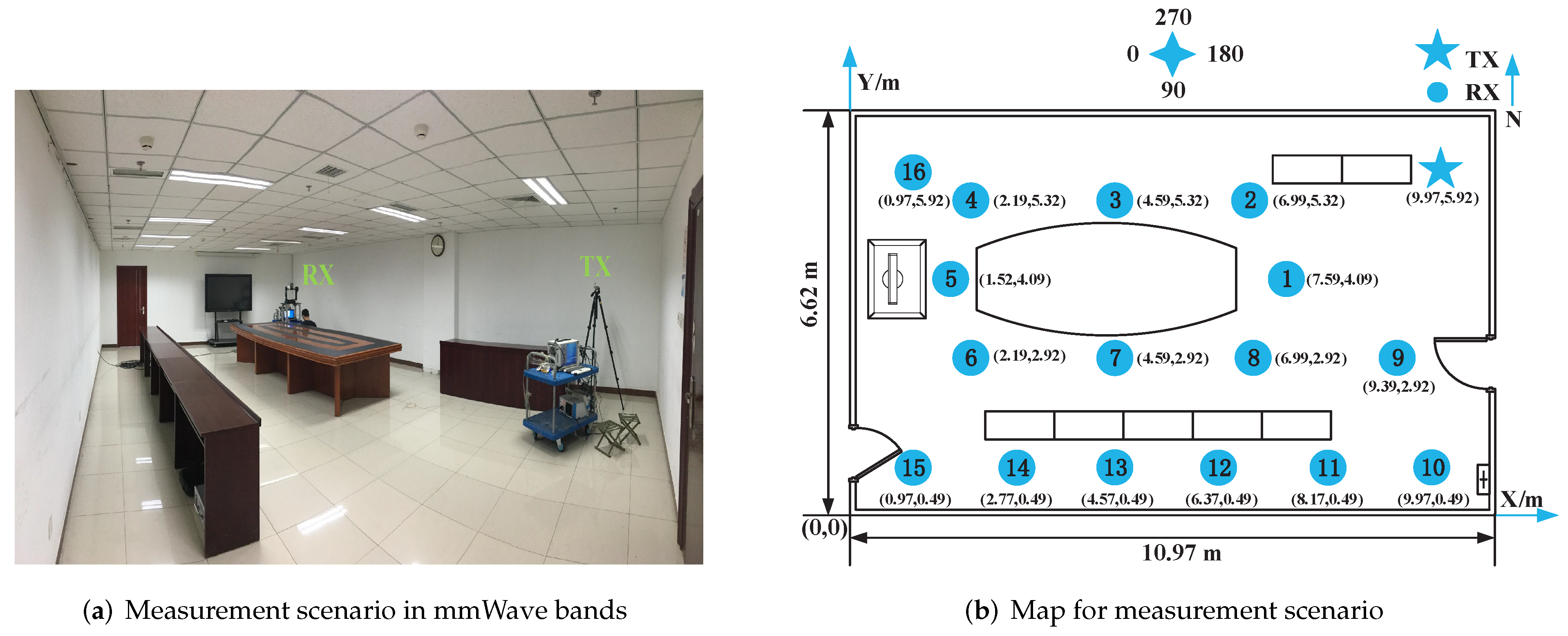
A mmWave channel measurement campaign at 28 GHz was performed with a wideband correlation sounder in a conference room (No. 510) of the Scientific Technology Building at the Beijing University of Posts and Telecommunications (BUPT), as shown in Figure 2a. The map of this room and the 16 measured positions are marked in Figure 2b. The transmitter (TX) is placed at the corner of this conference room while the receiver (RX) is placed at the 16 measured positions successively. The measured distance is within the range of 3 to 10.51 m and all of these measurements are in line-of-sight (LOS) scenarios. In order to obtain the large-scale parameters and small-scale parameters of channels, we used the measurement platform to conduct two kinds of measurements in this conference room.
  • Setup one: Two omnidirectional biconical antennas (360° and 40° half power beam width (HPBW) in azimuth and elevation, respectively) were used at TX and RX sides to collect all multipath components (MPCs), and then 1000 channel impulse responses (CIRs) samples were measured in each position.
  • Setup two: An omnidirectional biconical antenna was used at TX side while a directional horn antenna (10° and 11° HPBW in azimuth and elevation, respectively) was mounted in an electrical positioner at RX side. In these virtual measurements, the TX antenna was fixed and the RX antenna was rotated in steps of 5° in azimuth from 0° to 360°, and there were three different elevations, −10°, 0° and 10°. Channel characteristics in the spatial domain can be obtained through these virtual measurements. In each horn antenna pointing direction, we measured 1000 CIR samples.
Based on these two measurements, we can obtain the path loss, RMS DS, K-factor, and spatial characteristics of mmWave channels. Furthermore, the parameters of the measurement setup are listed in Table 1.

2.2. Simulation Scenario and Setup in VLC Bands

The VLC channel characteristics are investigated based on the ray tracing features of Zemax ® [18] due to the lack of a channel sounding platform for VLC, which is limited by the narrow −3 dB bandwidth (typically around a few MHz) of optical transmitters (LEDs) [19]. VLC channel models developed by this ray tracing method were accepted as reference channel models in IEEE 802.15.13 and IEEE 802.11bb [20]. This channel modeling approach has been demonstrated by experimental results in [21].
In this work, we adopt this well-established realistic channel modeling approach [22]. First, a 3D simulation environment is created, as shown in Figure 3a, where the geometry of the simulation environment can be specified accurately based on the conference room in Figure 2a. Moreover, the CAD models, e.g., tables, desks, and display screen, designed according to the actual measured size in the conference room (No. 510), are imported into the software. The map of this simulation environment and the 16 detector positions are shown in Figure 3b. The wavelength-dependent spectral reflection characteristics of the surface materials (i.e., ceiling, floor, walls, furniture, etc.) are given in Figure 4, which are from [23]. Moreover, we consider the mixed reflections including diffuse and specular reflections by adjusting the scatter fraction (SF) parameter. This parameter changes between 0 and 1 such that zero indicates the purely specular reflections and unity indicates the purely diffuse case. The coating materials of objects in this environment and SF setting are given in Table 2. The specifications of the light sources are shown in Figure 5. These are commercially available light sources (PAR20) with 20° half viewing angle [24], i.e., 40° viewing angle. Considering the 360° and 40° HPBW in azimuth and elevation of mmWave antennas, we use nine LEDs (PAR20) with different pointing from 0° to 360° (interval of 40°) at TX. Therefore, the same coverage as mmWave antennas can be achieved in azimuth (360°) and elevation (40°), as illustrated in Figure 5a. Figure 5b,c illustrate the intensity profiles and the normalized optical spectrum of LED, respectively. Moreover, a spherical PD, as in Figure 3a, called detector polar in Zemax ® , is adopted as the RX antenna. This spherical PD is used in order to collect all the MPCs arriving at the PD, as mmWave antenna does. The photosensitive area of PD can be changed by the radial size (RS), i.e., the radius of detector polar in our simulation. Note that the LEDs and detector are positioned at the same height of 1.68 m as the mmWave antennas at RX.
The non-sequential ray tracing features of Zemax ® can be used to calculate the received power and path lengths from the light source to detector for each ray, which can be further used to obtain the CIRs between the light source and the detector point. In our simulation, the detector is placed at the 16 positions, respectively. Here, Monte Carlo analysis and Sobol sampling are adopted as the random ray tracing methods. The number of reflections was determined based on the simulation of particular ray propagation, where the normalized intensity dropped to 10 3 , i.e., the value of parameter “minimum relative ray intensity” in Zemax ® . All other key parameters can be found in Table 2.

3. Channel Characteristics Comparisons

3.1. Channel Impulse Responses

For a wideband mmWave channel, the receiver can resolve multiple paths according to their delay and the CIRs are commonly represented by the superposition of many plane waves. Furthermore, in our measurements, only two students who operated the measurement platform stayed in the conference room, and they tried to keep stationary during the measurement. Thus, time variance can be ignored here. The CIRs are given as follows:
h ( τ ) = V δ ( τ τ 0 ) + n = 1 N a n e j ϕ n δ ( τ τ n ) ,
where V presents the deterministic (typically LOS) component with the excess delay τ 0 . The parameters a n , τ n , and ϕ n are the amplitude, excess delay, and initial phase of the nth stochastic component, i.e., typically non-LOS (NLOS) component, respectively. N denotes the number of multiple paths.
For VLC channels, the ray tracing process will end with an output file, including the detected optical power and path lengths from sources to the detector for each ray. Then, we can obtain the CIRs based on these data, as in [18]:
h ( τ ) = i = 1 N r P i δ ( τ τ i ) ,
where the P i and τ i are the received optical power and propagation delay of ith ray, and N r denotes the number of received rays at the detector.
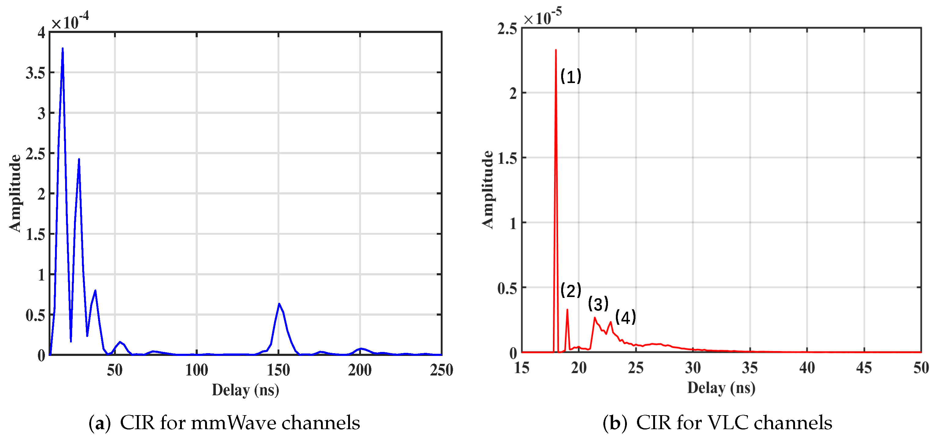
The CIRs at the 10th position are given in Figure 6a,b for mmWave and VLC, respectively. It is observed from Figure 6b that the delay of the first peak (LOS) is 18 ns, with which multiplied by the speed of light ( 3 × 10 8 m/s) we can obtain the LOS distance (5.4 m). It can be verified that the LOS distance is equal to the distance from TX to the 10th position (5.43 m) in Figure 3b, as the blue line shows. The second peak in Figure 6b is close to the LOS, so we can infer that it mainly comes from the reflections of the east door (red lines in Figure 3b). Moreover, the delay of the third and fourth peaks is 21.4 ns and 22.8 ns, i.e., the propagation distances are 6.42 m and 6.84 m, respectively. The green route in Figure 3b means T X the south wall R X and the path distance is 6.41 m ( 0.49 × 2 + 5.43 6.42 m). Therefore, the third peak mainly comes from the reflections from the south wall. Furthermore, the fourth peak is mainly from the north wall, as the black route presents with a path distance of 6.83 m ( 0.7 × 2 + 5.43 6.84 m) in Figure 3b.
We find that mmWave channels have more peaks than those in VLC channels, which can also be found at other points. This result indicates that the mmWave signals can be received at RX through the reflections of more scatters but a few reflections by specific scatters can reach the detector for VLC. Moreover, mmWave channels present a larger delay fluctuation (130 ns) than that of VLC channels (20 ns), which can be explained by the diffuse reflections of VLC, i.e., the light rays split into many random rays and they are reflected in all directions when interacting with scatters. Finally, only small rays can reach the detector.

3.2. Path Loss

Path loss is the reduction in power density of a radio wave as it propagates [25]. In wireless communication systems, the path loss is of high importance for coverage prediction and interference analysis [26,27]. For mmWave channels, the path loss is a function of distance and can be written by [14]:
PL ( d ) = P T + G T + G R + G S + 20 log 10 ( λ 4 π d ) P R ,
where G T , G R , and G S are the antenna gain of TX, RX, and the system gain, respectively; λ is the wavelength; d is the spatial distance between TX and RX; P T is the transmitter power, and P R = 10 log 10 ( n = 1 N ( V 2 + a n 2 ) ) denotes the received power in our measurements.
In each measured position, we can collect 1000 samples of path loss from the first kind of measurements. We can model path loss in this conference room based on these samples with the widely used floating-intercept (FI) [5] and close-in (CI) [28] model. The FI and CI model can be expressed as
PL FI ( d ) = β + 10 α log 10 ( d ) + X σ FI ,
PL CI ( f , d ) = 20 log 10 ( 4 π d 0 f c ) + 10 n C I log 10 ( d d 0 ) + X σ CI   for d d 0 , d 0 = 1 m ,
where β is the intercept, α and n C I are the parameters of fit, i.e., path loss exponent (PLE), X σ is a zero-mean Gaussian variable representing the shadowing, and d 0 is the reference distance.
For VLC channels, the impulse responses of LEDs and PDs have not been standardized as with the antennas in mmWave bands. Therefore, the characteristics of LEDs and PDs are considered in the existing channel models [29,30,31] for VLC. The channel path loss coupled with transceivers is defined as OPL, which can be expressed as [18,32]:
OPL ( d ) = 10 log 10 0 h d ( τ ) d τ ,
where the h d ( τ ) denotes the CIR for the distance d. The CI model cannot be applied to model the OPL in VLC bands, because this model requires a specific frequency (i.e., f in (5)), while the LEDs work with mixed wavelengths, as shown in Figure 5c. Therefore, we choose the FI Model (4) to fit the OPL for VLC channels.
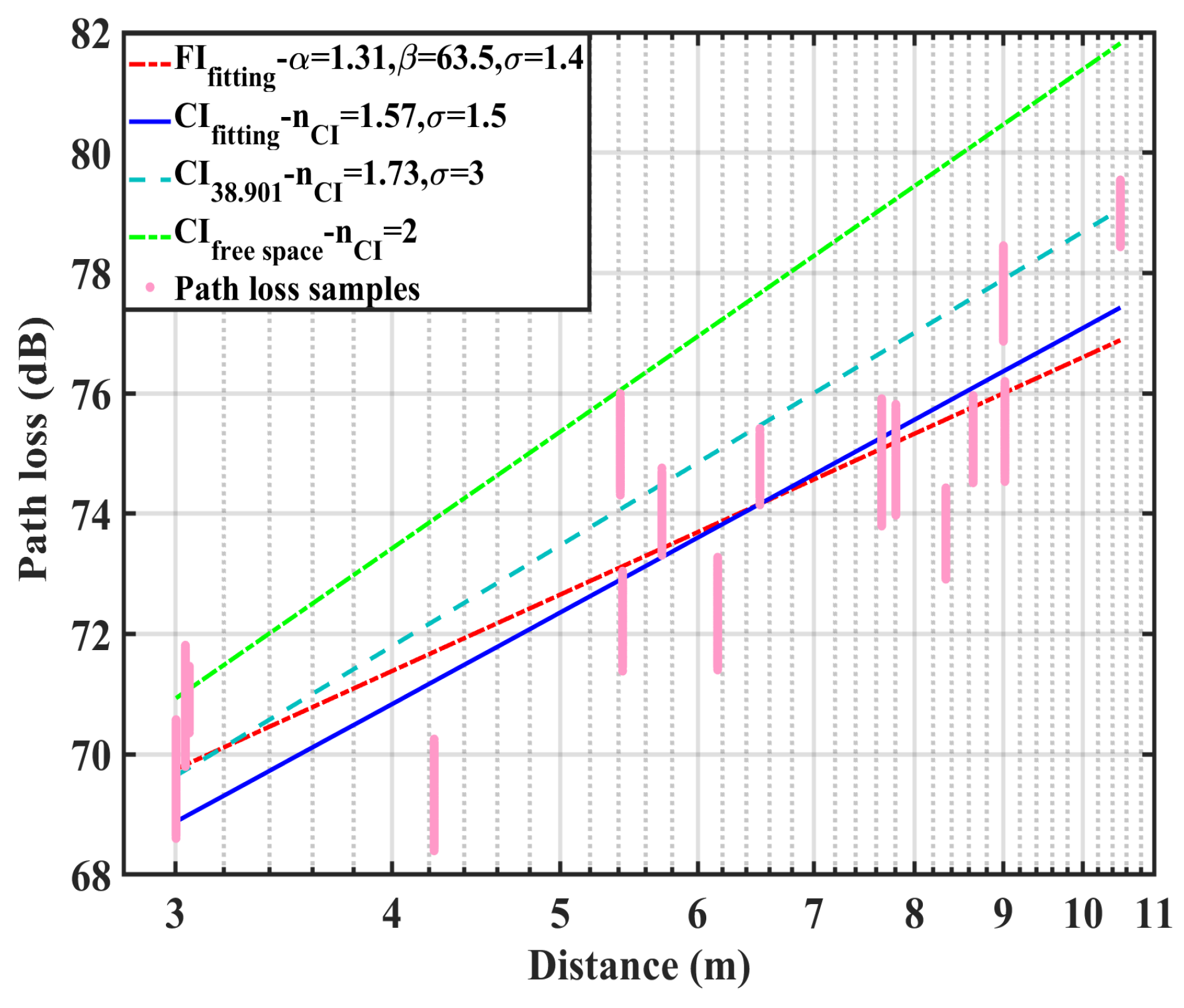
Figure 7 shows the path loss fitting results in mmWave bands. The PLE in the FI model is 1.31, which is slightly smaller than the PLE (1.57) in the CI model. This difference can also be found by investigating the intercept of these two slopes. The intercept β in the FI model is 63.5 dB, while it is 61.34 dB in the CI model. On the other hand, the standard derivation σ in the CI model is 0.1 dB larger than that in the FI model. Generally, these two models can give good insights into the path loss here, and the FI model appears to fit better with the path loss samples, i.e., smaller standard derivation. We also plot the path loss model defined in the 3GPP technical report (TR) 38.901 for the indoor office LOS scenario [5]. We can find that the PLE and σ parameters in this model are both larger than the fitted parameters here. This can be explained by the fact that the typical office room in 3GPP TR 38.901 has more complicated structures than the conference room in Figure 2a, so that the signals are more likely to be obstructed by objects, e.g., the tables, chairs, and plants. Moreover, the path loss model in free space is also presented in Figure 7, and it is apparent that the path loss in free space is larger than the path loss in our measured conference room and the office room. This is within expectation because more reflected signals from walls and ceilings in indoor rooms can be received by the RX.
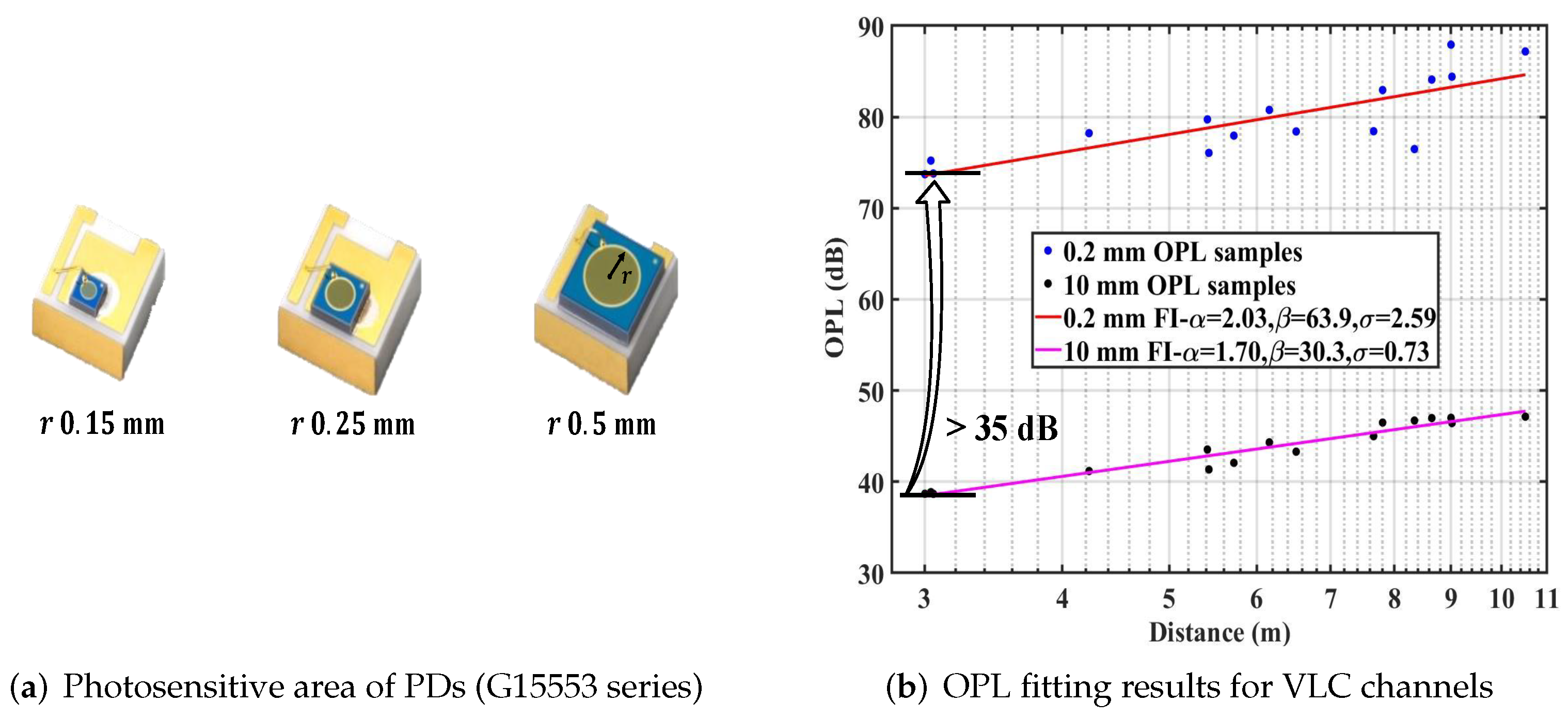
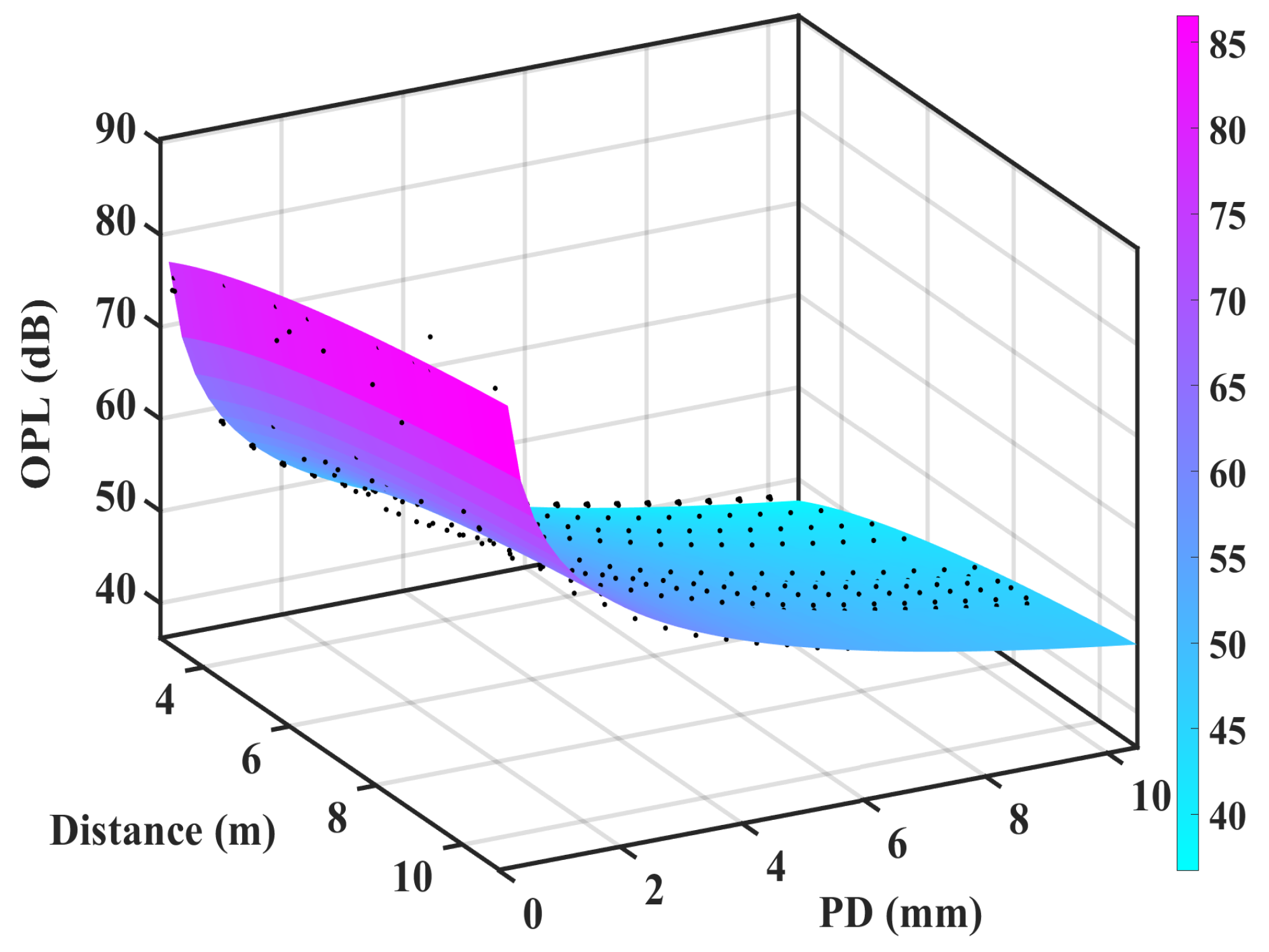
Figure 8a shows the photosensitive area of commercial PDs [33] and r denotes the RS of PDs. It is clear that the OPL is related to the size of PDs. Figure 8b presents the OPL fitting results in VLC bands with RS set to be 0.2 and 10 mm, respectively. It is noteworthy that the OPL of VLC is highly dependent on the size of PDs, which is set by RS in our simulation. The OPL varies between 38.7 and 47.7 dB when RS is 10 mm. However, it varies from 73.6 to 87.2 dB with RS set to be 0.2 mm. Note that the OPL increases by more than 35 dB at the same position when we change the size of PDs in VLC bands. Consistent with our expected results, the OPL will increase with smaller detectors because of the decrease in received rays.
Furthermore, the RS is set in steps of 0.5 mm from 10 to 0.5 mm in our simulations, so that we can obtain the OPL samples with different sizes of PDs in Figure 9. We can model the OPL based on these samples with the FI model. In addition, we propose an OPL model for VLC channels as a function of the spatial distance and size of PDs based on the FI Model (4) through curve fitting techniques. This proposed OPL model can be used to estimate the physical size of PDs to meet the required coverage range while designing systems, which can be expressed as:
OPL ( d , r ) = β + 10 α log 10 ( d ) + γ log 10 ( 1 r 3 ) + X σ ,
where r denotes the RS of PDs. The parameter α , i.e., PLE, is 1.73, which is larger than the PLE in mmWave (1.31). This result reveals that VLC channels suffer faster decay than mmWave channels with increasing distance in the conference room. The parameter β (50.84) is smaller than that in mmWave bands (63.5). This is mainly because the path loss is always lower than that in mmWave bands when RS is set to be greater than 1 mm, i.e., most of the RS sets (0.2, 0.5–10 mm) in our simulation present the lower OPL in VLC bands. The parameter γ (6.98) is defined as a coefficient related to the size of PDs. Moreover, the standard derivation σ representing shadowing fading is 0.99.

3.3. RMS DS

RMS DS describes the time dispersion of MPCs, and it can be used to calculate the coherence bandwidth [34]. Furthermore, large DS may cause inter-symbol interference. The RMS DS can be calculated as follows [35]:
τ RMS = n = 1 N ( τ n τ mean ) 2 P ( τ n ) n = 1 N P ( τ n ) ,
τ mean = n = 1 N τ n P ( τ n ) n = 1 N P ( τ n ) ,
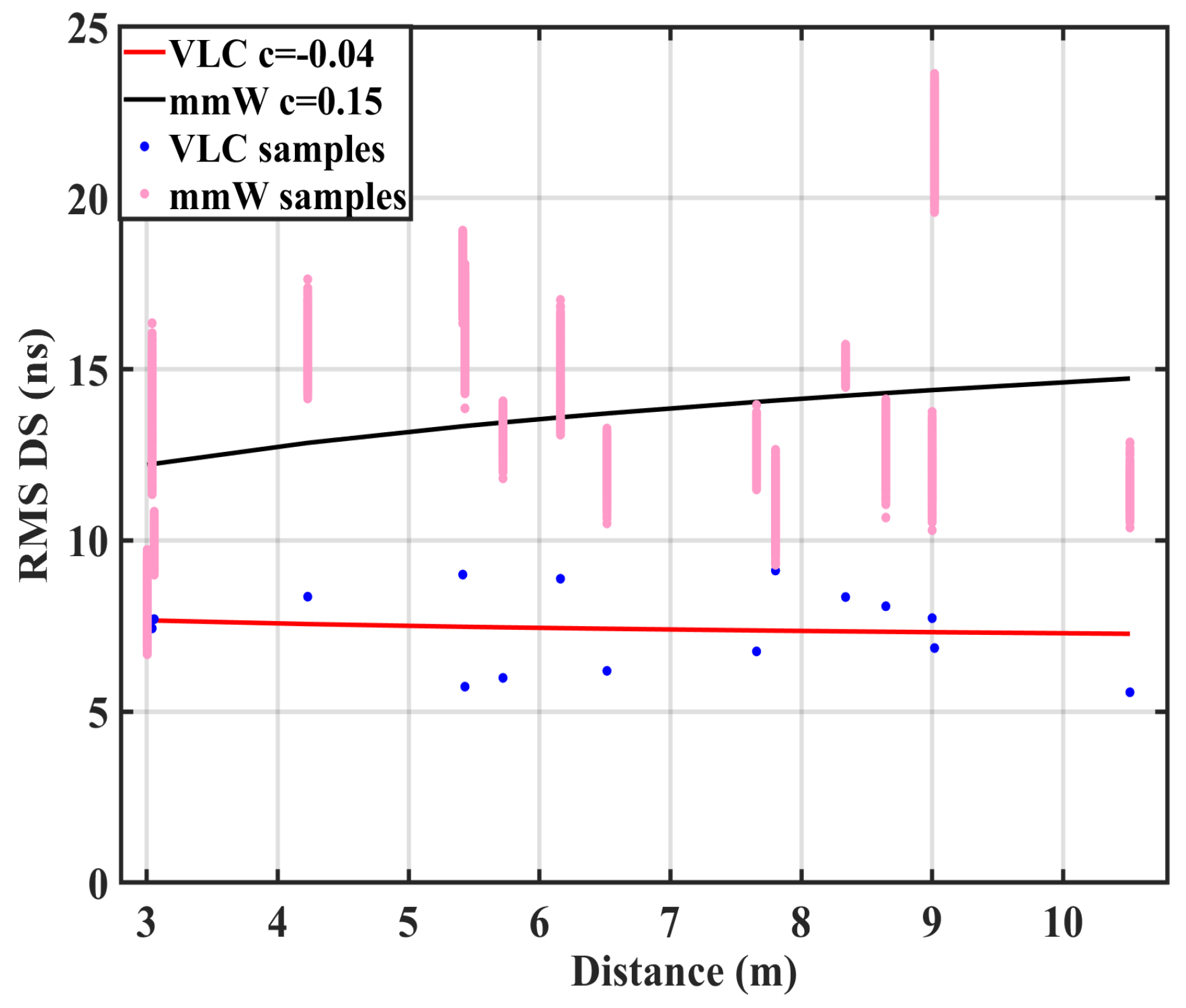
where n is the index of paths, τ n and P ( τ n ) are the delay and power of the nth path, and τ mean is the mean excess delay given by (9). Figure 10 presents the RMS DS for mmWave and VLC channels calculated by (8) and (9). To model the RMS DS, the distance-dependent model is selected as a candidate model in 3GPP [5,36]. We can model the RMS DS with the distance-dependent model as shown in [37],
τ rms d c ,
where d is the distance between TX and RX, and c is a constant, which in this case is 0.15 and −0.04 for mmWave and VLC channels, respectively. Moreover, the confidence interval for c with the 95% confidence level is [0.141–0.159] and [−0.256–0.172] for mmWave and VLC channels, respectively. Note that the values of c in the confidence interval for mmWave are always positive, which indicates that the RMS DS will increase with distance for mmWave channels in this conference room. Moreover, this paper shows smaller RMS DS than that in [37] (28–38 ns). This is mainly because the environment in [37] is larger and more complicated, resulting in greater RMS DS. On the contrary, both positive and negative values appear in the confidence interval for VLC channels. This result indicates that RMS DS is little dependent on the distance for VLC channels in this conference room. This can be explained by the fact that the light rays experiencing complicated reflections are attenuated greatly and reflected in all directions, so that they can barely reach the RX, resulting in the small RMS DS in VLC bands.
In Figure 11, we plot the cumulative distribution function (CDF) of RMS DS for mmWave and VLC channels, respectively. The μ and σ parameters in normal fitting are −7.88 ( 10 7.88 13.18 ns ) and 0.1 for mmWave channels, while they are −8.13 (10 8.13 ≈ 7.41 ns ) and 0.07, respectively, for VLC channels. This indicates that the delay dispersion is weaker in VLC bands than that in mmWave bands, i.e., propagation distances of multipath rays are mostly close due to the few received multipath rays experiencing complicated reflections with a large excess delay in VLC bands.

3.4. K-Factor

K-factor is a measure of the severity for the small-scale fading. Knowledge of K-factor statistics is essential for the design and performance analysis of wireless systems. Furthermore, K-factor is defined as the ratio of the power of the deterministic MPC (typically LOS) and the power of all other stochastic MPCs (typically NLOS). Thus, we can obtain the K-factor according to (1), as shown in (11). However, it is difficult to distinguish which one is a LOS component and which one is an NLOS component from the measured CIRs for mmWave channels. Sometimes, one delay bin may contain both the LOS and NLOS components. Here, we applied the moment method to estimate the K-factor based upon the analysis of frequency selectivity for mmWave channels [38,39].
K = | V | 2 n = 1 N | a n | 2 .
For VLC channels, we obtain the channel characteristics by the ray tracing method. Therefore, we can distinguish the LOS and NLOS components clearly based on the source output file. The K-factor for VLC channels can be expressed according to its definition as:
K = n L O S = 1 N L O S P ( n L O S ) n N L O S = 1 N N L O S P ( n N L O S ) ,
where the N L O S and N N L O S are the numbers of LOS and NLOS rays, respectively.
The CDF of the estimated K-factor and its normal fitting for mmWave channels is shown in Figure 12a. It shows that 20 % of the K-factor values are less than 0 dB and these values are from the 10th ( 5.43 m ) and 16 th ( 9.0 m ) measured points. It appears that NLOS components account for more power in these two points, especially in the 16th point. This is mainly because these two points are close to the walls, which means more reflection components, resulting in the small K-factor. However, 74 % of the K-factor values for VLC channels are less than 0 dB in Figure 12b, and this happens when the distance between TX and RX is larger than 5.43 m (10th point). This indicates that NLOS components are stronger at a large distance in this conference room. Note that the K-factor in VLC bands is 9 dB lower than that in mmWave bands when the distance is 3 m. This can be explained by the definition of K-factor in (12). It is clear that whether there are one or nine LEDs placed at the TX side, the number of LOS components ( N L O S ) is fixed. In our simulation, we place nine LEDs successively at TX to obtain the same coverage as mmWave antennas in azimuth (360°), which is required for a fair comparison. This brings more MPCs received by the detector, i.e., more NLOS rays ( N N L O S ), resulting in the small K-factor. In addition, the μ parameter in the normal fitting is 2.88 dB for mmWave channels, while it is −1.03 dB for VLC channels. These results suggest that it is better to select mmWave technologies when large coverage is required, i.e., VLC technologies are expected for short-range communication.
In Figure 12c,d, we plot both the RMS DS and K-factor with the distance. The distance dependence of these two parameters seems not apparent. Furthermore, we can see that these two parameters appear to present a similar trend, varying with the distance, i.e., the K-factor is proportional to the RMS DS in the conference room. Moreover, the correlation coefficients calculated by (13) are −0.22 and 0.77 for mmWave and VLC channels, respectively. The coefficient −0.22 shows a negative correlation between RMS DS and K-factor, which is demonstrated by the fact that the valley value corresponds to the peak value when the distance is 8 m in Figure 12c. It can also be verified that RMS DS and K-factor in the VLC bands have a higher correlation ( 0.77 > 0.22 ), as seen in Figure 12d.
ρ X , Y = c o v ( X , Y ) v a r ( X ) v a r ( Y ) ,
where c o v ( · ) and v a r ( · ) represent the covariance and variance, respectively.

3.5. Cluster Characteristics

The clustered delay line (CDL) model has been used widely in wireless mobile channel standardization, e.g., 3GPP TR 38.901 [5]. In this model, a cluster means a group of similar MPCs, and MPCs can be clustered from delay and angle dimensions.
Here, we use the K-Power-Means algorithm [40] with a novel initial step [41] to perform clustering. For mmWave channels, multipath information, including amplitude, delay, azimuth angle of arrival (AOA), and elevation angle of arrival (EOA), is estimated by the space-alternating generalized expectation-maximization (SAGE) algorithm [42]. For VLC channels, the ray tracing method is adopted and the parameters such as AOA and EOA can be obtained by geometric calculation.
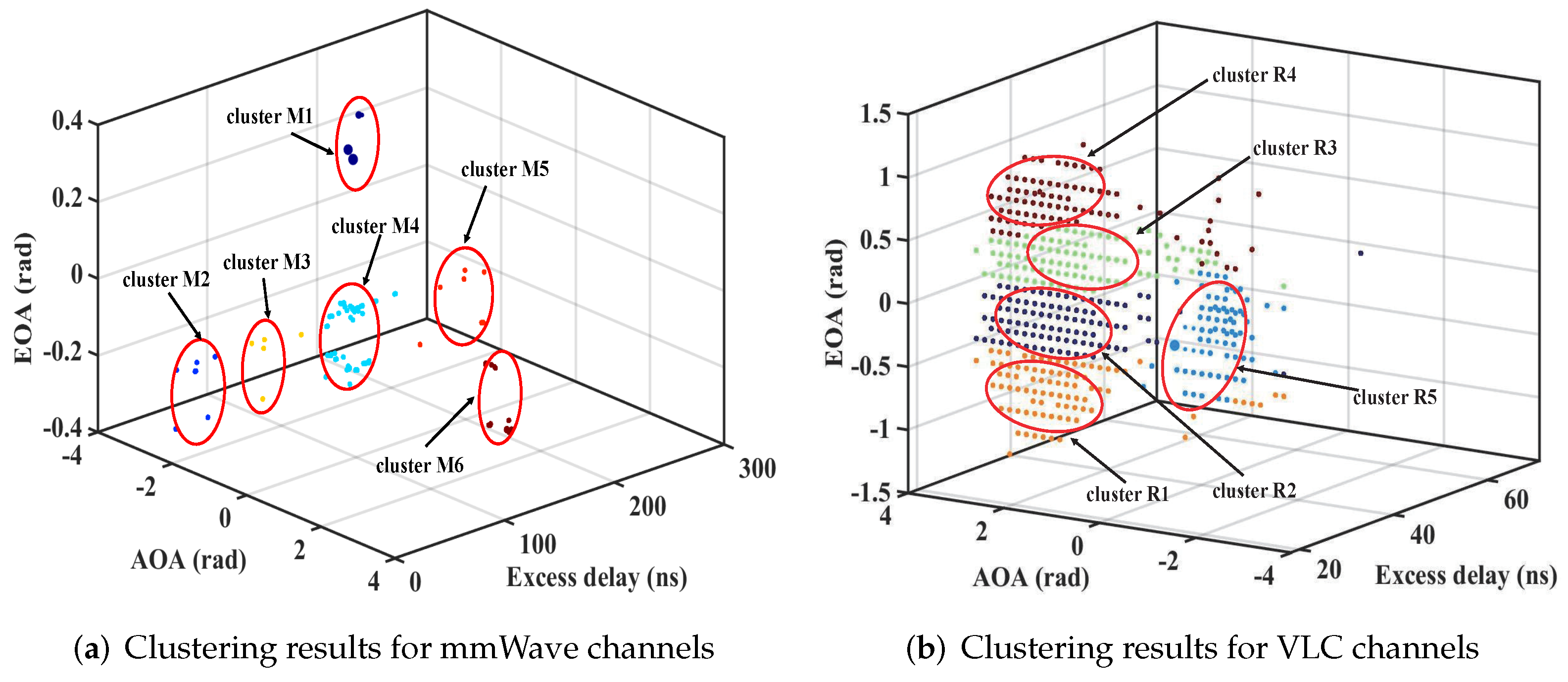
In Figure 13a,b, the clustering results at the 10th position are presented. Clusters for mmWave and VLC channels are marked with M and R, respectively. Moreover, the points with the same color belong to one cluster. It is clear that there are six clusters divided for mmWave while there are five clusters for VLC at the same position. Obviously, these two clustering results are different despite the similar cluster numbers that they have. It is apparent that the MPCs for mmWave can be distinguished more easily in the delay dimension for this measured scenario because the clusters seem to be located in different delay bins, with small fluctuations in AOA and EOA within one cluster. This shows the temporal sparsity in mmWave bands in this conference scenario. However, the difference can be found by investigating the clusters in Figure 13b, which shows that the delay of different clusters is close while the angle dimension (AOA and EOA) varies dramatically, i.e., large angular spread in VLC bands, and we can obtain the same results at other points in this room. This can be explained by the radio wave propagation mechanisms. The light rays have a much smaller wavelength than mmWave signals. The reflection case occurs with similar directions when mmWave signals arrive the surfaces of materials, while the light rays are scattered randomly in all directions, resulting in a large angular spread, in VLC bands.
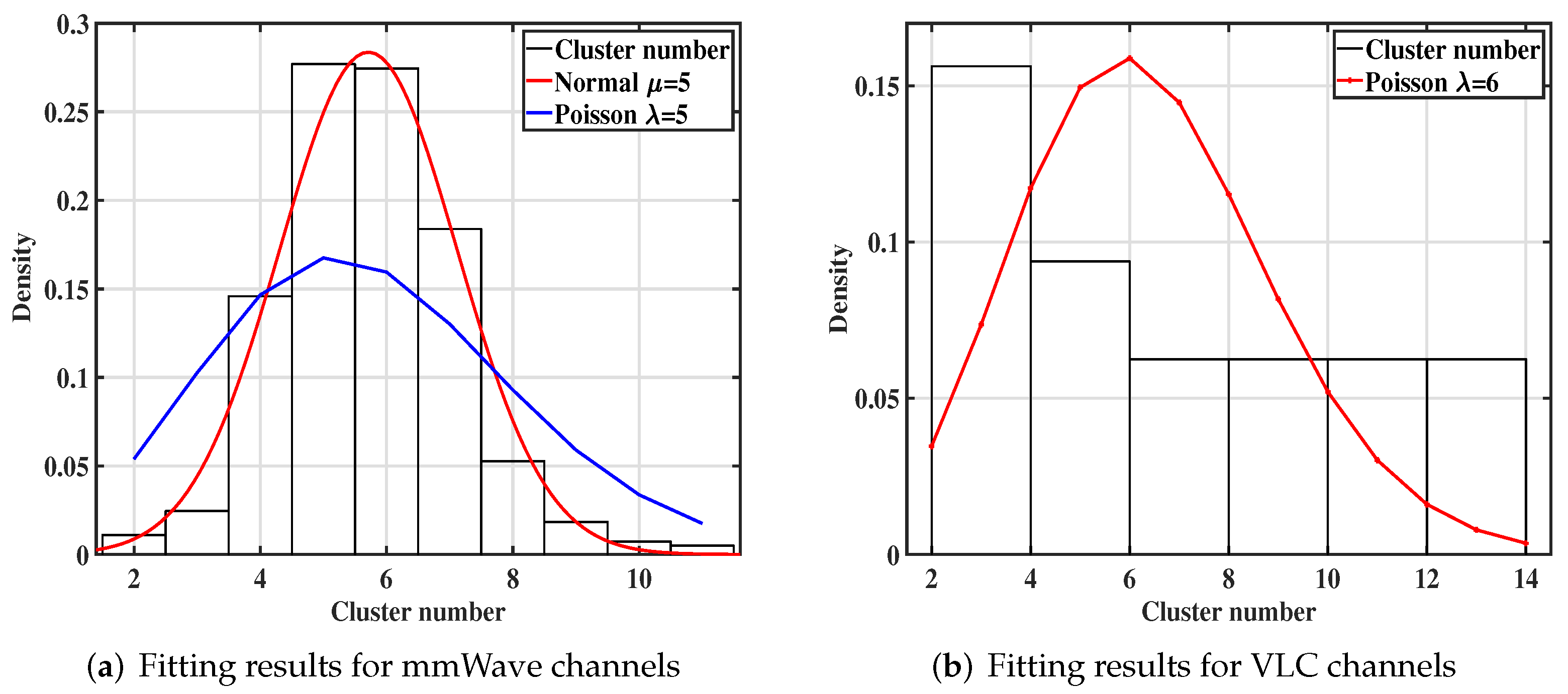
In the standardization channel model, the number of clusters is commonly fixed and made equal to what exists in bands below 6 GHz. For example, the number of clusters is 15 for indoor LOS scenarios in [5]. However, sparsity in the mmWave bands makes this assumption unreasonable [43,44]. The typical cluster numbers reported in [45,46] are small and random with a Poisson distribution. In our work, Figure 14a,b present the statistics of cluster numbers. The Poisson distribution is used to fit the cluster numbers. The fitting parameter λ denotes the average value of cluster numbers, and they are 5.71 and 6.38 for mmWave and VLC, respectively. Here, we consider that the λ is 5 in mmWave bands, and it is 6 in VLC bands because the cluster numbers are expected to be integers.
To confirm our results in the conference scenario, the statistical test method in Statistics, e.g., Kolmogorov–Smirnov test (KS-test) [47], is used to decide if the cluster numbers follow the Poisson distribution. The confidence interval and significance level are 95 % and 0.05, respectively. The test result, i.e., the significance probability p-value for mmWave and VLC, is 0 (<0.05) and 0.547 (>0.05), respectively. The results indicate that VLC cluster numbers follow the Poisson distribution, while the mmWave cluster numbers may not follow the Poisson distribution. We can infer that mmWave cluster numbers may follow the normal distribution from its histogram in Figure 14a, and correspondingly we plot the normal curve to fit the cluster numbers. The fitting result shows that the histogram and normal curve of mmWave cluster numbers can fit well together, which indicates that mmWave cluster numbers follow the normal distribution [48]. In general, the results indicate that the cluster numbers are overestimated in the standardization channel model, and this work can be supplemental in the 3GPP standardization works.

4. Conclusions and Future Work

This paper focuses on the propagation characteristics comparisons between mmWave and VLC bands in indoor scenarios based on the measurement campaign and ray tracing simulation. The results are analyzed based on the conference room. We find that the OPL of VLC channels is highly dependent on the physical size of PDs and an OPL model considering the size of PDs is further proposed. The size of PDs can be estimated to meet the required coverage range while designing systems by using this proposed model. In addition, the PLE is 1.73 for VLC channels, which is larger than that for mmWave channels (1.31). This result reveals that the VLC channels suffer faster decay than mmWave channels with increasing distance in this room. Moreover, mmWave signals can travel farther with a larger RMS DS (13.18 ns) than that of VLC channels (7.41 ns), and the smaller RMS DS in VLC bands shows the weaker delay dispersion compared to mmWave channels. Moreover, the RMS DS of mmWave increases with distance, while it is little dependent on the distance for VLC channels. Furthermore, the mean K-factor for mmWave is 2.88 dB with −1.03 dB for VLC, and LOS components mainly account for more power (80% of K-factor > 0 dB) for mmWave in LOS scenarios, while NLOS components can be stronger (74% of K-factor < 0 dB) at a large distance for VLC channels. The results suggest that it is better to select mmWave technologies when large coverage is required, i.e., VLC technologies are expected for short-range communication. On the other hand, RMS DS and K-factor appear to present a similar trend, varying with distance, i.e., RMS DS is proportional to K-factor for both mmWave and VLC channels. However, this requires further verification. Furthermore, the K-Power-Means algorithm is used to perform clustering from the dimensions of delay and angle. The fitting cluster number is 5 and 6 for mmWave and VLC, respectively. The clustering results reveal the temporal sparsity in mmWave bands and show that VLC channels have a large angular spread.
The propagation characteristics for VLC channels are investigated based on ray tracing methods. Although this channel modeling approach has been demonstrated by experimental results, there are differences between simulation and experimental measurements considering the fact that the reflection coefficients of walls and objects inside the conference room could not be measured and representative values were assumed in the simulations. A channel sounding platform for VLC channels is still needed, which will be our further focus.

Author Contributions

Conceptualization, B.L.; methodology, B.L.; software, B.L. and P.T.; validation, B.L., P.T. and Y.Y.; investigation, B.L. and P.T.; resources, B.L. and P.T.; data curation, B.L. and P.T.; writing—original draft preparation, B.L.; writing—review and editing, P.T. and J.Z.; visualization, B.L.; supervision, J.Z., G.L. and L.X. All authors have read and agreed to the published version of the manuscript.

Funding

This work is supported by the National Science Fund for Distinguished Young Scholars (No. 61925102), the National Key R&D Program of China (No. 2020YFB1805002), the National Natural Science Foundation of China (No. 62031019 and No. 62101069), and BUPT-CMCC Joint Innovation Center (CMYJY-202000276).

Institutional Review Board Statement

Not applicable.

Informed Consent Statement

Not applicable.

Data Availability Statement

Not applicable.

Conflicts of Interest

The authors declare no conflict of interest.

References

  1. Sun, S.; Rappaport, T.S.; Shafi, M.; Tang, P.; Zhang, J.; Smith, P.J. Propagation models and performance evaluation for 5G millimeter-wave bands. IEEE Trans. Veh. Technol. 2018, 67, 8422–8439. [Google Scholar] [CrossRef]
  2. Tang, P.; Zhang, J.; Molisch, A.F.; Smith, P.J.; Shafi, M.; Tian, L. Estimation of the K-factor for temporal fading from single-snapshot wideband measurements. IEEE Trans. Veh. Technol. 2018, 68, 49–63. [Google Scholar] [CrossRef]
  3. Zhang, J.; Shafi, M.; Molisch, A.F.; Tufvesson, F.; Wu, S.; Kitao, K. Channel models and measurements for 5G. IEEE Commun. Mag. 2018, 56, 12–13. [Google Scholar] [CrossRef]
  4. Zhang, J.; Kang, K.; Huang, Y.; Shafi, M.; Molisch, A.F. Millimeter and THz wave for 5G and beyond. China Commun. 2019, 16. [Google Scholar]
  5. 3GPP. Study on Channel Model for Frequencies from 0.5 to 100 GHz. 3rd Generation Partnership Project, Technical Report TR 38.901 V16.1.0. 2019. Available online: https://portal.3gpp.org/desktopmodules/Specifications/SpecificationDetails.aspx?specificationId=3173 (accessed on 12 December 2021).
  6. Chi, N.; Zhou, Y.; Wei, Y.; Hu, F. Visible light communication in 6G: Advances, challenges, and prospects. IEEE Veh. Technol. Mag. 2020, 15, 93–102. [Google Scholar] [CrossRef]
  7. Zhang, J.H.; Tang, P.; Yu, L.; Jiang, T.; Tian, L. Channel measurements and models for 6G: Current status and future outlook. Front. Inf. Technol. Electron. Eng. 2020, 21, 39–61. [Google Scholar] [CrossRef]
  8. Chen, C.; Yang, H.; Du, P.; Zhong, W.D.; Alphones, A.; Yang, Y.; Deng, X. User-centric MIMO techniques for indoor visible light communication systems. IEEE Syst. J. 2020, 14, 3202–3213. [Google Scholar] [CrossRef]
  9. Gunawan, W.H.; Liu, Y.; Chow, C.W.; Chang, Y.H.; Yeh, C.H. High speed visible light communication using digital power domain multiplexing of orthogonal frequency division multiplexed (OFDM) signals. Photonics 2021, 8, 500. [Google Scholar] [CrossRef]
  10. Ji, R.; Wang, S.; Liu, Q.; Lu, W. High-speed visible light communications: Enabling technologies and state of the art. Appl. Sci. 2018, 8, 589. [Google Scholar] [CrossRef] [Green Version]
  11. Delgado-Rajo, F.; Melian-Segura, A.; Guerra, V.; Perez-Jimenez, R.; Sanchez-Rodriguez, D. Hybrid RF/VLC network architecture for the internet of things. Sensors 2020, 20, 478. [Google Scholar] [CrossRef] [Green Version]
  12. Qin, D.; Wang, Y.; Zhou, T. Performance analysis of hybrid radio frequency and free space optical communication networks with cooperative spectrum sharing. Photonics 2021, 8, 108. [Google Scholar] [CrossRef]
  13. Abuella, H.; Elamassie, M.; Uysal, M.; Xu, Z.; Serpedin, E.; Qaraqe, K.A.; Ekin, S. Hybrid RF/VLC systems: A comprehensive survey on network topologies, performance analyses, applications, and future directions. IEEE Access 2021, 9, 160402–160436. [Google Scholar] [CrossRef]
  14. Molisch, A.F. Wireless Communications, 2nd ed.; John Wiley & Sons: New York, NY, USA, 2012. [Google Scholar]
  15. Tavakkolnia, I.; Cheadle, D.; Bian, R.; Loh, T.H.; Haas, H. High speed millimeter-wave and visible light communication with off-the-shelf components. In Proceedings of the 2020 IEEE Globecom Workshops (GC Wkshps), Taiwan, China, 7–11 December 2020; pp. 1–6. [Google Scholar]
  16. Uyrus, A.; Turan, B.; Basar, E.; Coleri, S. Visible light and mmWave propagation channel comparison for vehicular communications. In Proceedings of the 2019 IEEE Vehicular Networking Conference (VNC), Los Angeles, CA, USA, 4–6 December 2019; pp. 1–7. [Google Scholar]
  17. Feng, L.; Yang, H.; Hu, R.Q.; Wang, J. MmWave and VLC-based indoor channel models in 5G wireless networks. IEEE Wirel. Commun. 2018, 25, 70–77. [Google Scholar] [CrossRef]
  18. Miramirkhani, F.; Uysal, M. Channel modeling and characterization for visible light communications. IEEE Photonics J. 2015, 7, 1–16. [Google Scholar] [CrossRef]
  19. Rajagopal, S.; Roberts, R.D.; Lim, S.K. IEEE 802.15. 7 visible light communication: Modulation schemes and dimming support. IEEE Commun. Mag. 2012, 50, 72–82. [Google Scholar] [CrossRef]
  20. Uysal, M.; Miramirkhani, F.; Narmanlioglu, O.; Baykas, T.; Panayirci, E. IEEE 802.15. 7r1 reference channel models for visible light communications. IEEE Commun. Mag. 2017, 55, 212–217. [Google Scholar] [CrossRef]
  21. Eldeeb, H.B.; Uysal, M.; Mana, S.M.; Hellwig, P.; Hilt, J.; Jungnickel, V. Channel modelling for light communications: Validation of ray tracing by measurements. In Proceedings of the 2020 12th International Symposium on Communication Systems, Networks and Digital Signal Processing (CSNDSP), Porto, Portugal, 20–22 July 2020; pp. 1–6. [Google Scholar]
  22. Eldeeb, H.B.; Elamassie, M.; Sait, S.M.; Uysal, M. Infrastructure-to-Vehicle Visible Light Communications: Channel Modelling and Performance Analysis. IEEE Trans. Veh. Technol. 2022, 71, 2240–2250. [Google Scholar] [CrossRef]
  23. ASTER Spectral Library-Version 2.0. Available online: http://speclib.jpl.nasa.gov (accessed on 12 December 2021).
  24. CREE LEDs. Available online: https://www.creelighting.com/products/indoor/lamps/ (accessed on 12 December 2021).
  25. Tang, P.; Zhang, J.; Tian, H.; Chang, Z.; Men, J.; Zhang, Y.; Tian, L.; Xia, L.; Wang, Q.; He, J. Channel measurement and path loss modeling from 220 GHz to 330 GHz for 6G wireless communications. China Commun. 2021, 18, 19–32. [Google Scholar] [CrossRef]
  26. Yu, X.; Zhang, J.; Haenggi, M.; Letaief, K.B. Coverage analysis for millimeter wave networks: The impact of directional antenna arrays. IEEE J. Sel. Areas Commun. 2017, 35, 1498–1512. [Google Scholar] [CrossRef]
  27. Ashikhmin, A.; Li, L.; Marzetta, T.L. Interference reduction in multi-cell massive MIMO systems with large-scale fading precoding. IEEE Trans. Inf. Theory 2018, 64, 6340–6361. [Google Scholar] [CrossRef]
  28. Maccartney, G.R.; Rappaport, T.S.; Sun, S.; Deng, S. Indoor office wideband millimeter-wave propagation measurements and channel models at 28 and 73 GHz for ultra-dense 5G wireless networks. IEEE Access 2015, 3, 2388–2424. [Google Scholar] [CrossRef]
  29. Miramirkhani, F. A path loss model for link budget analysis of indoor visible light communications. Electrica 2021, 21, 242–249. [Google Scholar] [CrossRef]
  30. Lee, K.; Park, H.; Barry, J.R. Indoor channel characteristics for visible light communications. IEEE Commun. Lett. 2011, 15, 217–219. [Google Scholar] [CrossRef]
  31. Qiu, Y.; Chen, H.H.; Meng, W.X. Channel modeling for visible light communications—A survey. Wirel. Commun. Mob. Comput. 2016, 16, 2016–2034. [Google Scholar] [CrossRef] [Green Version]
  32. Elamassie, M.; Karbalayghareh, M.; Miramirkhani, F.; Kizilirmak, R.C.; Uysal, M. Effect of fog and rain on the performance of vehicular visible light communications. In Proceedings of the 2018 IEEE 87th Vehicular Technology Conference (VTC-Spring), Porto, Portugal, 3–6 June 2018; pp. 1–6. [Google Scholar]
  33. Hamamatsu Products. Available online: http://www.hamamatsu.com.cn/product/23464.html (accessed on 12 December 2021).
  34. Janssen, G.J.; Stigter, P.A.; Prasad, R. Wideband indoor channel measurements and BER analysis of frequency selective multipath channels at 2.4, 4.75, and 11.5 GHz. IEEE Trans. Commun. 1996, 44, 1272–1288. [Google Scholar] [CrossRef]
  35. Hashemi, H.; Tholl, D. Statistical modeling and simulation of the RMS delay spread of indoor radio propagation channels. IEEE Trans. Veh. Technol. 1994, 43, 110–120. [Google Scholar] [CrossRef]
  36. Jiang, T.; Zhang, J.; Tang, P.; Tian, L.; Zheng, Y.; Dou, J.; Asplund, H.; Raschkowski, L.; D’Errico, R.; Jamsa, T. 3GPP standardized 5G channel model for IIoT scenarios: A survey. IEEE Internet Things J. 2021, 8, 8799–8815. [Google Scholar] [CrossRef]
  37. Karedal, J.; Wyne, S.; Almers, P.; Tufvesson, F.; Molisch, A.F. A measurement-based statistical model for industrial ultra-wideband channels. IEEE Trans. Wirel. Commun. 2007, 6, 3028–3037. [Google Scholar] [CrossRef] [Green Version]
  38. Greenstein, L.J.; Michelson, D.G.; Erceg, V. Moment-method estimation of the Ricean K-factor. IEEE Commun. Lett. 1999, 3, 175–176. [Google Scholar] [CrossRef]
  39. Bernadó, L.; Zemen, T.; Karedal, J.; Paier, A.; Thiel, A.; Klemp, O.; Czink, N.; Tufvesson, F.; Molisch, A.F.; Mecklenbrauker, C.F. Multi-dimensional K-factor analysis for V2V radio channels in open sub-urban street crossings. In Proceedings of the 21st Annual IEEE International Symposium on Personal, Indoor and Mobile Radio Communications, Istanbul, Turkey, 26–30 September 2010; pp. 58–63. [Google Scholar]
  40. Czink, N.; Cera, P.; Salo, J.; Bonek, E.; Nuutinen, J.P.; Ylitalo, J. Improving clustering performance using multipath component distance. Electron. Lett. 2006, 42, 33–35. [Google Scholar] [CrossRef] [Green Version]
  41. Huang, C.; Zhang, J.; Nie, X.; Zhang, Y. Cluster characteristics of wideband MIMO channel in indoor hotspot scenario at 2.35 GHz. In Proceedings of the 2009 IEEE 70th Vehicular Technology Conference Fall (VTC-Fall), Anchorage, AK, USA, 20–23 September 2009; pp. 1–5. [Google Scholar]
  42. Fleury, B.H.; Tschudin, M.; Heddergott, R.; Dahlhaus, D.; Pedersen, K.I. Channel parameter estimation in mobile radio environments using the SAGE algorithm. IEEE J. Sel. Areas. Commun. 1999, 17, 434–450. [Google Scholar] [CrossRef]
  43. Jiang, T.; Zhang, J.; Shafi, M.; Tian, L.; Tang, P. The comparative study of SV model between 3.5 and 28 GHz in indoor and outdoor scenarios. IEEE Trans. Veh. Technol. 2019, 69, 2351–2364. [Google Scholar] [CrossRef]
  44. Jameel, F.; Wyne, S.; Nawaz, S.J.; Chang, Z. Propagation channels for mmWave vehicular communications: State-of-the-art and future research directions. IEEE Wirel. Commun. 2018, 26, 144–150. [Google Scholar] [CrossRef] [Green Version]
  45. Ju, S.; Xing, Y.; Kanhere, O.; Rappaport, T.S. Millimeter wave and sub-terahertz spatial statistical channel model for an indoor office building. IEEE J. Sel. Areas Commun. 2021, 39, 1561–1575. [Google Scholar] [CrossRef]
  46. Samimi, M.K.; Rappaport, T.S. 3-D millimeter-wave statistical channel model for 5G wireless system design. IEEE Trans. Microw. Theory Tech. 2016, 64, 2207–2225. [Google Scholar] [CrossRef]
  47. Frey, J. An exact Kolmogorov–Smirnov test for the Poisson distribution with unknown mean. J. Stat. Comput. Simul. 2012, 82, 1023–1033. [Google Scholar] [CrossRef]
  48. Arrenberg, J. Analysis of Multivariate Data with SPSS: Workbook with Detailed Examples; Books on Demand Gmbh: Norderstedt, Germany, 2020. [Google Scholar]
Figure 1. The comparison of frequency spectrum resources in mmWave and VLC bands. Generally, mmWave is located in 30–300 GHz. Moreover, some frequencies, e.g., 24 and 28 GHz, are also included in mmWave bands due to their similar characteristics to mmWave.
Photonics 09 00228 g001
Figure 2. Measurement scenario and map for this scenario, in which there are 16 measurement positions in total.
Photonics 09 00228 g002
Figure 3. Simulation scenario and map for this scenario, in which there are 16 detector positions in total.
Photonics 09 00228 g003
Figure 4. Spectral reflectance of various materials.
Photonics 09 00228 g004
Figure 5. The specifications of the light sources, including the emission pattern of LEDs, relative intensity distribution, and relative spectral power distribution.
Photonics 09 00228 g005
Figure 6. CIR at the 10th position.
Photonics 09 00228 g006
Figure 7. Path loss fitting results for mmWave channels.
Photonics 09 00228 g007
Figure 8. Different sizes of commercial PDs and OPL fitting results for VLC channels.
Photonics 09 00228 g008
Figure 9. OPL fitting results for VLC channels considering the physical size of PDs.
Photonics 09 00228 g009
Figure 10. RMS DS fitting results for mmWave and VLC channels.
Photonics 09 00228 g010
Figure 11. The CDF results of RMS DS.
Photonics 09 00228 g011
Figure 12. The results of K-factor and RMS DS.
Photonics 09 00228 g012
Figure 13. Clustering results in the 10th position.
Photonics 09 00228 g013
Figure 14. Fitting results of cluster number.
Photonics 09 00228 g014
Table 1. Parameters of measurement setup.
ParameterValue
Central frequency28 GHz
RF bandwidth600 MHz
Chip sequence length511
Chip rate400 MHz
Delay resolution2.5 ns
Pulse repetition interval1277.5 ns
Biconical antenna/Horn antenna gain2.93 dBi/25 dBi
Biconical antenna/Horn antenna polorizationVertical/Vertical
Biconical antenna/Horn antenna azimuth HPBW360°/10°
Biconical antenna/Horn antenna elevation HPBW40°/11°
TX antenna/RX antenna height1.68 m/1.68 m
Table 2. Parameters of simulation setup.
ItemParameterValue
RoomSize 10.97 × 6.62 × 2.40 m 3
Reflections specificationsNumber of reflections4
Material reflectanceWavelength-dependent
Type of reflectionsSpecular and diffuse reflections
Coating materialWallsPlaster
CeilingCeiling
FloorFloor
Table, desks, and doorsPine Wood
TV screenPlate Window Glass
TV shelf and electric boxGalvanized Steel Metal
Scatter fractionTV screen0.2
Desks and doors0.5
Other objects1
TXModel of LEDPAR20
Number of LED9
Optical power of each LED2 W
Analysis rays 10 7
Minimum relative ray intensity 10 3
ChannelLength d L O S 3–10.51 m
Delay resolution0.2 ns
RXType of receiverDetector Polar
Radial size10 mm
Publisher’s Note: MDPI stays neutral with regard to jurisdictional claims in published maps and institutional affiliations.