Communication

Yoctosecond Timing Jitter Sensitivity in Tightly Synchronized Mode-Locked Ti:Sapphire Lasers

1
Department of Electronics, Peking University, Beijing 100871, China
2
School of Automation Engineering, University of Electronic Science and Technology of China, Chengdu 611731, China
*
Author to whom correspondence should be addressed.
Photonics 2022, 9(8), 569; https://doi.org/10.3390/photonics9080569
Submission received: 5 July 2022 / Revised: 10 August 2022 / Accepted: 11 August 2022 / Published: 12 August 2022
(This article belongs to the Special Issue Mode-Locked Lasers)

Abstract

:
Higher sensitivity in timing jitter measurement has great importance in studies related to precise measurements. Timing jitter noise floors contribute one of the main parts in existing measurements. In this article, a phase error signal is obtained by superposition of outputs of two optical heterodyne discrimination apparatus to suppress the noise floor. Excess phase noise of the electrical amplifier is avoided. We demonstrate 2.6 × 10⁻¹⁴ fs2/Hz (~160 ys/√Hz) timing jitter noise floor between two identical 99 MHz repetition-rate mode-locked Ti:sapphire lasers after their repetition rates are tightly synchronized. The performance is extensible to reach an integrated timing jitter resolution of one attosecond.

1. Introduction

Mode-locked lasers (MLLs) with ultra-low timing jitter are necessary for applications such as photonic analog-to-digital conversion [1], precision optical metrology [2], and timing synchronization in large research facilities [3]. In fields related to precise measurements, phase noise of MLLs, or its integrated effect in the time domain–timing jitter, is a topic in which researchers have enduring interests [4,5,6,7,8,9]. Precision phase error discrimination is fundamental to the timing jitter characterization in pulse trains of MLLs.
The conventional RF (radio frequency) method uses high-speed photodetectors (PDs) and microwave mixers. Pulse trains are firstly converted to RF signals and then measured. Excess phase noise in the photodetection process severely interferes with the measurement sensitivity. A recent study [10] shows that the residual timing jitter between optical pulses and rising edges of photocurrent pulses can reach 64 attoseconds (as) over 1 MHz bandwidth. Falling-edge jitter is much worse.
Balanced optical cross-correlation (BOC) is an attractive approach in the time domain that avoids the photodetection and frequency mixing process [11,12,13,14]. In BOC, two pulse trains under test are combined and guided into two type II phase-matched nonlinear crystals with perpendicular polarization for second harmonic generation (SHG). The difference between two second harmonic pulses is detected by balanced detectors and can reflect the timing jitter. Generated optical pulses are highly narrow compared with RF pulses. Direct comparison between optical pulses can achieve much higher sensitivity.
The optical heterodyne technique is another approach that extracts phase error signals in the frequency domain. Beat notes of frequency comb teeth well separated in spectrum contain 104~106 harmonics of difference of repetition rates [15]. An improved configuration [16] makes full use of a broadband spectrum, increasing the sensitivity further.
Based on the direct optical methods above, timing jitters less than 20 as have been realized on platforms including Ti:sapphire MLLs [17], Er:Yb:glass MLLs [16], and Yb-fiber MLLs [18]. In these experiments, light guided into photodetectors is weak. Electrical amplifiers are generally used after photodetectors to increase the amplitude of signals. However, the noise floor of former circuits is amplified at the same time. Besides jitters between optical pulses, jitters integrated from the noise floor contribute a considerable part to results. A novel approach uses cross-spectrum methods in a dual BOC system [19]. Timing jitter noise floor is suppressed after cross-spectra are averaged thousands of times.
Here we show timing jitter noise floor suppression in tightly synchronized Ti:sapphire MLLs with multiple optical heterodyne units. When outputs of two optical heterodyne units combine, the amplitude of the discrimination signal multiplies without amplifiers. Due to the low electrical noise floor, the timing jitter noise floor at high frequency is reduced to 2.6 × 10⁻¹⁴ fs2/Hz. Jitter induced in lower frequency is compensated by a fast PZT with broad feedback bandwidth. In-loop integrated timing jitter of 5.7 as, measured from 10 kHz to 49.5 MHz (Nyquist frequency), is achieved. More units can be used to achieve one attosecond resolution.

2. Experimental Setup

2.1. Laser Design

To generate a discrimination signal with a slope large enough, the laser source should have broadband and high-power output. Two identical homemade Ti:sapphire mode-locked lasers are used in our experiment. The schematic of one of the laser cavities is shown in Figure 1. Each laser is formed by an x-folded cavity composed of six mirrors and a 2 mm Brewster-cut Ti:sapphire crystal with an absorption coefficient of 7.0 cm−1 at 532 nm.
M1–M4 are double-chirped mirror (DCM) pairs. M2 and M4 are manufactured with the same kind of coating (Layertec, Coating 136768), while M3 and M1 have a complementary coating (Layertec, Coating 136769). These mirrors used in pairs provide a smooth broadband dispersion compensation. M2 and M3 have a radius of curvature (ROC) of 75 mm. M5 is dispersion optimized silver mirror, of which the group-delay dispersion (GDD) is zero, and it is mounted on a piezoelectric transducer (PZT). In one laser, noted as MLL1, a slow PZT is used for a long-range search and a loose locking of repetition rate (fr). In another laser MLL2, a thin piezoelectric ceramic disk (PI, piezoceramic components, PL055.31) is used as a fast PZT, ensuring a precise and quick adjustment of fr. This fast PZT is actuated by a high voltage driving source (THORLABS, HAV200) with 10MHz bandwidth. The reflectivity of the output coupler used here is 90%. The cavity of the resonator is 152 cm long, corresponding to 99 MHz fr. The laser is pumped by a diode-pumped solid-state 532 nm laser (Lighthouse Photonics, Sprout D-7W). The oscillator generates femtosecond pulse trains with an average output power of 1.4 W centered at 800 nm. The full width at half maximum (FWHM) of the generated spectrum is 120 nm, as shown in Figure 2, corresponding to a 16 fs Fourier-limited pulse. The pulse duration is broadened to 20 fs before entering the optical heterodyne units.

2.2. Fast PZT

Broadband feedback is a crucial point to compensate for the noise below several hundreds of kilohertz, which is critical to achieving a tight synchronization. For Ti:sapphire lasers, mechanical noise and relative intensity noise (RIN) play central roles in this low-frequency region. Commercial piezoelectric ceramic disks or pans with thickness below 2 mm can nowadays achieve unloaded resonant frequencies well beyond 1 MHz. PI (proportional integral) circuits and drivers with proper parameters are also not big problems. However, strong resonances in the PZT system composed of a mirror, PZT, and mount limit the feedback bandwidth to a much lower frequency, less than 10 kHz in a common PZT system, for example.
Constructive works have been done to push the limits to a higher frequency [20,21,22]. With special design including damping alloy, wedged structure, impedance matching gel, and modified mirror, Nakamura et al. realized a flat frequency response up to 500 kHz in a PZT-actuated mirror system [22].
The actuator used in this work consists of a mirror, a piezoelectric ceramic disk, a lead cylinder, a rubber ring, and a mirror mount, as demonstrated in Figure 3a. An 8 (diameter) × 15 mm lead cylinder is tightly fixed by a screw on a mirror mount as the base. A rubber ring of 2 mm thickness is used to isolate the cylinder from external mechanical resonances. A wedged surface with an angle of less than 2° is polished on the lead to support the PZT and mirror. The wedged surface can further suppress resonances propagating inside the lead. To achieve a higher frequency response, the size of the PZT and mirror should be small. The PZT is a 5 × 5 × 2 mm disk with an unloaded resonant frequency greater than 600 kHz. The mirror used here has a diameter of 5 mm and a thickness of 2 mm. Super glue (ergo 5800) was used to attach the lead, PZT, and the mirror. To reduce the reflection of mechanical waves induced from interfaces, the attachment should be tight, and the glue layer should be thin. The maximum effective feedback bandwidth measured by a Michelson interferometer reaches about 200 kHz, as shown in Figure 3b.

2.3. Timing Jitter Discrimination

The output powers of two Ti:sapphire lasers are sufficient to support multiple units of optical heterodyne discrimination. In this paper, two same units are used. The setup of each discrimination unit is similar to that described in [16]. The difference is the concave reflectors and lens used to shape the light. As shown in Figure 4, the outputs of two MLLs are combined and divided into two parts equally by a 50:50 broadband nonpolarizing beam splitter (NPBS). In each part, a discrimination unit is realized. Some of the output is also used to lock and control the repetition rates.
In a single unit, a polarizing beam splitter (PBS) splits the beam equally into two linearly polarized beams with orthogonal polarizations. Then the beams are scattered by gratings. The long wavelength tail of one beam and short wavelength tail of another beam are respectively shaped by a silver cylindrical mirror and convex lens. Two photodetectors (PD, Hamamatsu S5972) collect a broadband superimposed light of two lasers at each of the two extremes of the optical spectrum. The discrimination signal is generated after frequency mixing the responses of two PDs.
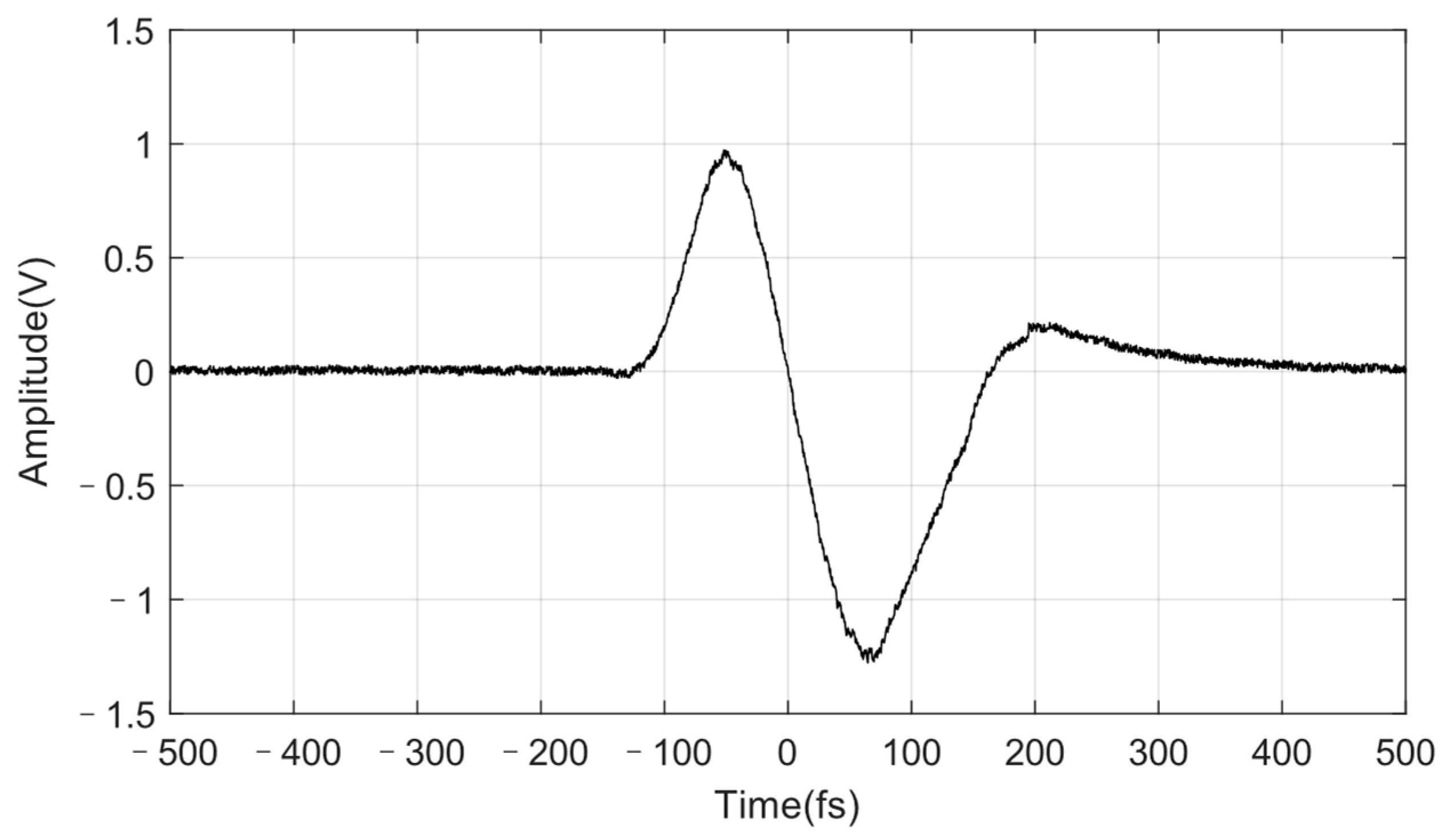
To increase the signal amplitude without amplifiers, the power of the incident laser on each PD exceeds 40 mW, which approaches the limit of PD’s power dissipation. The heating effect introduced by laser is eliminated by embedding the PDs into copper mounts cooled by Peltier elements. Figure 5 shows the response of one unit. The discrimination signal is obvious only with a small difference in repetition rates (Δfr). When Δfr is set to 1 Hz, a signal of 2.2 V is obtained, corresponding to a discriminator slope of 29 mV/fs (±4 mV/fs). Signals of two units are then superposed together by a sum circuit and a final signal of 52 mV/fs (±5 mV/fs) is obtained.

2.4. Passive Methods of Noise Suppression

To suppress acoustic noise and thermal variation, careful attention must be paid both to the design and construction of the system. The pump laser and cavity of each Ti:sapphire laser are fixed on a 300 mm × 600 mm steel baseboard. The cavity is designed to make the light in the cavity close to the baseboard (36.7 mm). Under the breadboard is a cushion composed of a 30 mm sponge, 3 mm rubber, 1 mm lead, 3 mm rubber, 1 mm lead, and 15 mm rubber from top to bottom. A box made of 5 mm aluminum and a 30 mm sponge is used to insulate the laser from acoustic noise outside the box. Cushion and boxes with similar structures are also used in the discrimination stage. The entire system is set on an air-floating optical table.
Variation in temperature influences the alignment of lasers. The discrimination units used now have a rigorous requirement of alignment. Therefore, the temperature must be well stabilized. We use circulating water (20.0 ± 0.1 °C) to cool the pump lasers and Ti:sapphire crystals. The temperature of the environment is 25.5 ± 0.3 °C. Thermal conduction material used in our system is Indium (In) thin film wet with a kind of liquid metal composed of Gallium (Ga), Indium (In), and Stannum (Sn). Its coefficient of thermal conductivity exceeds 80 W/(m·K), which is ten times greater than general thermal grease. Some other means may be helpful to improve the robustness. For example, screws used in the laser cavity are tightened with a torque wrench and thread locker glue to realize a balanced and secure installation.

3. Results and Discussion

When the interference outside the lasers is insulated, repetition rates of two free-running MLLs drift slowly (about 1 Hz/s). To synchronize the repetition rates, we firstly adjust the voltage applied on the slow PZT in MLL1 so that fr of MLL1 approaches fr of MLL2 gradually. A discrimination signal then comes into being in a free-running condition. This signal is subsequently fed back to PI circuits and fast PZT in MLL2. Tight synchronization of fr between two MLLs is finally achieved.
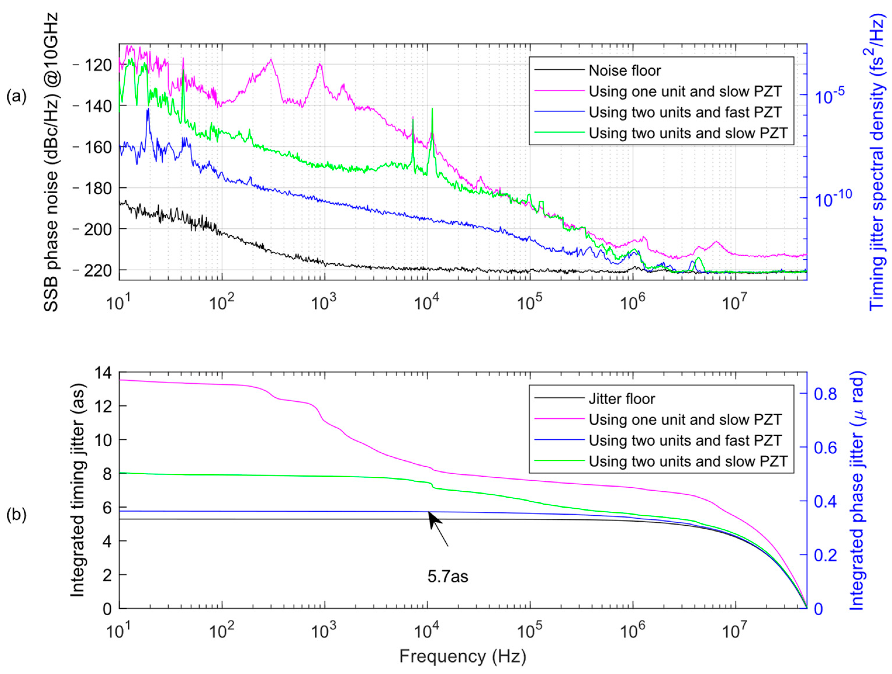
The phase noise spectrum and integrated timing jitter are obtained from amplitude-noise power spectral density measurement with a signal analyzer [23]. The discrimination signal is denoted as U ( Δ t ) , with a slop A = d U / d Δ t at zero crossing point. The slop means a deviation with an amplitude d U corresponds to a timing jitter d U / A . We firstly did baseband measurement to obtain an amplitude-noise power spectral density S U ( f ) of U ( Δ t ) . Then, we did the timing noise spectrum S Δ t ( f ) is S Δ t ( f ) = ( d U / d Δ t ) 2 S U 2 ( f ) . The phase-noise spectral density is L ( f ) = 4 π 2 f r e p , i 2 S Δ t ( f ) . As illustrated in Figure 6, an in-loop RMS timing jitter (blue line, integrated from 10 kHz to 49.5 MHz) reaches 5.7 as (±0.6 as). The noise floor of electric circuits contributes 5.2 as jitter. The calibration errors come from the uncertainty of the slope of the discrimination signal A = d U / d Δ t . This uncertainty is then translated to the result in the above-mentioned calculation. The phase noise and jitter when lasers are synchronized using slow PZT in MLL1 are illustrated in green lines, and the results when lasers are synchronized using only one unit (with an amplifier) and slow PZT are illustrated in bright red as a comparison.
We make four discriminator circuits and measure the noise floors after their outputs are accumulated gradually. The discriminator slopes are set the same (52 mV/fs) in the calculation. As shown in Figure 7a, the use of sum circuits introduces a 2.5 dBc/Hz increase to noise floor in high frequency. Then, increasing the outputs accumulated does not increase the noise floor distinctly. The calculated jitter floor of one unit in Figure 7b seems low because the amplifier is not included, and the jitter is calculated with a slope of two units. In fact, the discriminator slope will multiply with the number of units used, leading to a quick drop in timing jitter noise floor. It is possible to increase the timing jitter resolution by using more units.
Currently, PDs in two units receive 170 mW light in total. The amplitude of the discrimination signal can be easily multiplied by using more units. The efficiency of single units can be further improved [24]. Supposing 60 % of the output is divided or lost before incidence to PDs, 14 units can fully utilize the remaining 1.1 W light. This configuration will give a raising factor of 7 to timing jitter resolution, bringing down the limits of integrated timing jitter resolution set by noise floor to one attosecond.

4. Conclusions

In summary, we demonstrate 2.6 × 10⁻¹⁴ fs2/Hz (~160 ys/√Hz) timing jitter noise floor between Ti:sapphire MLLs. The noise floor in high frequency is reduced with the omission of amplifiers. With outputs of two optical heterodyne discrimination units combined, the amplitude of the phase error signal is enough for feedback. Our next goal is the superposition of more units, which is not an ordinary task. Then, this apparatus will be used in characterizing hardly ever reached noise in MLLs, such as ASE-induced timing jitter and Gordon–Haus timing jitter. These units can also improve the performance of frequency synchronization. The performance shows a potential to improve the discrimination sensitivity to support integrated timing jitter resolution approaching one as. Such precision is necessary for realizing coherent detection with attosecond pulse trains.

Author Contributions

Conceptualization, H.X. and D.H.; methodology, H.X. and D.H.; software, H.W.; validation, H.W. and H.L.; formal analysis, H.L.; resources, Z.L.; data curation, Z.L.; writing—original draft preparation, H.X.; writing—review and editing, H.X.; visualization, H.W. and Z.L.; supervision, D.H. and J.Z.; project administration, J.Z.; funding acquisition, J.Z. and D.H. All authors have read and agreed to the published version of the manuscript.

Funding

This research is supported by the National Natural Science Foundation of China (61535001, 61871084, 91836301).

Institutional Review Board Statement

Not applicable.

Informed Consent Statement

Not applicable.

Data Availability Statement

Not applicable.

Acknowledgments

We thank Zhigang Zhang for suggestion on the Ti:sapphire MLLs and Peng He for constructive discussion.

Conflicts of Interest

The authors declare no conflict of interest.

References

  1. Valley, G.C. Photonic analog-to-digital converters. Opt. Express 2007, 15, 1955–1982. [Google Scholar] [CrossRef] [PubMed]
  2. Udem, T.; Holzwarth, R.; Hänsch, T.W. Optical frequency metrology. Nature 2002, 416, 233–237. [Google Scholar] [CrossRef] [PubMed]
  3. Kim, J.; Cox, J.A.; Chen, J.; Kärtner, F.X. Drift-free femtosecond timing synchronization of remote optical and microwave sources. Nat. Photonics 2008, 2, 733–736. [Google Scholar] [CrossRef]
  4. Coluccelli, N.; Cassinerio, M.; Gambetta, A.; Laporta, P.; Galzerano, G. Frequency-noise measurements of optical frequency combs by multiple fringe-side discriminator. Sci. Rep. 2015, 5, 16338. [Google Scholar] [CrossRef] [PubMed]
  5. Jung, K.; Kim, J. Characterization of timing jitter spectra in free-running mode-locked lasers with 340 dB dynamic range over 10 decades of Fourier frequency. Opt. Lett. 2015, 40, 316–319. [Google Scholar] [CrossRef] [PubMed]
  6. Kim, J.; Song, Y. Ultralow-noise mode-locked fiber lasers and frequency combs: Principles, status, and applications. Adv. Opt. Photonics 2016, 8, 465–540. [Google Scholar] [CrossRef]
  7. Tian, H.; Song, Y.; Meng, F.; Fang, Z.; Hu, M.; Wang, C. Long-term stable coherent beam combination of independent femtosecond Yb-fiber lasers. Opt. Lett. 2016, 41, 5142–5145. [Google Scholar] [CrossRef]
  8. Wang, Y.; Tian, H.; Hou, D.; Meng, F.; Ma, Y.; Xu, H.; Kärtner, F.X.; Song, Y.; Zhang, Z. Timing jitter reduction through relative intensity noise suppression in high-repetition-rate mode-locked fiber lasers. Opt. Express 2019, 27, 11273–11280. [Google Scholar] [CrossRef]
  9. Tian, H.; Song, Y.; Hu, M. Noise measurement and reduction in mode-locked lasers: Fundamentals for low-noise optical frequency combs. Appl. Sci. 2021, 11, 7650. [Google Scholar] [CrossRef]
  10. Hyun, M.; Ahn, C.; Na, Y.; Chung, H.; Kim, J. Attosecond electronic timing with rising edges of photocurrent pulses. Nat. Commun. 2020, 11, 3667. [Google Scholar] [CrossRef]
  11. Schibli, T.; Kim, J.; Kuzucu, O.; Gopinath, J.; Tandon, S.; Petrich, G.; Kolodziejski, L.; Fujimoto, J.; Ippen, E.; Kaertner, F. Attosecond active synchronization of passively mode-locked lasers by balanced cross correlation. Opt. Lett. 2003, 28, 947–949. [Google Scholar] [CrossRef] [PubMed]
  12. Kim, J.; Chen, J.; Zhang, Z.; Wong, F.; Kärtner, F.; Loehl, F.; Schlarb, H. Long-term femtosecond timing link stabilization using a single-crystal balanced cross correlator. Opt. Lett. 2007, 32, 1044–1046. [Google Scholar] [CrossRef] [PubMed]
  13. Ma, X.; Liu, L.; Tang, J. Timing jitter measurement of transmitted laser pulse relative to the reference using type II second harmonic generation in two nonlinear crystals. Opt. Express 2009, 17, 19102–19112. [Google Scholar] [CrossRef]
  14. Song, Y.; Zhou, F.; Tian, H.; Hu, M. Attosecond timing jitter within a temporal soliton molecule. Optica 2020, 7, 1531–1534. [Google Scholar] [CrossRef]
  15. Chen, Y.-F.; Jiang, J.; Jones, D.J. Remote distribution of a mode-locked pulse train with sub 40-as jitter. Opt. Express 2006, 14, 12134–12144. [Google Scholar] [CrossRef]
  16. Hou, D.; Lee, C.-C.; Yang, Z.; Schibli, T. Timing jitter characterization of mode-locked lasers with < 1 zs/√ Hz resolution using a simple optical heterodyne technique. Opt. Lett. 2015, 40, 2985–2988. [Google Scholar]
  17. Benedick, A.J.; Fujimoto, J.G.; Kärtner, F.X. Optical flywheels with attosecond jitter. Nat. Photonics 2012, 6, 97–100. [Google Scholar] [CrossRef]
  18. Kim, H.; Qin, P.; Song, Y.; Yang, H.; Shin, J.; Kim, C.; Jung, K.; Wang, C.; Kim, J. Sub-20-attosecond timing jitter mode-locked fiber lasers. IEEE J. Sel. Top. Quantum Electron. 2014, 20, 260–267. [Google Scholar]
  19. Casanova, A.; Courjaud, A.; Trophème, B.; Santarelli, G. Measurement of absolute timing jitter of SESAM mode-locked lasers with yoctosecond sensitivity. Opt. Lett. 2020, 45, 6098–6101. [Google Scholar] [CrossRef]
  20. Briles, T.C.; Yost, D.C.; Cingöz, A.; Ye, J.; Schibli, T.R. Simple piezoelectric-actuated mirror with 180 kHz servo bandwidth. Opt. Express 2010, 18, 9739–9746. [Google Scholar] [CrossRef]
  21. Goldovsky, D.; Jouravsky, V.; Pe’er, A. Simple and robust phase-locking of optical cavities with> 200 KHz servo-bandwidth using a piezo-actuated mirror mounted in soft materials. Opt. Express 2016, 24, 28239–28246. [Google Scholar] [CrossRef] [PubMed]
  22. Nakamura, T.; Tani, S.; Ito, I.; Endo, M.; Kobayashi, Y. Piezo-electric transducer actuated mirror with a servo bandwidth beyond 500 kHz. Opt. Express 2020, 28, 16118–16125. [Google Scholar] [CrossRef] [PubMed]
  23. Bartels, A.; Diddams, S.A.; Ramond, T.; Hollberg, L. Mode-locked laser pulse trains with subfemtosecond timing jitter synchronized to an optical reference oscillator. Opt. Lett. 2003, 28, 663–665. [Google Scholar] [CrossRef] [PubMed]
  24. Tian, H. Precise Control of Optical Phase and Coherent Synthesis in Femtosecond Laser Based Optical Frequency Combs. Ph.D. Thesis, Tianjin University, Tianjin, China, 2020. [Google Scholar]
Figure 1. Schematic diagram of one laser. λ/2: half-wave plate. M2, M3: concave chirped mirror pairs. M1, M4: plane chirped mirror pairs. M5: silver mirror, mounted on a piezoelectric transducer. M6, M7: high reflector at 532 nm. OC: output coupler. C: Ti:sapphire crystal. L: coupling lens with 75 mm focal length. D: beam dump.
Photonics 09 00569 g001
Figure 2. The optical spectrum of one laser. The spectral intensity is measured by a spectrometer (Ocean Optics HR2000+) in counts.
Photonics 09 00569 g002
Figure 3. Design of our fast PZT system (a) and its frequency response (b). The mirror mount used here is Newport Suprema SN050-F3. The edge around the clear aperture of the mount is worn off to hold the rubber ring and lead.
Photonics 09 00569 g003
Figure 4. Experimental setup for a timing jitter measurement. 1/2 λ: half-wave plate; 1/4 λ: quarter-wave plate; PBS, polarizing beam splitter; NPBS, nonpolarizing beam splitter; CR, concave reflector; B, blocking board; PD, photodiode; RF, 99 MHz radio frequency source; LPF, low pass filter, 50 MHz LPF is Mini-circuits PLP-50, and 20 MHz LPF is Mini-circuits SLP-1.9+; Mixer, MDP-1+; PI, proportional integral circuits.
Photonics 09 00569 g004
Figure 5. Discrimination signal produced in one unit. The time axis is scaled by Δfr/fr after the signal is measured by an oscilloscope.
Photonics 09 00569 g005
Figure 6. Single-sideband phase noise (a) and integrated timing jitter (b). Traces have been scaled from the fundamental 99 MHz to 10 GHz for comparison.
Photonics 09 00569 g006
Figure 7. Noise floors (a) and integrated timing jitters (b) of discriminator circuits. The black lines are the results of a single circuit. Blue, green, and red lines are the results when 2, 3, and 4 circuits are added separately.
Photonics 09 00569 g007
Publisher’s Note: MDPI stays neutral with regard to jurisdictional claims in published maps and institutional affiliations.