Communication

Extreme Narrowing of the Distributed Feedback Fiber Laser Linewidth Due to the Rayleigh Backscattering in a Single-Mode Fiber: Model and Experimental Test

by
Mikhail I. Skvortsov
1,
Sofia R. Abdullina
1,
Evgeny V. Podivilov
1,
Alexander A. Vlasov
1,
Danil R. Kharasov
2,
Edgard A. Fomiryakov
2,
Sergey P. Nikitin
2,
Vladimir N. Treshchikov
2 and
Sergey A. Babin
1,*
1
Institute of Automation and Electrometry, Siberian Branch of the Russian Academy of Sciences, 1 Ac. Koptyug ave., Novosibirsk 630090, Russia
2
T8 LLC, 44-1 Krasnobogatyrskaya Str., Moscow 107076, Russia
*
Author to whom correspondence should be addressed.
Photonics 2022, 9(8), 590; https://doi.org/10.3390/photonics9080590
Submission received: 30 July 2022 / Revised: 14 August 2022 / Accepted: 16 August 2022 / Published: 19 August 2022
(This article belongs to the Special Issue Rare Earth Doped Fiber Lasers)

Abstract

:
We present our theoretical model and experimental results on the extreme linewidth narrowing of an erbium-doped fiber distributed feedback (DFB) laser due to an additional random DFB via Rayleigh backscattering in a long single-mode fiber connected to the laser. The relative narrowing of instantaneous (<1 μs) linewidth in such a hybrid cavity configuration predicted by the theoretical model may exceed six orders of magnitude, whereas the linewidth estimated from the phase noise measurements narrows by four orders of magnitude from 15 Hz to 10–3 Hz in the hybrid configuration, with the lower limit defined by the background electrical noise. Significant narrowing was also observed for the long-term ≥10 μs) linewidth directly measured by the self-delay heterodyne technique: the values for the DFB laser and hybrid configuration amount to 6 kHz and 160 Hz, respectively.

1. Introduction

Distributed feedback (DFB) fiber lasers are known as unique sources of single frequency radiation for a wide range of applications such as high-resolution spectroscopy, metrology, coherent telecommunications and sensing, etc., due to their high stability, low noise, and narrow linewidth (~1 kHz for Er-doped fiber laser operating in a telecom window near 1.55 μm), see [1,2,3] for a review. The DFB laser cavity represents a periodic refractive-index structure (fiber Bragg grating) inscribed in an active fiber with the phase shift in its central part that provides stable single-frequency generation.
Random distributed feedback due to the Rayleigh backscattering on naturally present refractive-index fluctuations in fibers has also been actively explored since the first demonstration of stable narrowband random lasing in a cavity-free passive fiber with Raman gain [4]. It is also implemented in active-passive fiber configurations with an open or half-open cavity, in which conventional gain in a short active fiber is combined with the random DFB through Rayleigh backscattering in a long passive fiber. As the Rayleigh backscattering is broadband, the generated line may be easily tuned within the corresponding gain bandwidth. For example, a tunable erbium-doped fiber (EDF) laser with a 20 km-long single-mode passive fiber demonstrates a broad tuning range (1525–1565 nm) with a narrow linewidth of ~0.04 nm provided by a tunable intracavity Fabry–Perot interferometer (FPI) filter [5].
At the same time, the Rayleigh backscattering in a piece of passive fiber may also be used for a line narrowing of existing lasers, including single-frequency DFB fiber lasers. Such an opportunity is actively studied in recent times with the use of long conventional passive fibers with natural Rayleigh scattering as well as with short fibers in which artificial random structures are formed, enhancing Rayleigh backscattering. In such a hybrid configuration, the implementation of additional scattering fiber with a random reflection spectrum leads to the additional spectral filtering and line narrowing of the generated light, correspondingly. So, in early work [6], the linewidth narrowing of a semiconductor laser generating at 1.58 µm by ~2000 times (from tens MHz to 20 kHz) was achieved with the use of an external fiber ring interferometer with Rayleigh backscattering. The fiber interferometer is supposed to increase the effective scattering length due to a large number of roundtrips. In [7], a single-longitudinal-mode (SLM) Er-doped fiber ring laser with a tunable operating wavelength was proposed and demonstrated. The Rayleigh backscattering feedback in a 660 m SMF-28e fiber piece acts as an element suppressing side modes, thus ensuring SLM laser operation. The laser linewidth did not exceed 3 kHz along the tuning range (1549.7–1550.18 nm). In [8], a low-loss fiber ring resonator with a total length of 4 m comprising conventional SMF-28 fiber and directional couplers was utilized as a high-finesse filter for the self-injection locking of a semiconductor DFB laser. By varying the coupling coefficient, the authors define the regime, providing the best locking and significant narrowing of the laser linewidth to the level of 2.5 kHz. The same group has demonstrated [9] the self-stabilization of a semiconductor DFB laser accompanied by linewidth narrowing to 2.8 kHz with the use of an external 4 m fiber ring cavity in conjunction with a simple active optoelectronic feedback, ensuring stable mode-hopping free laser operation in the SLM regime. In [10], a narrow-linewidth dual-wavelength random Er-doped fiber ring laser with the semiconductor optical amplifier (SOA) is demonstrated. The random distributed feedback from a 5 km non-uniform fiber with enhanced Rayleigh backscattering (−34 dB/km) results in narrow linewidth (~1 kHz) generation at both wavelengths. In [11], a tunable single-frequency Er-doped fiber ring laser based on the so-called longitude-purification induced by the random distributed feedback has been demonstrated. An external distributed reflector with enhanced Rayleigh backscattering in the single-mode special fiber (HSF UHNA3 by Thorlabs with the length of ~50 m providing an integral reflection level of −38 dB) functions as a mode selector to ensure a robust side mode suppression by ~67 dB. The laser linewidth did not exceed 1.2 kHz within the whole tuning range (about 40 nm). In [12], a random lasing was obtained in an LD-pumped 5 m-long Er-doped fiber comprising a distributed array of weak FBGs with the individual peak reflectivity of ~0.00003% at ~1547.6 nm. Due to the distributed feedback arising at the reflection from multiple FBGs and dynamical population inversion grating enabling laser line filtering, the laser linewidth amounted to <300 Hz. In [13], a compact random fiber laser with a half-open cavity based on a heavily-doped Er fiber and a short (10 cm) artificial Rayleigh reflector, based on random refractive-index structures inscribed by femtosecond pulses in a single-mode fiber with a mean scattering level of +41.3 dB/mm relative to the natural scattering, has been demonstrated. A single-frequency regime with a ∼10 kHz linewidth was observed at output power up to ~3 mW. Though the use of artificial random reflectors enables compact design, random DFB via natural Rayleigh backscattering in a long conventional fiber does not require any inscription of in-fiber artificial structures that simplifies the experimental studies of basic effects. At that, random feedback in a conventional single-mode fiber such as SMF-28 has been well characterized and it is random, indeed, which is why it is the most suitable for proof of principle.
In this paper, we perform modeling and proof-of-principle experiments on the linewidth narrowing in a hybrid configuration consisting of a 6 cm Er-doped fiber DFB laser and a spool of 25 km standard SMF-28 fiber. It is shown that a huge narrowing (up to four orders of magnitude) of generation linewidth may be achieved so that the linewidth can reach extreme sub-Hertz values (0.1–0.001 Hz). The details of the developed model and its comparison with the experiment are presented below. Further opportunities of the method with the use of natural as well as artificial Rayleigh reflectors are discussed.

2. Model of the Linewidth Narrowing in the Hybrid Laser Configuration

First, let us consider the model of the DFB fiber laser and hybrid configuration with an additional weak random Rayleigh reflector based on a conventional single-mode fiber.
In general, a fiber DFB laser consists of two equal, uniform FBGs with a π phase shift between them; see Figure 1. The FBGs with the length L1,2 = Lgr/2 are inscribed in an active fiber and are characterized by periodic refractive index modulation δ n ( z ) = δ n s i n ( 2 k B z ) , where kB is the wavenumber in fiber. The resonant Bragg reflection wavelength of such grating is λB = 2πn/kB. For highly reflective FBGs, the intensity reflection coefficient of the whole DFB structure is R→1 in a broad spectral range, except for the resonant dip in the center defined by the π phase shift; see Figure 1. At the conditions of high FBG reflectivity, the constant gain of the active fiber with a relatively low coefficient g s δ n k B , and the weak detuning q < δ n k B from the resonance λ = λB ( δ n k B characterizes the width of central dip in the reflection spectrum), the amplitude reflection coefficient is approximately equal to
r 1 = r 2 = r ( k B + q i g s ) t a n h ( δ n k B L j / 2 n ) ( 1 + g s + i q δ n k B / 2 n )
For an intra-cavity roundtrip of the monochromatic wave with resonant frequency ω = 2πc/λB, the following condition is accomplished: A = r 1 r 2 A + A s p , where A is the wave amplitude, and Asp is the amplitude of spontaneous emission. Hence, at detuning Ω = qc/n relative to the resonance frequency, the ratio of intra-cavity spectral intensity I q ( Ω ) = A 2 to the spontaneous emission noise spectral density takes the following form:
I q ( Ω ) I s p ( Ω ) = 1 1 r 2 ( k B + q i g s ) 2
Taking into account approximate expression for the FBG reflectivity (1), we obtain the Lorentz form of the Schawlow–Townes linewidth [14,15,16]:
I q ( Ω ) I s p ( Ω ) = 1 1 r 2 ( k B ) ( 1 + 2 g S + i q δ n k B / 2 n ) 2 = 1 δ 2 + ( 2 q / ( δ n k B / 2 n ) ) 2 = 1 δ 2 + ( Ω T r t ) 2
where δ = 1 r 2 ( k B ) 4 n g S / ( δ n k B ) 1 relates to the intensity through the gain saturation gs(I) and effective roundtrip time Trt for the DFB cavity. Isp(Ω) is the average intensity spectral density of spontaneous emission in the defined longitudinal mode (which is constant within the resonance width because its linewidth is much more than the width of resonances).
The linewidth broadening model for the DFB laser differs from the linear Fabry–Perot cavity model by the use of effective cavity length L D F B = 2 n / ( δ n k B ) instead of its physical length, so that LDFB is defined by the point where the intra-cavity field amplitude decreases by factor e. Therefore, the effective roundtrip time in the DFB laser is T r t = 2 L D F B n / c . In our case for a 6 cm-long DFB structure with transmissivity T(T1 +T2)/2 ≈ 10−3, its effective length is estimated as LDFB ≈ 14 mm.
Calculating the integral of spectral density (3) over frequency,
I = d Ω 2 π I s p ( Ω ) δ 2 + ( Ω T r t ) 2 = I s p ( Ω ) 2 δ T r t
we obtain the dependence of the laser linewidth (half-width at half-maximum) on the total intensity of laser generation I and roundtrip time Trt:
Δ = I s p ( Ω ) 2 T r t 2 I = I s p ( Ω ) 2 I c 2 L D F B n 2
For spontaneous emission power Isp = 10 pW at 20 pm intervals, measured by an optical spectrum analyzer (OSA), and laser power level I = 1 mW, the half-width of the laser line is estimated as 15 rad∙s−1 in frequency units (or ~2 Hz).
As a next step, let us consider Rayleigh backscattering in a conventional fiber due to naturally present refractive-index fluctuations, which are 7–8 orders of magnitude lower than the induced modulation of the refractive index in highly-reflective FBGs, δ n ~10−3–10−4; see Figure 1. The effective fiber length of a Rayleigh reflector is defined by its physical length and losses: L e f f = 1 e x p ( 2 α L ) 2 α . For the 25 km fiber coil, the effective length is about 10 km at typical losses of 0.2 dB/km. Although local reflection is weak and strongly fluctuating along the fiber (Figure 1), the average reflectivity Rc of the whole coil is the product of its effective length and average Rayleigh backscattering coefficient: R c = ε L e f f . For typical value ε = 3∙10−4 1/km, we can estimate Rc = 3∙10−3, so the characteristic absolute value of random reflectivity amplitude is r c = R C 0.05 . In general, the spectral dependence of reflectivity rc(k) is a quickly varying complex parameter.
When the Rayleigh reflector based on the 25 km SMF fiber is spliced to one of the FBG mirrors of the DFB laser cavity (e.g., to the right one; see Figure 1), this mirror becomes complex with reflectivity:
r ˜ 2 = r 2 ( k ) + r c ( k ) 1 + r 2 ( k ) r c ( k ) r 2 ( k ) + r c ( k ) T 2
Here, T2 is the transmissivity of the right DFB-laser mirror that can be estimated from the total transmissivity of the π-shifted FBG structure. In our case, T2 ≈ 5%.
At a narrow generation spectral range when q L D F B < δ (or Ω < Δ ), it could be taken that r 2 ( k ) = r 2 ( k B i g s ) = c o n s t . If the phase of rc(kj) is approximately equal to the phase of r2 for definite wavelength λj corresponding to one of the random spectral peaks near resonance (see Figure 1), the reflected beams add up constructively and the absolute value of the reflectivity increases, thus raising the resonator quality factor. The generation is achieved for the mode with the maximum absolute reflectivity of the complex mirror. For simplicity, we can replace the distributed Rayleigh reflector with point one with r c = ε L e f f placed at distance z = Leff from FBG. Then:
I q ( Ω ) I s p ( Ω ) = 1 1 r 1 ( k B i g s ) ( r 2 ( k B i g s ) + T 2 r c e x p ( 2 i q L e f f ) ) 2 = 1 δ 2 + ( 2 q T 2 r c L e f f ) 2
The shape of the laser line is described by (3), but its half-width Δ is defined by the characteristic width of random reflector peaks, not by the bandwidth of the DFB laser cavity consisting of π-shifted FBG, so that:
Δ = c 2 T 2 ε L e f f L e f f n 2 I s p ( Ω ) 2 I
As a result, the hybrid laser linewidth is narrowing by T 2 ε L e f f L e f f / L D F B 2 times as compared with the DFB laser, which is estimated as ~5∙106 in our case. Such a big factor is defined by the ratio of the effective cavity lengths of hybrid and DFB lasers (~10 km and ~1 cm, respectively), which, in turn, are inversely proportional to the corresponding width of spectral resonances.

3. Experiment

3.1. Experimental Scheme

To implement a single-frequency laser scheme, a DFB cavity consisting of π-shifted FBGs was fabricated using the ultraviolet (UV) laser inscription technique [17].
As a source of UV radiation, we used the output beam of a CW frequency-doubled Ar-ion laser (λ = 244 nm) with a power of 25 mW and a beam diameter of 1.2 mm. The periodic modulation of the refractive index in the active fiber core was inscribed by an interference pattern formed by a holographic method with a phase mask designed for a resonant Bragg wavelength of 1550 nm. The phase mask and active fiber were moved perpendicular to the UV beam by a motorized linear translator. To form a phase shift providing single longitudinal-mode (single-frequency) generation, the phase mask was shifted along the fiber using a piezoelectric element during the translation. The total length of the phase-shifted FBG was 60 mm (30 mm for each of two FBGs). The experimental scheme for the characterization of the DFB and hybrid laser configurations is presented in Figure 2. The DFB cavity is pumped by a single-mode laser diode with a wavelength of 980 nm and an output power of up to 600 mW through the 980/1550 nm wavelength division multiplexer (WDM). For the hybrid configuration, a 25 km SMF-28 fiber (with a natural Rayleigh scattering level of −105 dB/mm) was spliced to the right end of the phase-shifted FBG, providing an additional random distributed feedback (RDFB). The power characteristics of the DFB laser are comparable to those of conventional Er-doped fiber DFB lasers: the differential efficiency is 0.1%, and the peak value of relative intensity noise (RIN) is −100 dB/Hz. The deviation of the power from the average value at time intervals of ~10 s does not exceed 1%.
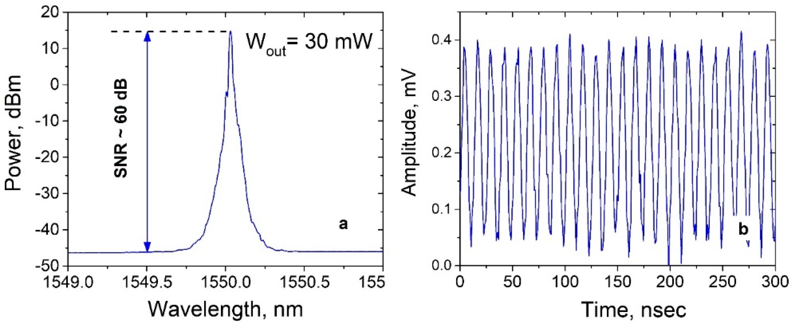
To increase the power of the measured signal, an optical amplifier (EDFA) was added to the setup, consisting of a 1.5 m active fiber Fibercore I-25 (980/125), which was also pumped by a 980 nm laser diode with power up to 500 mW through a WDM 980/1550. To suppress the influence of back reflection from the components, an isolator was added between the WDMs (Figure 2). To measure the spectral characteristics of the amplified signal, a Yokogawa AQ6370 optical spectrum analyzer (OSA) was used. The measured optical spectrum is shown in Figure 3a: the signal-to-noise ratio is ≈60 dB, and the generation linewidth corresponds to the resolution of OSA (20 pm). For a more precise measurement of the linewidth, the signal was launched to the Mach–Zehnder interferometer (MZI) through an optical connector. The signal power at the input of the interferometer was ~30 mW. One of the MZI arms contains a 4.6 km fiber, whereas another arm contains an acousto-optic modulator (AOM) driven by an Agilent 33250A waveform generator at a carrier frequency of 80 MHz. The beat signal (Figure 3b) was measured and analyzed by a Thorlabs DET08CFC photodiode and LeCroy WavePro 725Zi-A oscilloscope/5-GHz with FFT function, which allows the measurement of the waveform and RF spectra of the signal. Using the technique of processing the waveform of the beat signal, described in [18,19], the spectra of phase and frequency noises were obtained.

3.2. The Results

A comparison of the phase noise and frequency fluctuation power spectral density (PSD) obtained for a DFB laser in conventional and hybrid configurations is shown in Figure 4a,b. The measurements were carried out for a frequency range of more than 10 kHz, since for that, the influence of environmental and temperature noises is significantly reduced.
The frequency separation between the peaks in the spectra corresponds to the intermodal one for the 4.6 km long Mach–Zehnder interferometer, Δν ≈ 45 MHz. The dotted lines in Figure 4a correspond to the theoretically calculated phase noise values for the laser with the Lorentzian linewidths varied in the range of 0.1–10 kHz. For the frequency range above 100 kHz, there exists only white noise, characterized by S0 (that is, the first term of random frequency PSD expansion into a frequency power series), which determines the lower limit of the laser linewidth [20]: Δv = S0π. For a DFB laser without additional random DFB from SMF, the value of the instant generation linewidth determined by white noise is ≈15 Hz (Figure 4b—black color), which is in good agreement with the theoretical estimate. For the hybrid resonator the linewidth for frequencies above 100 kHz tends to be constant, which is determined by the electrical noise. The upper limit estimation of the generation linewidth, determined from the “bursts” of the signal above the level of electrical noise in the frequency range of 10–100 kHz, is about 0.1 Hz. Since the RIN peak completely “sinks” in the electrical noise (Figure 4b), it could be assumed that the white noise level (S0) for the composite resonator is much lower but its variation with frequency is similar. Taking this into account, we can estimate the generation linewidth from the corresponding correction of the noise curve above 100 kHz (see Figure 3b—blue color), which gives the estimated value of 10−3 Hz.
Thus, the value of the instantaneous linewidth of the hybrid DFB+RDFB laser configuration is estimated to be more than four orders of magnitude lower than that of a conventional DFB laser.
From the frequency fluctuation PSD spectrum, one can estimate the linewidth as a function of the observation time [21]. The linewidth is determined as follows:
FWHM = 8 ln 2 · A
where = 1 / T S ν f d f .
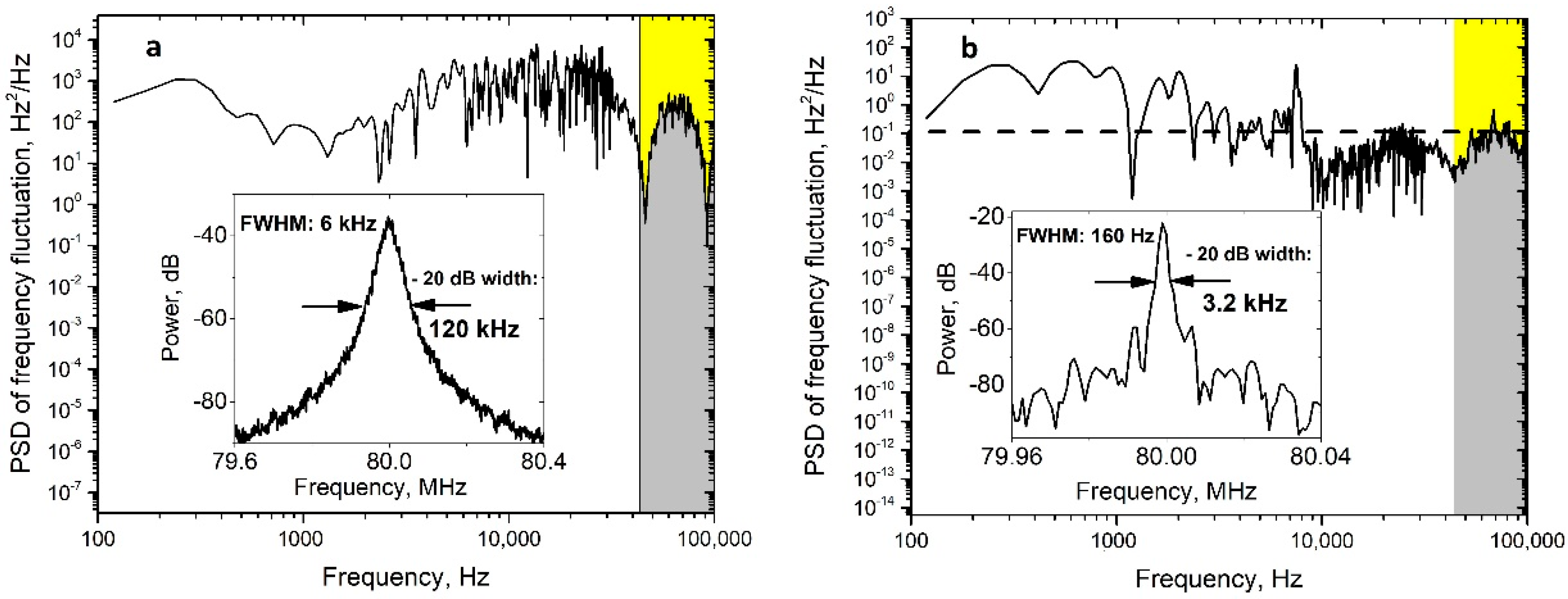
Figure 5 shows the frequency fluctuation PSD spectra for the DFB laser in conventional and hybrid configurations. As can be seen from (6), the linewidth increases as the lower limit of the integral decreases, or in the other words, as the observation time increases. This is due to the presence of 1/fα noise in the frequency fluctuation PSD [1]. Thus, the theory makes it possible to estimate the linewidth of the generation line at long times. Nevertheless, in [22], this model was applied at times of ~0.1 ms.
The value of ~100 kHz was taken as the upper limit of integration, since white noise S0 prevails in the range above 100 kHz. Similarly, for a delay line of 4.6 km (observation time is 23 μs), the width of the DFB laser line measured using the technique of [21] is 5.7 kHz (the integration limits are marked in yellow in Figure 5a), and the generation linewidth obtained using the self-delay heterodyne (SDH) technique [23] amounts to 120 kHz at −20 dB or 6 kHz at −3 dB. For a hybrid configuration, the linewidth measured using the technique of [21] is 150 Hz (the integration limits are marked in yellow in Figure 5b), while the values obtained by the SDH technique amount to 3.2 kHz at the level of –20 dB or 160 Hz at the level of −3 dB.

4. Discussion and Conclusions

Thus, the narrowing of the generation line of a DFB laser in a hybrid configuration with random DFB from 25 km SMF was demonstrated in this work: for instantaneous widths, the values obtained from the estimation based on phase-noise data processing differ by more than four orders of magnitude (from 15 Hz for conventional to 10–3 Hz for hybrid configuration). Such an extreme narrowing could not be observed directly from the experimental phase-noise data due to the limitation caused by electrical noise but may be estimated from the fitting of their frequency dependence. At the same time, the estimated limit obtained from the theoretical model for instantaneous linewidth narrowing factor is about 5∙106, which leaves room for further narrowing with the use of more precise measurement techniques. Significant narrowing was also observed at a longer-term scale by the self-delay heterodyne technique with delay line times of ≥10 μs: the linewidths for the DFB laser in conventional and hybrid configurations amount to about 6 kHz and 160 Hz, correspondingly.
One can also use shorter artificial Rayleigh fibers with enhanced back-scattering [11,12,13], which will enable a more compact design at the expense of a reduction in the linewidth narrowing factor.
In practice, the linewidth narrowing of Er-doped DFB fiber laser generating in telecommunication window around 1.55 micron allows the expansion of the application range of this source in such areas as coherent reflectometry, sensing, and telecommunications due to an increase in the coherence length, as well as for high-resolution spectroscopy, metrology, and frequency standards in this and other spectral ranges.

Funding

The study is supported by the state budget of IA&E (project No 121030500067-5).

Conflicts of Interest

The authors declare no conflict of interest.

References

  1. Cranch, G.A.; Flockhart, G.M.H.; Kirkendall, C.K. Distributed Feedback Fiber Laser Strain Sensors. IEEE Sens. J. 2008, 8, 1161–1172. [Google Scholar] [CrossRef]
  2. Kaminow, I.P.; Li, T.; Willner, A.E. Optical Fiber Telecommunications Volume VIA: Components and Subsystems; Optics and Photonics; Elsevier Science: Amsterdam, The Netherlands, 2013; ISBN 9780123972354. [Google Scholar]
  3. Fu, S.; Shi, W.; Feng, Y.; Zhang, L.; Yang, Z.; Xu, S.; Zhu, X.; Norwood, R.A.; Peyghambarian, N. Review of Recent Progress on Single-Frequency Fiber Lasers [Invited]. J. Opt. Soc. Am. B 2017, 34, A49–A62. [Google Scholar] [CrossRef]
  4. Turitsyn, S.K.; Babin, S.A.; El-Taher, A.E.; Harper, P.; Churkin, D.V.; Kablukov, S.I.; Ania-Castañón, J.D.; Karalekas, V.; Podivilov, E.V. Random Distributed Feedback Fibre Laser. Nat. Photonics 2010, 4, 231–235. [Google Scholar] [CrossRef]
  5. Wang, L.; Dong, X.; Shum, P.P.; Su, H. Tunable Erbium-Doped Fiber Laser Based on Random Distributed Feedback. IEEE Photonics J. 2014, 6. [Google Scholar] [CrossRef]
  6. Bulushev, A.G.; Dianov, E.M.; Kuznetsov, A.V.; Okhotnikov, O.G. Reduction in the Line Width of an Injection Laser by Resonant Rayleigh Scattering in a Fiber Ring Interferometer. Sov. J. Quantum Electron. 1989, 19, 479–481. [Google Scholar] [CrossRef]
  7. Yin, G.; Saxena, B.; Bao, X. Tunable Er-Doped Fiber Ring Laser with Single Longitudinal Mode Operation Based on Rayleigh Backscattering in Single Mode Fiber. Opt. Express 2011, 19, 25981–25989. [Google Scholar] [CrossRef] [PubMed]
  8. López-Mercado, C.A.; Spirin, V.V.; Bueno Escobedo, J.L.; Márquez Lucero, A.; Mégret, P.; Zolotovskii, I.O.; Fotiadi, A.A. Locking of the DFB Laser through Fiber Optic Resonator on Different Coupling Regimes. Opt. Commun. 2016, 359, 195–199. [Google Scholar] [CrossRef]
  9. Spirin, V.V.; Bueno Escobedo, J.L.; Korobko, D.A.; Mégret, P.; Fotiadi, A.A. Stabilizing DFB Laser Injection-Locked to an External Fiber-Optic Ring Resonator. Opt. Express 2020, 28, 478–484. [Google Scholar] [CrossRef]
  10. Xu, Y.; Zhang, L.; Chen, L.; Bao, X. Single-Mode SOA-Based 1kHz-Linewidth Dual-Wavelength Random Fiber Laser. Opt. Express 2017, 25, 15828–15837. [Google Scholar] [CrossRef]
  11. Dang, L.; Huang, L.; Li, Y.; Cao, Y.; Lan, T.; Iroegbu, P.I.; Cao, Z.; Mei, K.; Liang, L.; Fu, S.; et al. A Longitude-Purification Mechanism for Tunable Fiber Laser Based on Distributed Feedback. J. Light. Technol. 2022, 40, 206–214. [Google Scholar] [CrossRef]
  12. Popov, S.M.; Butov, O.V.; Bazakutsa, A.P.; Vyatkin, M.Y.; Chamorovskii, Y.K.; Fotiadi, A.A. Random lasing in a short Er-doped artificial Rayleigh fiber. Results Phys. 2020, 16, 102868. [Google Scholar] [CrossRef]
  13. Skvortsov, M.I.; Wolf, A.A.; Dostovalov, A.V.; Egorova, O.N.; Semjonov, S.L.; Babin, S.A. Narrow-Linewidth Er-Doped Fiber Lasers with Random Distributed Feedback Provided By Artificial Rayleigh Scattering. J. Light. Technol. 2022, 40, 1829–1835. [Google Scholar] [CrossRef]
  14. Schawlow, A.L.; Townes, C.H. Infrared and Optical Masers. Phys. Rev. 1958, 112, 1940–1949. [Google Scholar] [CrossRef]
  15. Henry, C. Theory of the Linewidth of Semiconductor Lasers. IEEE J. Quantum Electron. 1982, 18, 259–264. [Google Scholar] [CrossRef]
  16. Riehle, F. Frequency Standards: Basics and Applications; Wiley: Hoboken, NJ, USA, 2006; ISBN 9783527605958. [Google Scholar]
  17. Babin, S.A.; Churkin, D.V.; Ismagulov, A.E.; Kablukov, S.I.; Nikulin, M.A. Single Frequency Single Polarization DFB Fiber Laser. Laser Phys. Lett. 2007, 4, 428–432. [Google Scholar] [CrossRef]
  18. Fomiryakov, E.; Kharasov, D.; Nikitin, S.; Nanii, O.; Treshchikov, V. New Approach to Laser Characterization Using Delayed Self-Heterodyne Interferometry. J. Light. Technol. 2021, 39, 5191–5196. [Google Scholar] [CrossRef]
  19. Andel, N.; Yara, M.I.; Ohamed, M.; Ellahi, S.; Ouici, T.A.S.; Ardaillon, R.; Hilippe, P.; Ignoret, S. Time-Dependent Laser Linewidth: Beat-Note Digital Acquisition and Numerical Analysis. Opt. Exp. 2016, 24, 401–407. [Google Scholar] [CrossRef]
  20. Owens, D.K.; Weiss, R. Measurement of the Phase Fluctuations in a He–Ne Zeeman Laser. Rev. Sci. Instrum. 1974, 45, 1060–1062. [Google Scholar] [CrossRef]
  21. Di Domenico, G.; Schilt, S.; Thomann, P. Simple Approach to the Relation between Laser Frequency Noise and Laser Line Shape. Appl. Opt. 2010, 49, 4801–4807. [Google Scholar] [CrossRef]
  22. Xu, D.; Yang, F.; Chen, D.; Wei, F.; Cai, H.; Fang, Z.; Qu, R. Laser Phase and Frequency Noise Measurement by Michelson Interferometer Composed of a 3 x 3 Optical Fiber Coupler. Opt. Express 2015, 23, 22386–22393. [Google Scholar] [CrossRef]
  23. Okoshi, T.; Kikuchi, K.; Nakayama, A. Novel Method for High Resolution Measurement of Laser Output Spectrum. Electron. Lett. 1980, 16, 630–631. [Google Scholar] [CrossRef]
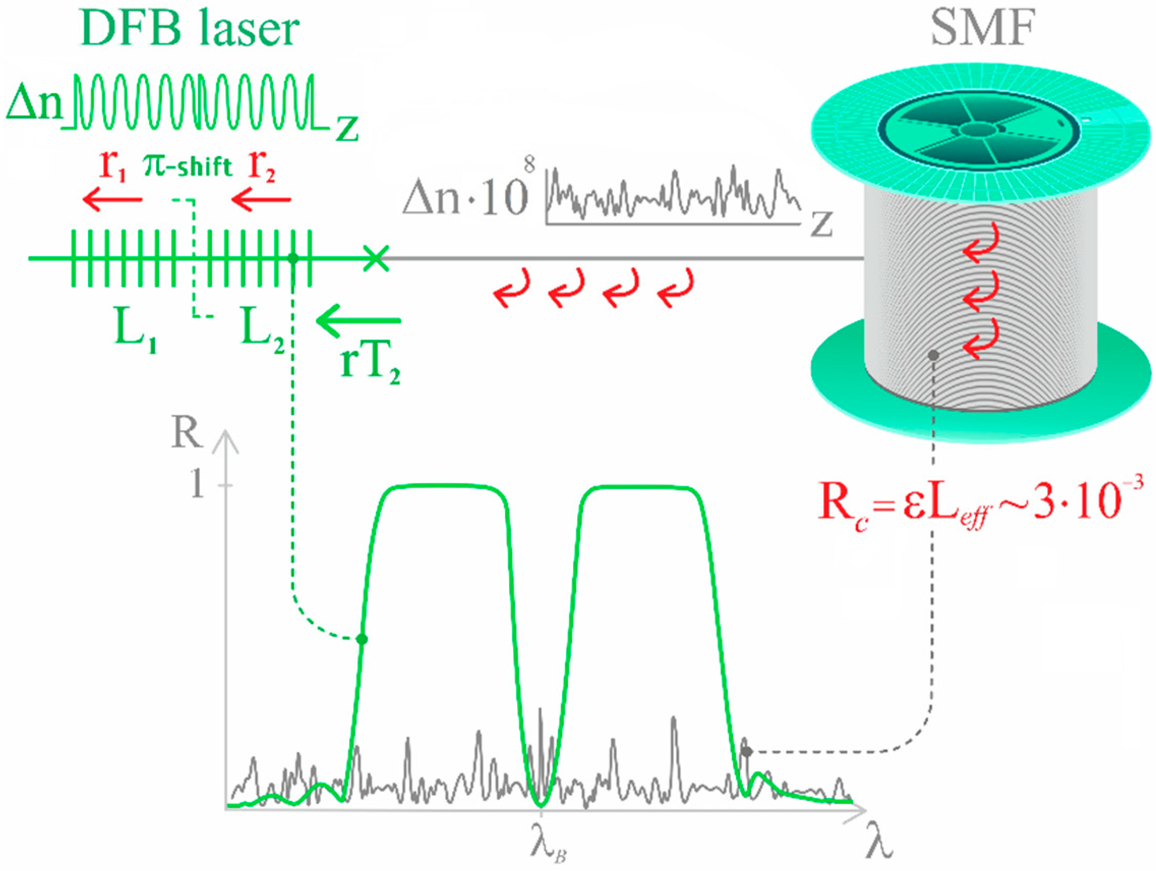
Figure 1. Basic scheme of hybrid configuration with DFB fiber laser and 25 km SMF spool.
Photonics 09 00590 g001
Figure 2. Scheme of the DFB and hybrid laser configurations and related measuring equipment.
Photonics 09 00590 g002
Figure 3. (a) Optical spectrum of the amplified signal at the input of MZI; (b) oscillogram of the beat signal.
Photonics 09 00590 g003
Figure 4. (a) Phase noise PSD obtained for a DFB laser in conventional (black) and hybrid (red) configurations. (b) Frequency fluctuation PSD obtained for a DFB laser in conventional (black) and hybrid (red) configurations and estimation above 100 kHz (blue).
Photonics 09 00590 g004
Figure 5. (a) Frequency noise PSD obtained for DFB laser in conventional (a) and hybrid (b) configuration. On the insets: RF beating spectra obtained by heterodyne technique.
Photonics 09 00590 g005
Publisher’s Note: MDPI stays neutral with regard to jurisdictional claims in published maps and institutional affiliations.