Article

Hydrothermally Synthesized Fluorine Added O3-NaFe1-xMgxO2 Cathodes for Sodium Ion Batteries

1
Department of Physics, College of Science, King Faisal University, Al-Ahsa 31982, Saudi Arabia
2
Department of Chemistry, College of Science, Princess Nourah Bint Abdulrahman University, Riyadh 11671, Saudi Arabia
3
Department of Basic Sciences, Preparatory Year Deanship, King Faisal University, Al-Ahsa 31982, Saudi Arabia
4
Laboratory of Tissue/Organ Bioengineering and BioMEMS, Organ Transplant Centre of Excellence, Transplantation Research & Innovation (Dpt)-R, King Faisal Specialist Hospital and Research Centre, Riyadh 11211, Saudi Arabia
5
Department of Chemistry, Khalifa University, Abu Dhabi P.O. Box 127788, United Arab Emirates
*
Authors to whom correspondence should be addressed.
Inorganics 2023, 11(1), 37; https://doi.org/10.3390/inorganics11010037
Submission received: 16 November 2022 / Revised: 16 December 2022 / Accepted: 21 December 2022 / Published: 10 January 2023

Abstract

:
The development and study of Na ion batteries are expanding. This study employs the hydrothermal technique to produce single-phase, well-crystallized, fluorine-added O3-type NaFe1-xMgxO2. Using XRD, FESEM, and HRTEM, the sample’s phase structure and morphological information were characterized. Initially, without adding fluorine the electrode suffers from poor stability at high voltage ranges and also during long-term cycling. So, fluorine was added to the structure and the electrochemical performance of the material was greatly increased. The electrochemical performance of O3-type positive electrode materials for rechargeable Na ion batteries is evaluated. The capacity of fluorine-added O3-type NaFe1-xMgxO2 is approximately 163 mAh g−1 (50 mA g−1). Adding fluorine to the host structure increases the stability of the electrode, leading to improved electrochemical performance during long-term cycling. The electrochemical results indicate that fluorine-added O3-type NaFe1-xMgxO2 cathode material for cost-effective and environmentally friendly sodium-ion batteries is promising. Fluorine-based electrodes will be a future for Na ion energy storage devices

1. Introduction

Sodium-ion batteries (SIBs) with low cost and abundant sodium supplies are a potential alternative to lithium-ion batteries (LIBs) for large-scale energy storage [1,2,3,4,5,6,7]. Since the cathode material is a crucial part of the SIB, it has a significant impact on the battery’s electrochemical performance. Due to Na+’s larger size relative to Li+, cathode materials must have efficient Na+ diffusion pathways and strong structural stability. Due to their low cost of production and high theoretical specific capacities [1,2,5,8,9,10], layered Na-containing transition metal oxides have garnered a lot of attention as potential cathode materials for solid oxide fuel cells. NaxMeO2 (Me, transition metal) has a number of different layered polymorphs, the majority of which may be categorized into O- and P-type stacking layered structures, respectively [11].
O3-NaFeO2 is one of the layered Na-containing transition metal oxides that has been given serious consideration as a cathode material because of its abundant, nontoxic, and low-cost iron source. Importantly, many conventional layered cathode materials can be viewed as O3-NaFeO2 derivatives with a space group of R-3 m. This includes materials like LiCoO2 [12], LiNi0.5Mn0.5O2 [13], LiNi1/3Mn1/3Co1/3O2 [14], and NaxMeO2 [15,16,17,18]. Electrochemically inactive NaFeO2 is easy to generate from the wrong choice of Fe and Na sources, making the synthesis of NaFeO2 a challenge in general [19]. The less reactive starting material Fe2O3 was used by Takeda et al. [20] in a topotactic reaction to produce -NaFeO2, however, the use of Na2O2 as the sodium source and the need for an inert gas atmosphere negated any cost savings. In a recent hydrothermal reaction, NaFeO2 was synthesized from FeOOH and NaOH. However, this hydrothermal reaction is problematic for cost-effective and large-scale production since it requires ultrahigh NaOH concentration (45 M) and subsequent cleaning.
There has been a lot of work in recent years to develop excellent positive electrode materials with high reversible capacity, rapid insertion/extraction of Na ions, and good cycle stability because cathode materials play such a large role in determining energy density and cost. Layered oxides, polyanionic frameworks, hexacyanoferrates, and organic compounds are only some of the many substances studied as potential cathode materials. NaxTMO2 layered oxides (0 × 1; TM Fe, Cr, Co, Mn, Ni, V, Cu, and mixes thereof) are one of the most promising groups of cathode materials for SIBs [21,22,23,24] due to their high capacities, sufficient operating potentials, and facile and scalable synthesis. These findings suggest that Na-intercalation electrochemistry is substantially different from Li-intercalation electrochemistry, presenting opportunities for developing cutting-edge materials and discovering innovative Na storage mechanisms.
In this present work, O3-NaFe1-xMgxO2 performance was enhanced by adding fluorine into the structure by the conventional hydrothermal method. The main purpose of the present work is to enhance the stability of the material at higher voltage and to increase the cyclic performance of the electrode. Previously, O3-NaFe1-xMgxO2 was reported by J. Jayachitra et al. [25] in which the capacity fade was observed at a higher range due to ion decomposition in the electrolyte. Based on the previous results in this present work we added fluorine to increase the voltage range and the stability of the material.

2. Experimental Procedure

Electrode materials of O3-NaFe1-xMgxO2F with varying ratios (X = 0.1, 0.2, 0.4, and 0.5) were manufactured using a conventional hydrothermal process, as shown in Figure 1. We bought everything we needed from Sigma Aldrich and used it as-is. Sodium acetate, iron acetate, magnesium acetate, and sodium fluoride were each dissolved in 50 cc of DI water and stirred for many hours until the desired stoichiometry was reached. To bring the solution’s PH up to 8, some NaOH was diluted into it. After stirring the solution for 4 h. A Teflon-lined autoclave was used to keep the solution at 160 °C for 12 h. Once the sample reached room temperature, it was collected and cleaned multiple times with ethanol and distilled water to remove any remaining contaminants. After washing, a sample was dried in a 100 °C oven for 10 h. After being prepared, the sample was precalcined at 300 °C and calcined at 650 °C for 6 h. The number assigned to the finished product was NMFF 1. The same method was applied to different ratios, which were given the NMFF1 (O3-NaFe0.9Mg0.1O2F (x = 0.1), NMFF2(O3-NaFe0.8Mg0.2O2F (x = 0.2)), NMFF3(O3-NaFe0.6Mg0.4O2F (x = 0.4)), and NMFF4(O3-NaFe0.5Mg0.5O2F (x = 0.5)) designations.

2.1. Process for Electrochemical Study

For the electrochemical examination, the CR2032 coin cells were prepared in a glove box(GS Glove box) with an argon atmosphere. The prepared sample served as the cathode, while pure Na metal served as the anode and polypropylene served as the separator. Combining EC and DEC (1:1 v/v) with 1M NaClO4 produced the electrolyte. Cathodes were produced by combining 2.5 g of the active ingredient with 0.5 g of ketjen black and 0.5 mg of teflonized acetylene black (TAB-2) in the ratio of 80:20:20. To create coin cells, the produced mixture was applied to a stainless-steel current collector and dried at 160 °C in a vacuum oven. The loading mass of the material is 2.5 g. Utilizing an Arbin BT-2000 battery tester, charge-discharge cycles were performed at a variety of voltages and current densities (50–2000 mAg−1). An electrochemical analyzer was utilized for EIS analysis (SP-150, BioLogic, Seyssinet-Pariset, France).

2.2. Materials Characterization

After conducting, a structural study with X-ray diffraction (XRD Cu K radiation, Rint 1000, Rigaku Tokyo, Japan) in the range 2 of 10–90°), the lattice parameters and crystal values were determined with Rietveld Refinement in Full-Proof software. Utilizing a Hitachi scanning electron microscope and an HR transmission electron microscope, the surface’s atomic composition, and morphology were determined (HRTEM, JEOL Ltd. Tokyo Japan). Surface composition and elemental valence were analyzed by Thermo ESCALAB250Xi X-ray photoelectron spectrometer (XPS) (Thermo Fisher Scientific Inc., Waltham, MA, USA) with the monochromatic Al Ka X-ray source.

3. Results and Discussion

3.1. XRD and Rietveld Analysis

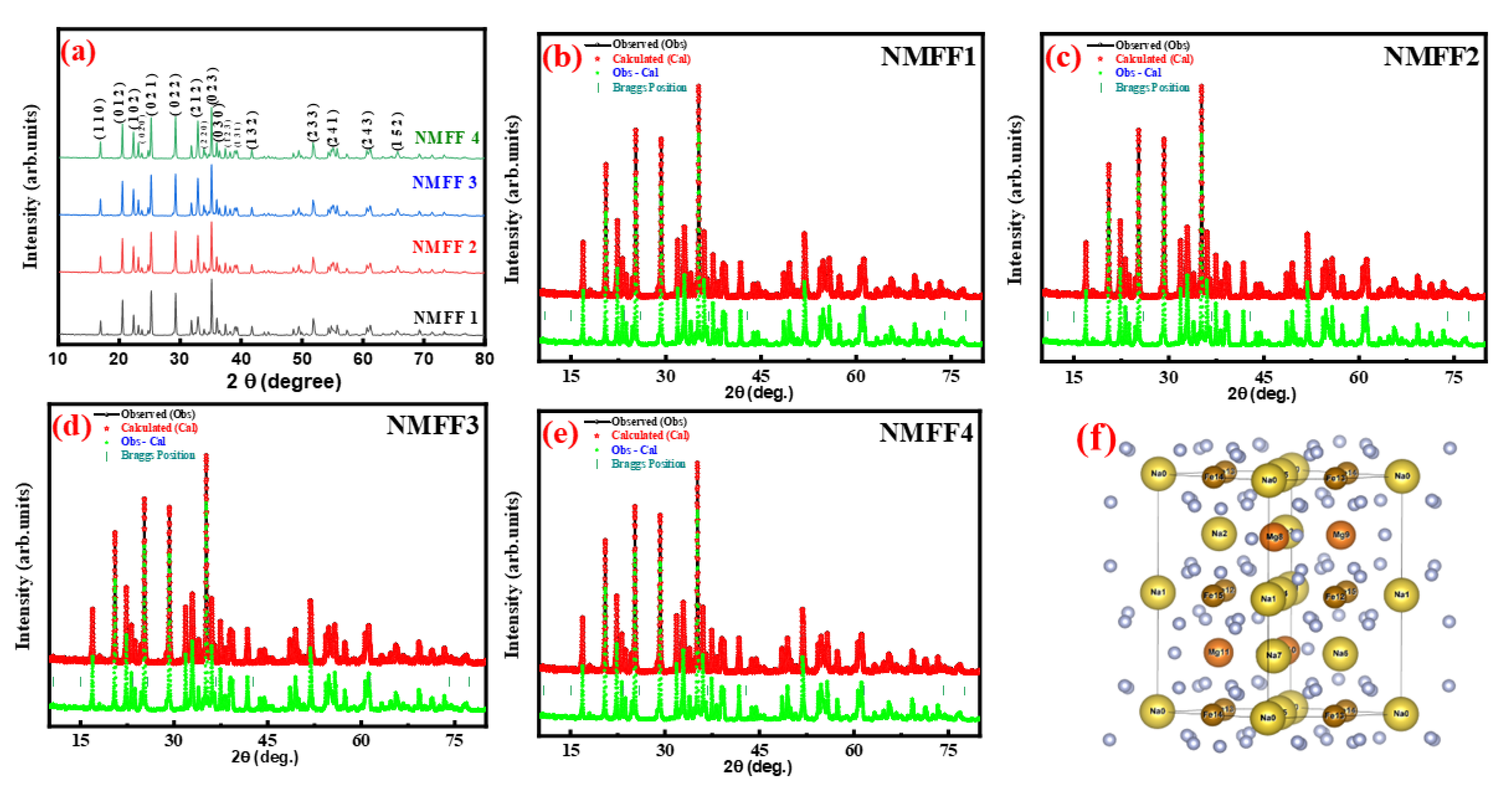
The phase purity and crystal parameters were analyzed using XRD and Rietveld analysis. Figure 2 shows the prepared samples’ XRD and Rietveld patterns. The samples were prepared at different ratios (x = 0.1, 0.2, 0.4, and 0.5). Compared with the previous studies, O3-NaFe1-xMgxO2F, all the peaks were indexed matches the standard values (Figure 2a). In the present work, the addition of fluorine was confirmed by the presence of a peak at 180, confirming the presence of fluorine in the prepared samples. The presence of fluorine greatly influences electron transport at higher voltages during the electrochemical performance. The well-indexed peak confirms the presence of the crystalline phase, and it is evident that there is no other impurity peak observed in the prepared samples. The reitveld analysis helps us to understand more about crystal structure and phase parameters. To further analyze the phase structure and change in cell parameters on doping with different ratios, we analyzed by using Rietveld refinement analysis (Figure 2b–e). The Rietveld patterns also confirm the sample’s crystalline nature. On analyzing further, the change in size was observed during refinement, which is due to adding Mg in ratios on the core-shell of O3-NaFe1-xMgxO2F. The space group P4/mmm is displayed by the NaFe1-xMgxO2F. After careful calculation, the refined crystal structure has the dimensions (a, b, c) of a = 8.5167, 8.5187, and 8.5336 angstroms. The low Rwp and Rp values indicate that NaFe1-xMgxO2F was the form in which the O3 layered oxide was synthesized. The oxygen was twisted in a cubic close-packed array, while the transition metals (Fe/Mg) and Na occupied two octahedral positions (3a and 3b), respectively. The computed Fe/Mg-O and Na-O interatomic lengths are 1.66 and 2.26, respectively. Changes in crystal characteristics were detected, albeit only slightly [26,27,28]. This was attributed to an increase in the Mg ratio. To confirms the element presence ICP analysis was taken and the results are tabulated in Table 1.

3.2. FESEM Analysis

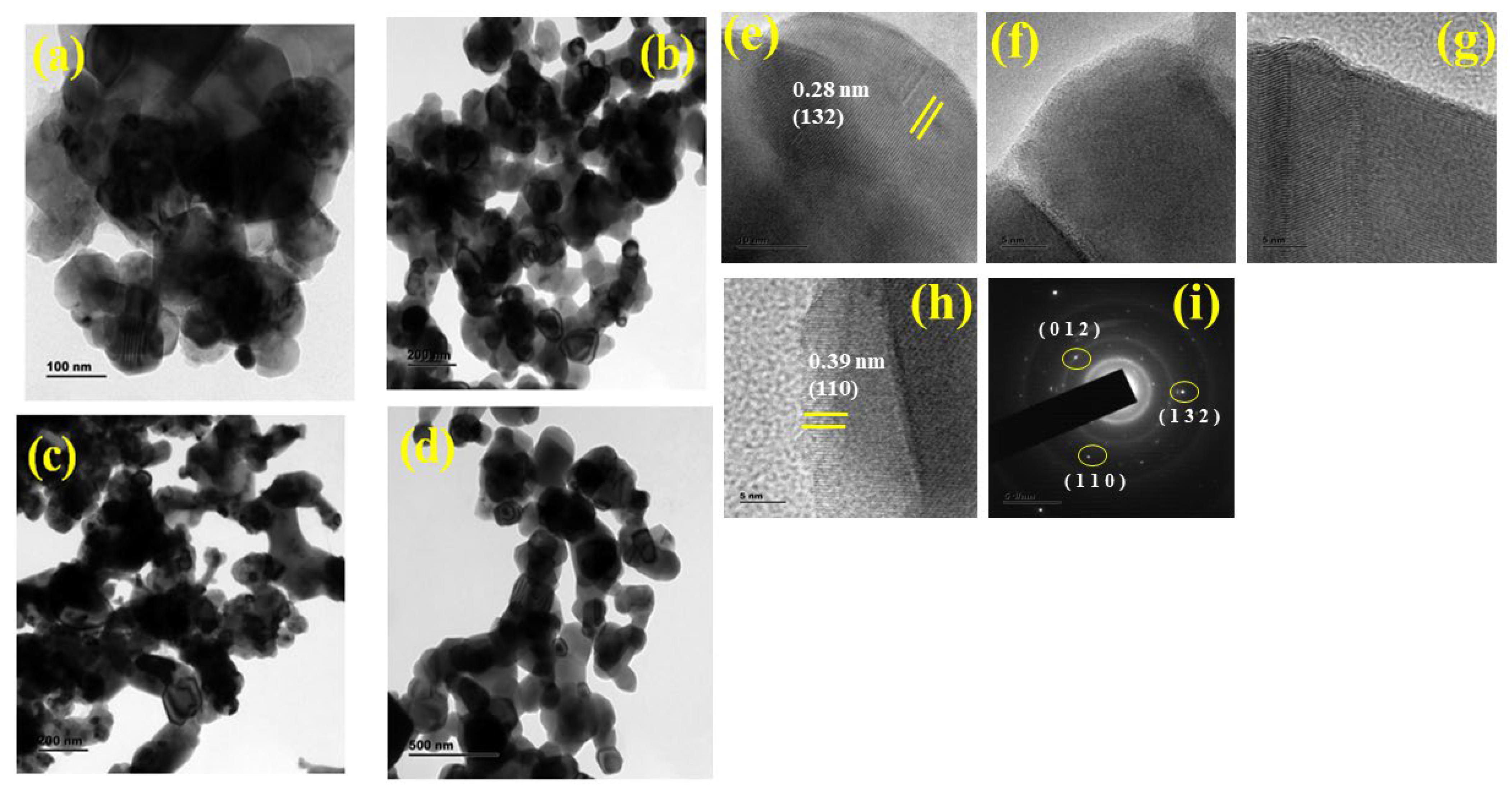
The FESEM and HRTEM analysis was performed to analyze the samples’ morphological natures. Figure 3 shows the FESEM and HRTEM images of the prepared samples. Figure 3a shows the result of the NMFF1 samples. The sample’s morphological nature was slightly changed compared to NaFe1-xMgxO2 due to adding fluorine to the structure. On the surface, and in between the layers of NaFe1-xMgxO2, polished thin sheet-like structures are formed, which may be due to adding fluorine to the core structure. On increasing the ratio from 0.1 to 0.2, the changes in the particle’s size were clearly observed in Figure 3b NMFF2 the polished thin sheets are clearly increased in size on the ratios of Mg into the Fe ions. The fluorine and Mg clearly show their presence in the morphological structure. The aim of the present work is to introduce fluorine in between O3 layers of NaFe1-xMgxO2 and it is confirmed by analyzing the prepared samples by FESEM images. The thin layer of the sheet was clearly shown in between the particles. On seeing the images in Figure 3c,d, the increase in the particle’s size was clearly observed upon increasing the doping ratios. The increase in particle size was in the range of 22 nm (NMFF1)–45 nm (NMFF4). The EDS spectrum of the prepared sample was shown in Figure 3e. The changes in size and addition of fluorine between the layers of NaFe1-xMgxO2 enhance the sample’s morphological structure and also confirms the refinement patterns [29,30]. Figure 4a–d shows the HRTEM images of the prepared samples. The HRTEM results also confirm and match the FESEM results. Adding fluorine to the core NaFe1-xMgxO2, we may see, on the top, some thin sheets with fringes that may be due to the presence of fluorine on the samples. The increase in doping of Mg with different ratios results in an increase in the particle’s size, as is confirmed on the HRTEM images. Figure 4e–i shows the clear fringes on examining the inner portion of the prepared sample. On seeing the HRTEM images, the sample’s pure crystalline nature was achieved.

3.3. XPS Analysis

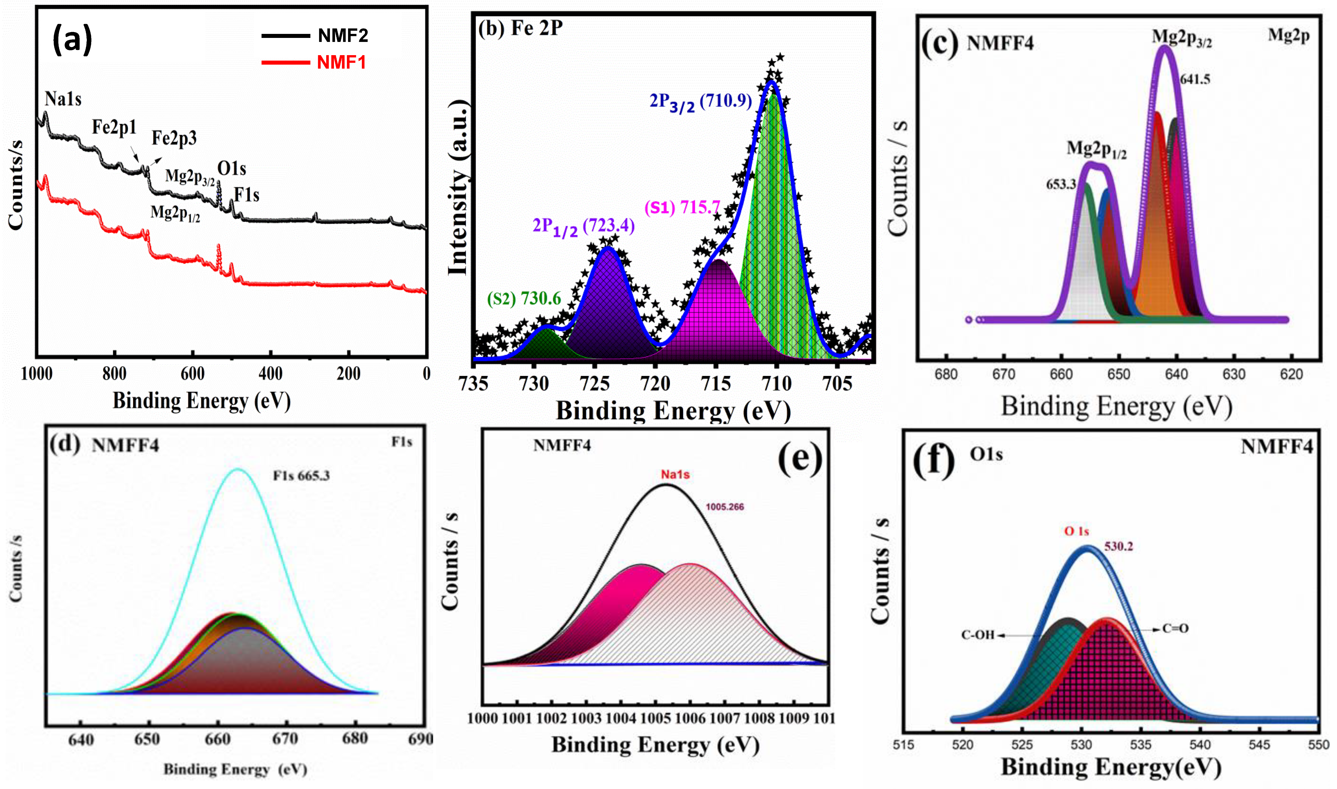
The XPS examination was carried out so that we could gain an understanding of the chemical composition of the samples as well as their oxidation state. The XPS spectra of the samples that were prepared are presented in Figure 5a. The survey spectrum reveals that changing the number of doping results in a spectrum that is identical for all of the samples. This indicates that changing the material’s composition does not result in the formation of any extra composition. The fact that peaks were generated at 1005.25, 710.2, 653, 665.3, and 530 provides evidence for the presence of Na, Fe, Mg, F, and O. The spectrum of Fe2p after it has been deconvoluted is seen in Figure 5b. The Fe2p peaks were broken up into four distinct peaks located at 710.2, 723.4, 715.6, and 730.9. The spectra recorded at 710.2 and 723.4 eV, respectively, correspond to the elements Fe2p1 and Fe2p3 [24]. Another peak can be found at 715, while 730 represents the satellite peak. The Na-1s spectra are seen in Figure 5e. The fact that the binding energy came was 1005.7 eV substantiates the existence of Na-1s. The presence of a peak at 641 and 653 angstroms provides evidence for the chemical composition of Mg in the samples that have been prepared (Figure 5c). The oxidation status of F1s can be verified by the convoluted peak located at 665.3. Additionally, the chemical composition, as well as the oxidation state of the produced samples, are validated by the XPS spectra [31,32,33]. The deconvoluted spectrum of oxygen was displayed in Figure 5f.

3.4. BET Analysis

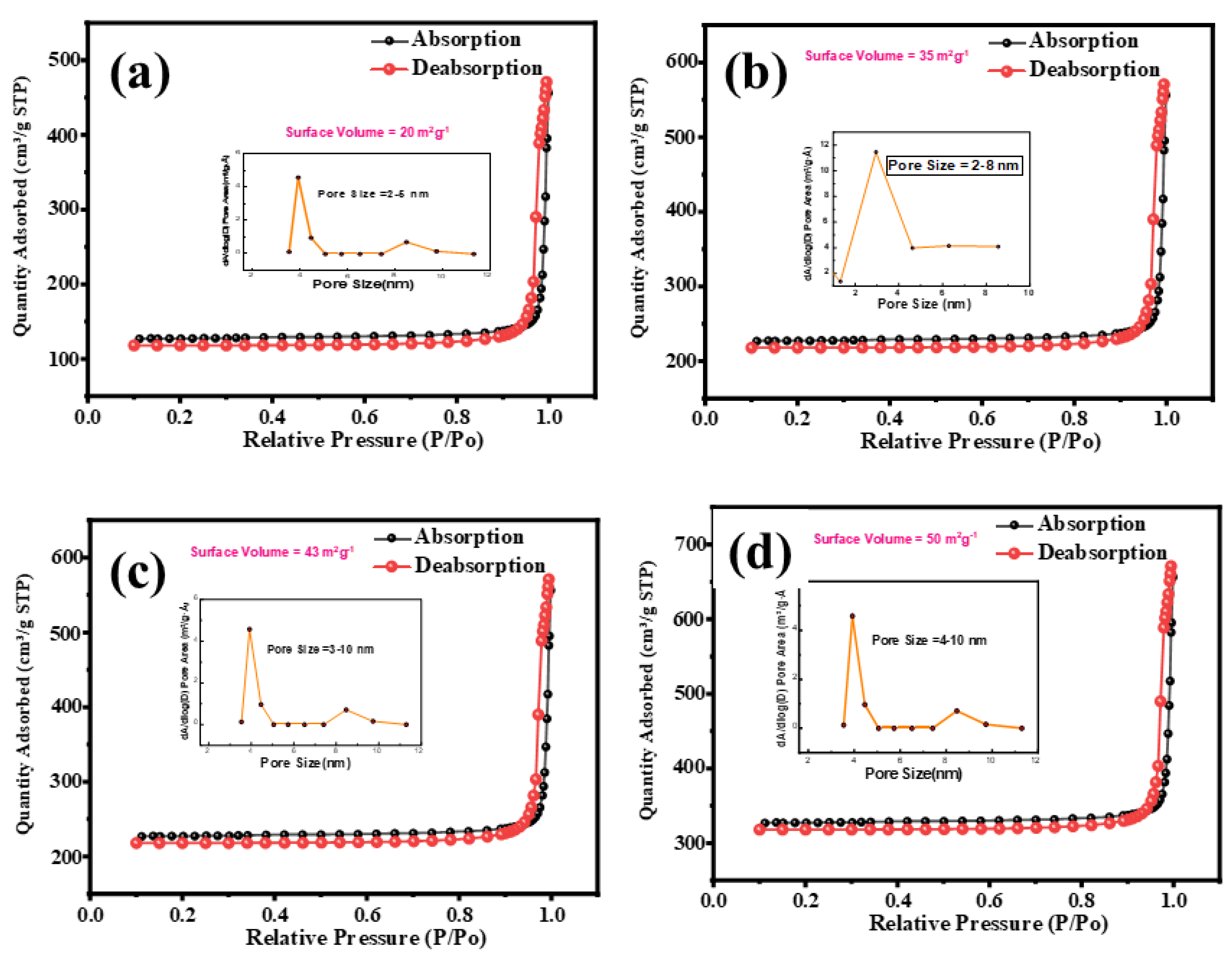
The N2 adsorption and pore-size distribution curve of the mesoporous NMFF1, NMFF2, NMFF3, NMFF4 were shown in Figure 6 with an inset of pore-size distribution. The samples show type IV isotherms in Figure 6 which confirms the mesoporous nature and the H4 type hysteresis loop shows the slit-shaped pores. As shown in Figure 6a, the pure NMFF1 sample shows a sharp pore-size distribution of 3.3 nm with a surface area of about 60.2 m2 g−1. On the other hand, NMFF2,NMFF3,NMFF4 samples deliver surface area of about 63 m2 g−1 (NMFF2), 69.5 m2 g−1 (NMFF3), 74 m2 g−1 (NMFF3) with an average pore diameter of 3 nm (NMFF2), 2.8 nm (NMFF3) and 2.2 nm (NMFF4) respectively. It is well known that mesoporous nature with high surface area and a pore size ranging from 2–5 nm greatly promotes the electroactive sites and shortens the diffusion paths for charge transports, which improves the electrochemical performance of the prepared samples.

3.5. Electrochemical Analysis

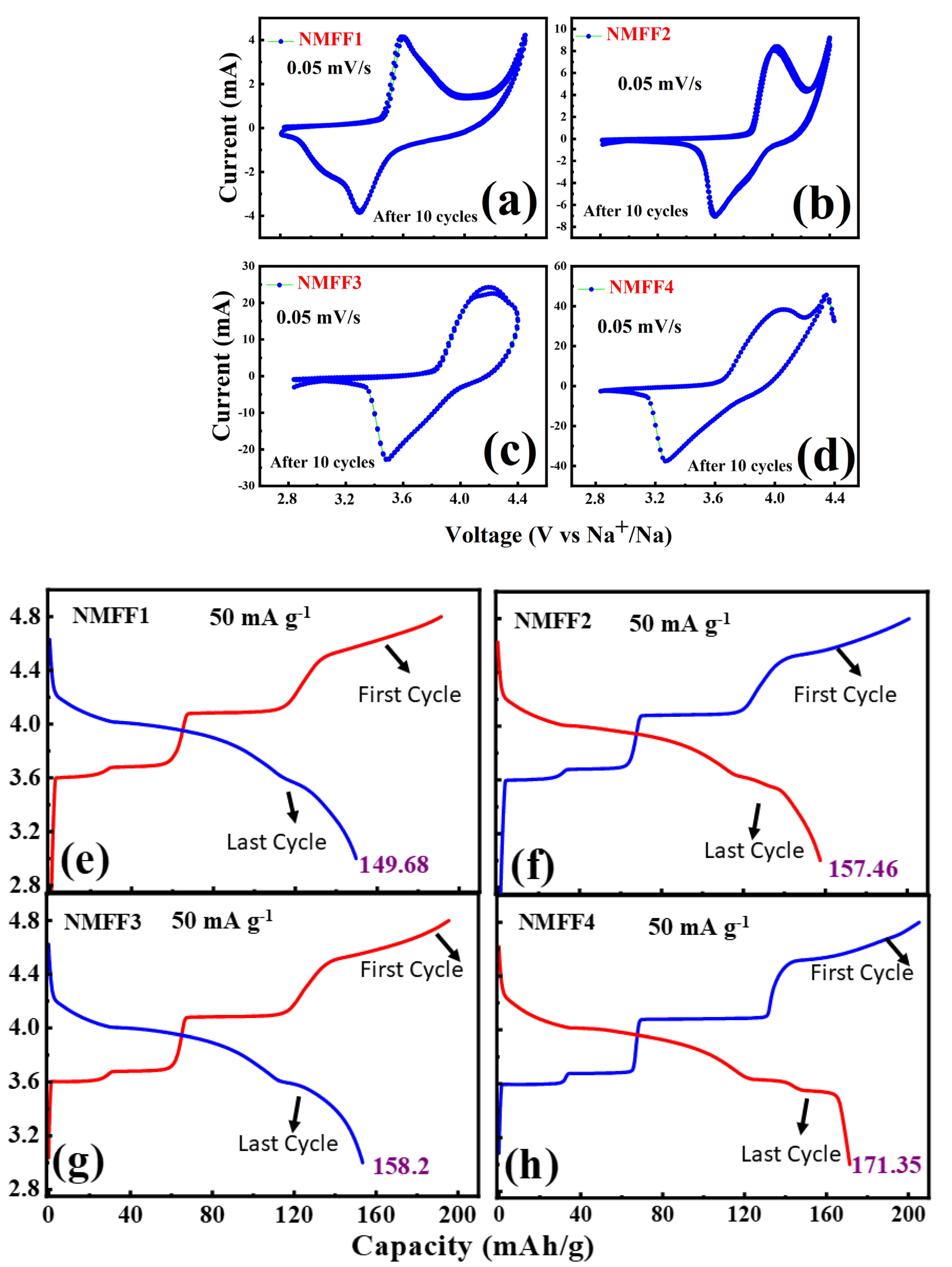
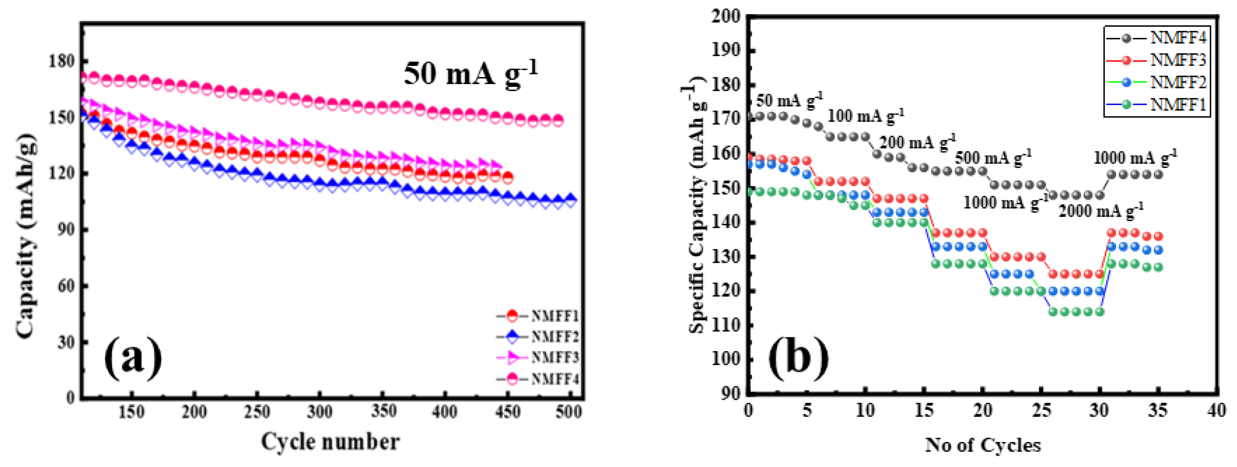
The electrochemical analysis of the prepared electrode was analyzed using a battery tester at different conditions. Figure 7a–d’s CV pattern of the prepared samples. All of the prepared samples deliver excellent cyclic and reversible nature, which is considered an important tool for rechargeable energy storage. On comparing with the area of the curve, NMFF4 shows excellent electrochemical performance. The enhanced performance of NMFF4 is due to the active participation of F ions during ion transport between the electrodes, which greatly increases the material’s stability. Figure 7e–h shows the samples’ charge/discharge performances. The discharge profile was performed at the voltage range of 2.5 to 4.8 V. The increase in discharge voltage was observed in comparison with the previous work NaFe1-xMgxO2 [25]. The increase in discharge voltage is due to adding fluorine to the core structure of NaFe1-xMgxO2. The basic nature and aim of adding fluorine to the electrode are to stabilize the electrode at higher voltages and smooth the transport of electrons, even at higher operating voltages. To investigate the cyclic performance of the electrode, the testing was carried out for 500 cycles (Figure 8a). The NMFF4 samples show excellent cyclic stability compared to other electrodes, with a capacity retention of about 89–90% after 100 cycles. On the other hand, capacity retention is about 85% (NMFF3), 80% (NMFF2), and 75% (NMFF1).
The discharge capacity of NaFe1-xMgxO2F (NMFF1) is about 148.8 mAh g−1. The increase in discharge capacity was observed upon comparing with NaFe1-xMgxO2 results [34,35]. The increase in capacity is due to adding fluorine. The facts behind this fluorine share the position with the sites of Mg, which creates more active sites for electron transport [36]. On increasing the doping ratios (x = 0.1,0.2, 0.4, 0.5), the discharge capacity starts increasing compared to NMFF1(x = 0.1), when the delivered discharge capacity is about 157.68 mAh g−1 (NMFF2 (x = 0.2)), 159.2 mAh g−1 (NMFF3(x = 0.4)), and 171.35 mAh g−1 (NMFF4 (x = 0.5)), respectively. The addition of fluorine to the active material (NaFe1-xMgxO2). The fluorine creates more active sites for electron transport, even at high operating voltages. Figure 8b shows the rate performance of the electrode materials at different current densities (50 mA g−1–2000 mA g−1). When compared with the four electrodes, NMFF4 delivers a high capacity of 171.3 mAh g−1 (50 mA g−1) and 150 mAh g−1 (2000 mA g−1). Interestingly, adding fluorine greatly influences the electrode’s electrochemical performance. During the electrochemical performance at different current densities, the capacity fade was observed in the middle around 3–3.5 V. The initial capacity fade is due to the migration of the Fe ion into the Na layer, which results in the capacity fade at higher operating voltages. The migration of Fe ions into the Na layer was greatly stabilized by adding Mg into the Fe layer at different ratios. The Mg ion greatly stabilizes the migration of ions into the Na layer, which motivates the Fe ions to actively participate in the electrochemical performance. Even though the Mg ion reduces the migration of Fe ions, the capacity fade was observed during long-term cycling performances. This is due to the loss of ions into the electrolyte at a higher voltage. On seeing the results of NaFe1-xMgxO2, the capacity fade issues were noticed when the electrode was cycled at higher voltages and also during the long-term cycling process. To rectify these issues, we decided to add fluorine to NaFe1-xMgxO2 to reduce the capacity fade during long-term cycling. Interestingly, we observed positive electrochemical results, as adding fluorine creates a strong SEI layer and greatly enhances the electrode’s performance. The SEI layer acts as a protective layer and reduces the contact between the electrode and electrolyte. This promotes the smooth transport of electrons and reduces ion decomposition during cycling. On increasing the current density, the capacity seems to be decreased. The respective specific capacity is about 159.2 mAh g−1 (NMFF3), 157.68 mAh g−1 (NMFF2), and 149.68 mAh g−1 (NMFF1), respectively. Even after cycling to check the reversibility nature of the electrode, the electrode was again performed at 400 mA g−1 and delivered a capacity of about 151 mAh g−1. This performance shows the reversible nature and stability of the electrode at different conditions [37].
To investigate the cyclic performance of the electrode, the testing was carried out for 500 cycles as shown in Figure 9. The NMFF4 samples show excellent cyclic stability compared to other electrodes, with a capacity retention of about 89–90% after 100 cycles. On the other hand, capacity retention is about 85% (NMFF3), 80% (NMFF2), and 75% (NMFF1).
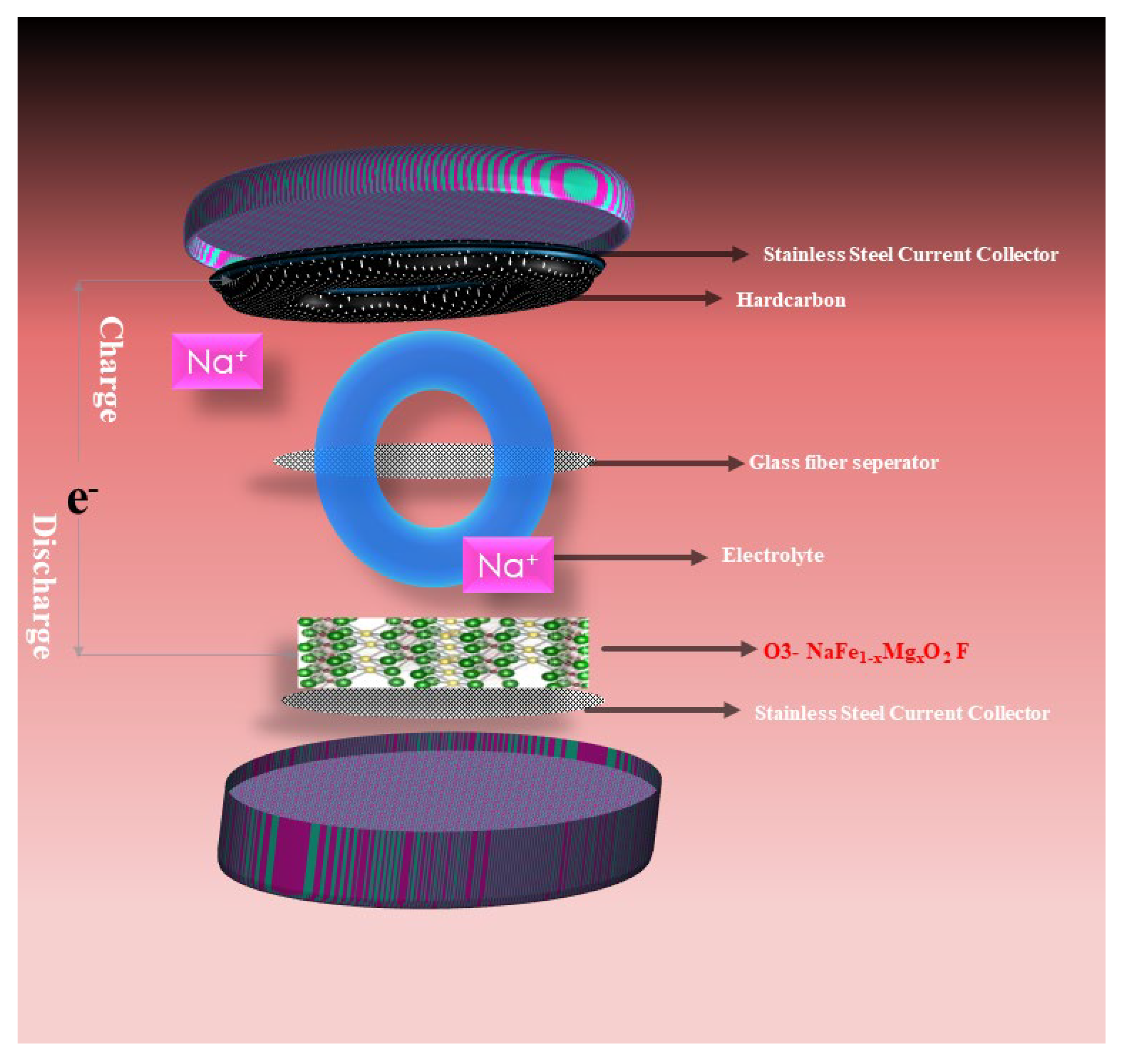
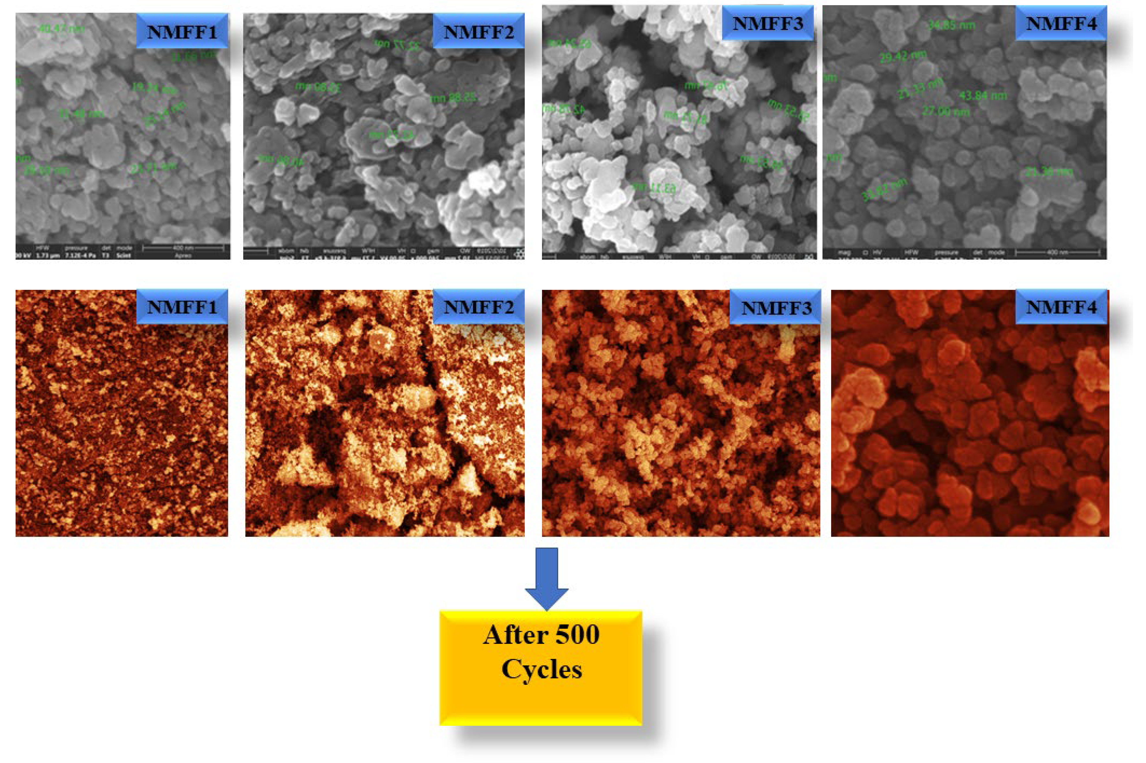
Figure 9 shows the electrodes’ arrangements in a coin cell. To check the stability of the material after 500 cycles. The samples were separated from the coin cell and examined through FESEM to observe the sample’s morphological changes. The FESEM images of the samples, taken after 500 cycles, are shown in Figure 10. On seeing the FESEM images, after 500 cycles in NMFF1, the ions completely decomposed, and there are no active sites for electron transport, resulting in the amorphous nature of morphology that was observed in NMFF1 after 500 cycles. However, the morphology nature of NMFF2 and NMFF3 holds good for almost 400 cycles and then the ion decomposed. On the other hand, the morphological nature of the sample does not change in NMFF4, which shows that NMFF4 holds its nature stable even after 500 cycles. Only 5–8% of ions decompose after 500 cycles, which shows that 90% of active sites are available for electron transport even after 500 cycles. From this result, we can confirm that the NMFF4 sample delivers good electrochemical performance with high stability nature.
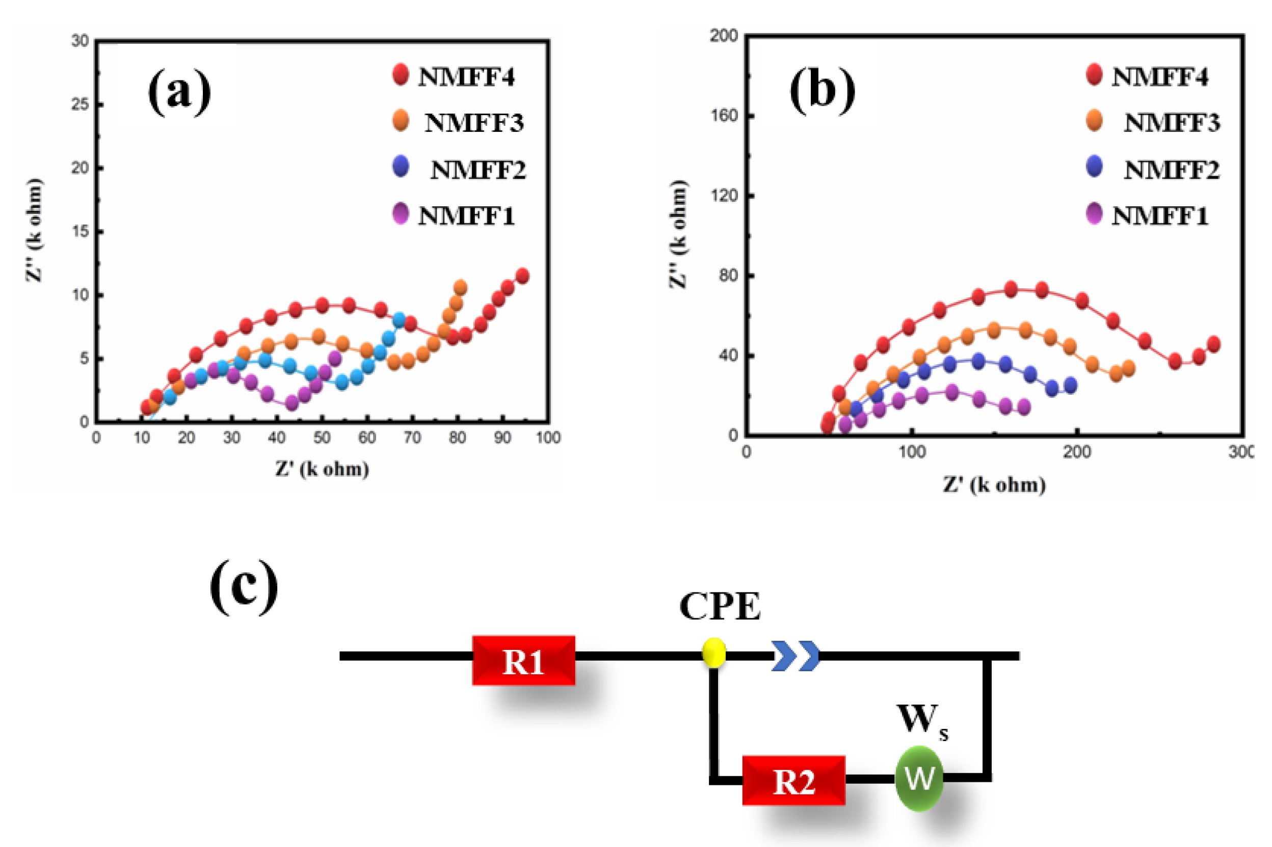
To determine the electrode’s kinetic performance, EIS analysis was performed for the electrode at different conditions as shown in Table 2. The fluorine-added NaFe1-xMgxO2 (NMFF4) shows the large semicircle at the high-frequency region followed by a quasi semi-circle at medium frequency followed by a straight line, which shows the conductive nature of the sample even at a low frequency.
The sample’s high conductive nature was observed because of the smooth transport of the ion and active participation of Fe and Mg ions into the electrolyte [38,39]. The fluorine reduces the electron loss at higher operating voltages and increases the stability of the material. When compared with NMFF4, the other electrodes possess a less conductive nature because of Fe migration and ion decomposition into the electrolyte. At a low ratio of Mg doping, despite active fluorine participation, low doping cannot stabilize the Fe ions during long-term cycling [40,41] (Figure 11a–c). After 500 cycles, an EIS was performed to analyze the stability of the electrode. The reduction in the intensity of the semi-circle at a higher frequency may be due to the loss of the Fe ion into the electrolyte. On the other hand, the NMFF4 shows good results, even after 500 cycles when compared with the remaining electrodes. This is due to the smooth transport of ions and less electrolyte decomposition. The impedance spectra confirm the CV results. All the samples show good electrochemical performance, but NMFF4 shows a higher stability rate compared to the other three samples which is also mentioned and observed in the cv curved of the prepared samples. The electrochemical results conclude that the NMFF4 sample shows excellent electrochemical performance compared to other electrodes. The comparison with the previous reports is listed in Table 3.

4. Conclusions

The O3- NaFe1-xMgxO2F sample was prepared using the hydrothermal method. The phase and crystal nature of the sample was confirmed by using XRD and refinement results. The FESEM results establish that the fluorine shows thin polished sheets on the surface and between the layers of NaFe1-xMgxO2, which greatly influences the performance of the electrode during battery testing. A high surface area was achieved for NMFF4 which greatly promotes electrochemical performance. The addition of fluorine increases the voltage compared to the previous works and stabilizes the material even at a higher voltage. The NaFe1-xMgxO2F (x = 0.5) delivers the highest capacity of about 171.35 mAh g−1 (50 mA g−1). The electrochemical results show excellent electrodes for large-scale energy storage applications for NIB batteries.

Author Contributions

Conceptualization, M.W.A. and S.S.; Data curation, A.Y. and S.S; Formal analysis, A.B., A.Y. and T.A.M.; Funding acquisition, M.W.A.; Investigation, A.B. and I.N.; Methodology, A.Y. and T.A.M.; Project administration, M.W.A.; Resources, M.W.A. and A.Y.; Software, A.B. and I.N.; Supervision, M.W.A.; Visualization, S.S.; Writing—original draft, M.W.A. and T.A.M.; Writing—review & editing, M.W.A. and I.N. All authors have read and agreed to the published version of the manuscript.

Funding

The authors extend their appreciation to the deputyship for research and Innovation, Ministry of education in Saudi Arabia for funding this research work through the project number INST170.

Institutional Review Board Statement

Not applicable.

Informed Consent Statement

Not applicable.

Data Availability Statement

Not applicable.

Acknowledgments

The authors extend their appreciation to Ministry of education in Saudi Arabia for funding this research work through the project number INST170.

Conflicts of Interest

The authors declare no conflict of interest.

References

  1. Kubota, K.; Kumakura, S.; Yoda, Y.; Kuroki, K.; Komaba, S. Electrochemistry and Solid state chemistry of NaMeO2. Adv. Energy Mater. 2018, 8, 1703415. [Google Scholar] [CrossRef]
  2. Joshua, J.R.; Lee, Y.S.; Maiyalagan, T.; Nallamuthu, N.; Yuvraj, P.; Sivakumar, N.J. Na0.4(Mn0.33Ni0.33Co0.33)O2 surface grafter with SnO nanorods:A cathode material for rechargeable sodium ion batteries. Electroanal. Chem. 2020, 856, 113633. [Google Scholar] [CrossRef]
  3. Jayachitra, J.; Joshua, J.R.; Balamurugan, A.; Sivakumar, N.; Sharmila, V.; Shanavas, S.; Haija, M.A.; Alam, M.W.; BaQais, A. High electrode performance of hydrothermally developed activated C coated O3-NaFeO2 electrode for Na ion battery applications. Ceram. Int. 2023, 49, 48–56. [Google Scholar] [CrossRef]
  4. Kim, H.; Hong, J.; Park, K.Y.; Kim, H.; Kim, S.W.; Kang, K. Aqueous rechargeable Li and Na Ion batteries. Chem. Rev. 2014, 114, 11788–11827. [Google Scholar] [CrossRef]
  5. Sharmila, V.; Parthibavarman, M. Lithium manganese phosphate associated with MWCNT: Enhanced positive electrode for lithium hybrid batteries. J. Alloy Compd. 2021, 858, 157715. [Google Scholar] [CrossRef]
  6. Ghiyasiyan-Arani, M.; Salavati-Niasari, M.; Zonouz, A.F. Effect of operational synthesis parameters on the morphology and the electrochemical properties of 3D hierarchical AlV3O9 architectures for Li-ion batteries. J. Electrochem. Soc. 2020, 1, 167. [Google Scholar] [CrossRef]
  7. Ma, D.; Cao, Z.; Hu, A. Si-based anode materials for Li-ion batteries: A mini review. Nano-Micro Lett. 2014, 6, 347e358. [Google Scholar] [CrossRef] [Green Version]
  8. Liu, J.; Song, K.; Zhu, C.; Chen, C.-C.; Van Aken, P.A.; Maier, J.; Yu, Y. Ge/C nanowires as high-capacity and long-life anode materials for Li-ion batteries. ACS Nano 2014, 8, 7051e7059. [Google Scholar] [CrossRef] [PubMed]
  9. Billaud, J.; Clément, R.J.; Armstrong, A.R.; Canales-Vázquez, J.; Rozier, P.; Grey, C.P.; Bruce, P.G. β-NaMnO2: A high-performance cathode for sodium-ion batteries. J. Am. Chem. Soc. 2014, 136, 17243–17248. [Google Scholar] [CrossRef] [PubMed] [Green Version]
  10. Clément, R.J.; Bruce, P.G.; Grey, C.P. P2-Na0.67Mn0.85Al0.15O2 and NaMn2O4 Blend as Cathode Materials for Sodium-Ion Batteries Using a Natural β-MnO2 Precursor. J. Electrochem. Soc. 2015, 162, A2589–A2604. [Google Scholar] [CrossRef]
  11. Alam, M.W.; Azam, H.; Khalid, N.R.; Naeem, S.; Hussain, M.K.; BaQais, A.; Farhan, M.; Souayeh, B.; Zaidi, N.; Khan, K. Enhanced Photocatalytic Performance of Ag3PO4/Mn-ZnO Nanocomposite for the Degradation of Tetracycline Hydrochloride. Crystals 2022, 12, 1156. [Google Scholar] [CrossRef]
  12. Ensling, D.; Cherkashinin, G.; Schmid, S.; Bhuvaneswari, S.; Thissen, A.; Jaegermann, W. Nonrigid Band Behavior of the Electronic Structure of LiCoO2 Thin Film during Electrochemical Li Deintercalation. Chem. Mater. 2014, 26, 3948–3956. [Google Scholar] [CrossRef]
  13. Kang, K.; Meng, Y.S.; Bréger, J.; Grey, C.P.; Ceder, G. Electrodes with high power and high capacity for rechargeable lithium batteries. Science 2006, 311, 977–980. [Google Scholar] [CrossRef] [PubMed]
  14. Choi, J.; Manthiram, A. Role of Chemical and Structural Stabilities on the Electrochemical Properties of Layered LiNi1 ∕ 3Mn1 ∕ 3Co1 ∕ 3O2 Cathodes. J. Electrochem. Soc. 2005, 152, A1714–A1718. [Google Scholar] [CrossRef]
  15. Mu, L.; Xu, S.; Li, Y.; Hu, Y.S.; Li, H.; Chen, L.; Huang, X. Prototype Sodium-Ion Batteries Using an Air-Stable and Co/Ni-Free O3-Layered Metal Oxide Cathode. Adv. Mater. 2015, 27, 6928–6933. [Google Scholar] [CrossRef] [PubMed]
  16. Yu, C.Y.; Park, J.S.; Jung, H.G.; Chung, K.Y.; Aurbach, D.; Sun, Y.K.; Myung, S.T. NaCrO2 cathode for high-rate sodium-ion batteries. Energy Environ. Sci. 2015, 8, 2019–2026. [Google Scholar] [CrossRef]
  17. Yao, H.R.; Wang, P.F.; Gong, Y.; Zhang, J.; Yu, X.; Gu, L.; Ouyang, C.; Yin, Y.X.; Hu, E.; Yang, X.Q.; et al. Designing Air-Stable O3-Type Cathode Materials by Combined Structure Modulation for Na-Ion Batteries. J. Am. Chem. Soc. 2017, 139, 8440–8443. [Google Scholar] [CrossRef]
  18. Kubota, K.; Yabuuchi, N.; Yoshida, H.; Dahbi, M.; Komaba, S. Layered oxides as positive electrode materials for Na-ion batteries. Mrs Bull. 2014, 39, 416–422. [Google Scholar] [CrossRef]
  19. Xiong, P.; Bai, P.; Tu, S.; Cheng, M.; Zhang, J.; Sun, J.; Xu, Y. Red phosphorus nanoparticle@ 3D interconnected carbon nanosheet framework composite for potassium-ion battery anodes. Small 2018, 14, 1802140. [Google Scholar] [CrossRef]
  20. Kim, H.; Kim, H.; Ding, Z.; Lee, M.H.; Lim, K.; Yoon, G.; Kang, K. Recent Progress in Electrode Materials for Sodium-Ion Batteries. Adv. Energy Mater. 2016, 6, 1600943. [Google Scholar] [CrossRef]
  21. Alam, M.W.; Wang, Z.; Naka, S.; Okada, H. Performance Enhancement of Top-Contact Pentacene-Based Organic Thin-Film Transistors with Bilayer WO3/Au Electrodes. Jpn. J. Appl. Phys. 2013, 52, 03BB08. [Google Scholar] [CrossRef]
  22. Richards, J.J.; Maiyalagan, T.; Sivakumar, N.; Lee, Y.S. Advanced High Voltage Cathode Materials for Rechargeable Lithium Ion Batteries; CRC Press: Boca Raton, FL, USA, 2020; Volume 1, p. 33. [Google Scholar]
  23. Yuan, T.; Ruan, J.; Peng, C.; Sun, H.; Pang, Y.; Yang, J.; Ma, Z.-F.; Zheng, S. 3D red phosphorus/sheared CNT sponge for high performance lithium-ion battery anodes. Energy Storage Mater. 2018, 13, 267–273. [Google Scholar] [CrossRef]
  24. Jayachitra, J.; Balamurugan, A.; Joshua, J.R.; Sharmila, V.; Sivakumar, N.; Alshahrani, T.; Shkir, M. Enhancing the electrochemical performance by structural evolution in O3-NaFe1-xMgxO2 cathodes for sodium ion batteries. J. Inorg. Chem. Commun. 2021, 129, 108528. [Google Scholar] [CrossRef]
  25. Komaba, S.; Yabuuchi, N.; Nakayama, T.; Ogata, A.; Ishikawa, T.; Nakai, I. Study on the reversible electrode reaction of Na(1-x)Ni(0.5)Mn(0.5)O2 for a rechargeable sodium-ion battery. Inorg. Chem. 2012, 51, 6211–6220. [Google Scholar] [CrossRef]
  26. Palomares, V.; Casas-Cabanas, M.; Castillo-Martínez, E.; Han, M.H.; Rojo, T. Update on Na-based battery materials. A growing research path. Energy Environ. Sci. 2013, 6, 2312. [Google Scholar] [CrossRef]
  27. Vassilaras, P.; Ma, X.; Li, X.; Ceder, G. Electrochemical Properties of Monoclinic NaNiO2. J. Electrochem. Soc. 2013, 160, A207–A211. [Google Scholar] [CrossRef]
  28. Mendiboure, A.; Delmas, C.; Hagenmuller, P. Electrochemical intercalation and deintercalation of NaxMnO2 bronzes. J. Solid State Chem. 1985, 57, 323–331. [Google Scholar] [CrossRef]
  29. Saadoune, I.; Maazaz, A.; Menetrier, M.; Delmas, C. On the NaxNi0.6Co0.4O2System: Physical and Electrochemical Studies. J. Solid State Chem. 1996, 122, 111–117. [Google Scholar] [CrossRef]
  30. Lee, D.H.; Xu, J.; Meng, Y.S. An advanced cathode for Na-ion batteries with high rate and excellent structural stability. Phys. Chem. Chem. Phys. 2013, 15, 3304–3312. [Google Scholar] [CrossRef]
  31. Hamani, D.; Ati, M.; Tarascon, J.M.; Rozier, P. NaxVO2 as possible electrode for Na-ion batteries. Electrochem. Commun. 2011, 13, 938–941. [Google Scholar] [CrossRef]
  32. Guignard, M.; Didier, C.; Darriet, J.; Bordet, P.; Elkaïm, E.; Delmas, C. P2-Na(x)VO2 system as electrodes for batteries and electron-correlated materials. Nat. Mater. 2013, 12, 74–80. [Google Scholar] [CrossRef]
  33. Didier, C.; Guignard, M.; Darriet, J.; Delmas, C. O′3–NaxVO2 System: A Superstructure for Na1/2VO2. Inorg. Chem. 2012, 51, 11007–11016. [Google Scholar] [CrossRef] [PubMed]
  34. Didier, C.; Guignard, M.; Denage, C.; Szajwaj, O.; Ito, S.; Saadoune, I.; Darriet, J.; Delmas, C. Electrochemical Na-Deintercalation from NaVO2, Electrochem. Solid State Lett. 2011, 14, A75–A78. [Google Scholar] [CrossRef]
  35. Komaba, S.; Takei, C.; Nakayama, T.; Ogata, A.; Yabuuchi, N. Electrochemical intercalation activity of layered NaCrO2 vs. LiCrO2. Electrochem. Commun. 2010, 12, 355–358. [Google Scholar] [CrossRef]
  36. Li, Z.-Y.; Gao, R.; Sun, L.; Hu, Z.; Liu, X. Zr-doped P2-Na0.75Mn0.55Ni0.25Co0.05Fe0.10Zr0.05O2 as high-rate performance cathode material for sodium ion batteries. Electrochim. Acta 2017, 223, 92–99. [Google Scholar] [CrossRef]
  37. Ding, J.J.; Zhou, Y.N.; Sun, Q.; Fu, Z.W. Cycle performance improvement of NaCrO2 cathode by carbon coating for sodium ion batteries. Electrochem. Commun. 2012, 22, 85–88. [Google Scholar] [CrossRef]
  38. Chen, C.-Y.; Matsumoto, K.; Nohira, T.; Hagiwara, R.; Fukunaga, A.; Sakai, S.; Jitta, K.; Inazawa, S. Electrochemical and structural investigation of NaCrO2 as a positive electrode for sodium secondary battery using inorganic ionic liquid NaFSA–KFSA. J. Power Sources 2013, 237, 52–57. [Google Scholar] [CrossRef]
  39. Doeff, M.M.; Richardson, T.J.; Hollingsworth, J.; Yuan, C.W.; Gonzales, M. Synthesis and characterization of a copper-substituted manganese oxide with the Na0.44MnO2 structure. J. Power Sources 2002, 112, 294–297. [Google Scholar] [CrossRef]
  40. Qi, X.; Liu, L.; Song, N.; Gao, F.; Yang, K.; Lu, Y.; Yang, H.; Hu, Y.S.; Cheng, Z.H.; Chen, L. Design and Comparative Study of O3/P2 Hybrid Structures for Room Temperature Sodium-Ion Batteries. ACS Appl. Mater. Interfaces 2017, 9, 40215–40223. [Google Scholar] [CrossRef]
  41. Allagui, A.; Baboukani, A.R.; Elwakil, A.S.; Wang, C. Electrochemical stability analysis of red phosphorus-based anode for lithium-ion batteries. J. Electr. Acta 2021, 395, 139149. [Google Scholar] [CrossRef]
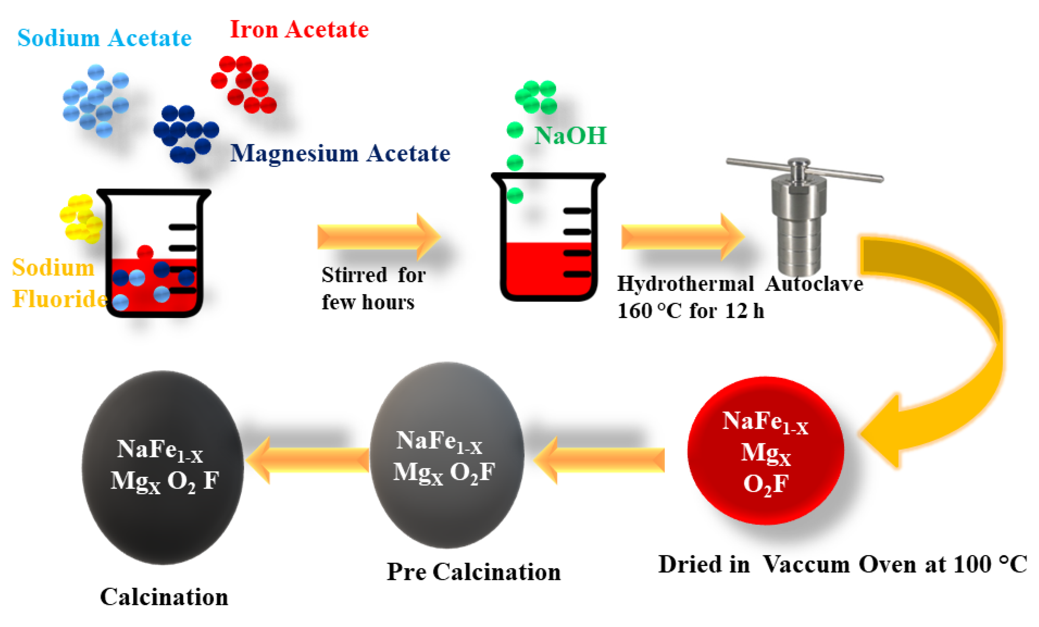
Figure 1. The Schematic Preparation of O3-NaFe1-xMgxO 2F through the hydrothermal method.
Inorganics 11 00037 g001
Figure 2. (a) XRD and refinement results of (b) NMFF1, (c) NMFF2, (d) NMFF3, and (f) NMFF4 (e) crystal structure of O3-type NaFe1-xMgxO2.
Inorganics 11 00037 g002
Figure 3. (ad) FESEM images of NMFF1, NMFF2, NMFF3, and NMFF4. (e) EDS spectrum of the prepared samples.
Inorganics 11 00037 g003
Figure 4. (ad) HRTEM images of NMFF1, NMFF2, NMFF3, and NMFF4, (ei) HRTEM fringes image of NMFF1–NMFF4.
Inorganics 11 00037 g004
Figure 5. (ad) XPS patterns of NMFF1, NMFF2, NMFF3, and NMFF4. (e) Na1s spectra and (f) deconvoluted spectrum of oxygen.
Inorganics 11 00037 g005
Figure 6. (ad) Bet surface area analysis of NMFF1-NMFF4, inserted with pore size distribution.
Inorganics 11 00037 g006
Figure 7. (ad) CV analysis of NMFF1, NMFF2, NMFF3, and NMFF4; (eh) Charge discharge pattern of NMFF1, NMFF2, NMFF3, and NMFF4 at 50 mA g−1.
Inorganics 11 00037 g007
Figure 8. (a) Cyclic performance of NMFF1, NMFF2, NMFF3, and NMFF4; and (b) rate performance of NMFF1, NMFF2, NMFF3, and NMFF4.
Inorganics 11 00037 g008
Figure 9. Schematic showing of electrodes’ arrangements in a coin cell.
Inorganics 11 00037 g009
Figure 10. The FESEM images of the samples, taken after 500 cycles.
Inorganics 11 00037 g010
Figure 11. (a) EIS analysis before cycling (b) EIS analysis after cycling (c) equivalent circuit.
Inorganics 11 00037 g011
Table 1. ICP analysis of the prepared samples.
NaFeMgFO
Calculated Ratio
NMFF10.4000.9000.1000.1500.200
NMFF20.4000.8000.2000.1500.200
NMFF30.4000.6000.4000.1500.200
NMFF40.4000.5000.5000.1500.200
Ratios by ICP analysis
NMFF10.4010.8990.1010.1500.200
NMFF20.4010.7880.2120.1500.200
NMFF30.4010.6000.4000.1500.200
NMFF40.4010.5000.5000.1500.200
Table 2. Resistance value calculated from EIS analysis.
Before CyclingR1/kΩR2/
NMFF110.1116.06
NMFF28.6614.21
NMFF37.2313.12
NMFF46.5211.47
After
Cycling
R1/kΩR2/kΩ
NMFF111.2582.32
NMFF210.7880.54
NMFF38.5675.56
NMFF47.9871.23
Table 3. Comparison with the previous work.
SampleCapacity (mAh g−1)Current (mA/g)Voltage/V vs. NaReference
O3–NaFeO298 502.0–4.0 [8]
NaFeO280 500–4 [10]
O3-NaFeO285 202.0–4.0 [19]
NaFeO2121 1002.0–4.0 [20]
NaFe1-xMgxO2158 502.0–4.0 [25]
NaFe1-xMgxO2F163502.0–4.5Present work
Disclaimer/Publisher’s Note: The statements, opinions and data contained in all publications are solely those of the individual author(s) and contributor(s) and not of MDPI and/or the editor(s). MDPI and/or the editor(s) disclaim responsibility for any injury to people or property resulting from any ideas, methods, instructions or products referred to in the content.