Article

Effect of Salt Variability on the Low-Temperature Metal-Catalyzed Graphitization of PAN/DMSO Solutions for the Synthesis of Nanostructured Graphitic Carbon

1
Department of Nano Convergence Engineering, Jeonbuk National University, Jeonju-561756, Republic of Korea
2
Department of Organic Materials and Textile Engineering, Jeonbuk National University, Jeonju-561756, Republic of Korea
*
Authors to whom correspondence should be addressed.
Inorganics 2024, 12(8), 212; https://doi.org/10.3390/inorganics12080212 (registering DOI)
Submission received: 12 June 2024 / Revised: 29 July 2024 / Accepted: 31 July 2024 / Published: 2 August 2024
(This article belongs to the Section Inorganic Solid-State Chemistry)

Abstract

:
Graphitic carbon plays a pivotal role in numerous technological applications, including energy storage, energy conversion, and different fields of material science. The transformation of amorphous carbon into graphitic carbon, a process known as graphitization, is important for optimizing the properties of carbon materials. In this study, we explore the catalytic graphitization of polyacrylonitrile (PANs) using various metal salts (LiNO3, Ca(NO3)2·4H2O, and Ni(NO3)2·6H2O). We prepared dimethyl sulfoxide (DMSO) solutions of PAN with different salt concentrations of 5, 10, and 15 wt.%. The different prepared metal salt-mixed PAN/DMSO solutions were dried at 45 °C and this was followed by carbonization processes at 950 °C, with a heating rate of 1 °C min−1 for 1 h under an N2 atmosphere. The resulting graphitic carbon was characterized to determine the influence of salt type and concentration on the degree of graphitization. Our findings provide valuable insights into PAN-derived graphitic carbon’s structural and compositional properties. This work underscores the influence of salt concentration in optimizing the graphitization process, offering a pathway to design facile and cost-effective graphitic carbon materials.

1. Introduction

Carbon has been crucial in technological development throughout history. Today, carbon, especially graphitic carbon, is essential in energy applications such as batteries, fuel cells, supercapacitors, environmental applications, pigments, and separation/purification science [1,2,3]. The process of graphitization, which involves the transformation of amorphous carbon to graphitic carbon, underscores its importance [4]. A promising method for the synthesis of graphitized carbon is graphitization via high-temperature carbonization. This process involves the thermal transformation of amorphous carbon into graphitic carbon by heat treatment at higher temperatures [5,6]. Polymers such as polyacrylonitrile (PAN) have been extensively studied because of their ability to graphitize easily, adjustable structure, and their potential to incorporate metal-containing additives [7,8,9]. PAN can be processed into a wet gel with a metal salt solution or by impregnating an insoluble carbon precursor with a metal solution [10]. The controlled graphitization of the PAN precursor into a graphitic carbon is challenging; however; it offers versatile applications. Various transition metals and alkaline earth metals have been extensively used for the promotion of catalytic graphitization.
Catalytic graphitization of a polyacrylonitrile (PAN)-based carbon is a useful technique for producing a graphitic nanostructure within solid carbon materials by utilizing different metal salts such as LiNO3, Ca(NO3)2·4H2O, and Ni(NO3)2·6H2O [11,12,13]. This method enables the preparation of partially graphitized carbon upon carbonization at 950 °C, offering low-cost and straightforward processing [14,15,16]. The graphitic PAN-based carbon with a disordered pore structure can be obtained by combining the PAN solution with different salt solutions followed by stabilization and graphitization [17,18]. Hence, unraveling the effect of salt concentrations in the degree of graphitization of PAN is required to optimize the level of graphitized carbon for versatile applications. Graphitic carbon, produced through enhanced graphitization catalyzed by Li, Ca, and Ni, shows significant potential in advancing various technologies. In energy storage, it could revolutionize batteries and supercapacitors by offering higher energy densities and improved cyclic stability, crucial for electric vehicles and grid-scale storage [19]. In catalysis, graphitic carbon’s high surface area and unique electronic properties can boost catalytic efficiency, promoting more sustainable industrial processes [20,21]. Additionally, its potential for the adsorption and removal of pollutants from air and water supports cleaner environments [22]. These benefits highlight the transformative potential of enhanced graphitic carbon in high-tech applications, from energy to environmental remediation.
Herein, we prepared a polyacrylonitrile solution (PANs) containing different wt. % (5%, 10%, and 15%) of various salts LiNO3, Ca(NO3)2·4H2O, and Ni(NO3)2·6H2O in DMSO. In the preparation of the PAN solution, we used DMSO as a solvent instead of DMF due to the advantages that DMSO is less toxic, has high thermal stability, and has good solubility, resulting in a clear homogenous solution [23]. The as-prepared solutions were dried at a low temperature (45 °C) followed by carbonization in a tube furnace at nitrogen temperature. The effect of the different concentrations of various salts on the graphitization of the PAN/DMSO solution was extensively characterized. This work offers valuable insights into the influence of different salt concentrations on the graphitization process of synthesized PAN/DMSO solutions, elucidating the key factors affecting the structural and compositional properties of the resulting graphitic carbon.

2. Results and Discussion

The various metal salt-influenced PAN-based graphitized carbon samples were fabricated through a low-temperature solidification process followed by subsequent carbonization, as illustrated in Figure 1. Figure S1 demonstrates the photographic images of a solution mixture of different metal catalysts at various wt% and PAN-based polymer solutions. The structural morphology of the as-prepared samples was examined using FE-SEM. Figure S2 shows the FE-SEM images of solid-state PAN without a metal catalyst, highlighting a decrease in surface roughness and showing that there are no significant changes in the physical structure of the pure PANs after the carbonization process. Figure S3 shows the FE-SEM images of the solidified mixtures of lithium metal catalyst and PAN-based materials (Li-PANs-5, Li-PANs-10, and Li-PANs-15), revealing changes in surface structure and roughness after incorporating the metal catalyst into the PAN matrix.
The FE-SEM images of the solidified mixture of lithium salt and PAN-based materials after carbonization (Li-GC-5, Li-GC-10, and Li-GC-15) are presented in Figure 2, revealing significant morphological changes after carbonization. These alterations result from reactions between the lithium metal catalyst and PAN-based carbon during the carbonization process, leading to the development of voids and a porous structure. As shown in Figure 2a–c, the variation in surface structures and void shapes observed in the morphological analysis may be attributed to the different weight percentages of the Li metal catalyst used in the synthesis process. Furthermore, the elemental mapping analysis presented in Figure 2c,f,i provides detailed insights into the composition of the synthesized materials. This analysis confirms that the Li salts are effectively removed during the carbonization process, resulting in the formation of pure carbon materials derived from the PAN-based polymer. The absence of residual Li salts in the final product suggests that the carbonization process was efficient, leaving behind a clean and graphitized carbon matrix.
Similarly, Figure S4 presents the FE-SEM images of solidified mixtures of calcium catalyst and PAN-based materials (Ca-PANs-5, Ca-PANs-10, and Ca-PANs-15). After adding the calcium metal catalyst, small bead-like particles increase with the metal catalyst’s weight percentage in the PAN polymer solution, indicating a homogeneous mixture of the metal catalyst and PAN solution. As shown in Figure 3a,b,d,e, Ca-GC-5 and Ca-GC-10 exhibit significant morphological changes after carbonization, which can be attributed to the graphitization process. Similarly, the FE-SEM images of Ca-GC-15 (Figure 3g,h) reveal a more distinctive and significantly irregular morphology compared to Ca-GC-5 and Ca-GC-10. This observation suggests that the weight percentage of the calcium metal catalyst plays a substantial role during the carbonization process, leading to more pronounced morphological changes and increased aggregation within the PAN carbon matrix. These aggregated structures imply that the weight percentage of the metal catalyst also affects the overall uniformity and distribution of graphitic nanostructures on the surface. The EDS elemental mapping of Ca-GC-5 (Figure 4c,c1–c5), Ca-GC-10 (Figure 4f,f1–f5), and Ca-GC-15 (Figure 4i,i1–i5) reveals the consistent distribution of calcium within the carbon matrix following the graphitization process.
Additionally, the FE-SEM images of the mixture of nickel metal catalyst and PAN-based materials (Ni-PANs-5, Ni-PANs-10, and Ni-PANs-15) are shown in Figure S5. These images display the aggregated structure that forms after the addition of the Ni metal catalyst to the PAN-based material. The FE-SEM images of Ni-GC-5, Ni-GC-10, and Ni-GC-15 after carbonization depict the formation of spherical nanostructures, attributed to the nickel catalyst melting and dissolving into the amorphous carbon matrix via the dissolution–precipitation mechanism [24]. This highlights the significant influence of the nickel metal catalyst on the graphitization process of PAN-based materials. Moreover, an increase in the wt% of Ni catalyst leads to denser and larger spherical structures, potentially impacting the degree of graphitization in polymer-based carbon materials. The elemental mapping of Ni-GC-5 (c, c1, c2, c3, c4, and c5), Ni-GC-10 (f, f1, f2, f3, f4, and f5), and Ni-GC-15 (i, i1, i2, i3, i4, and i5) reveals the uniform distribution of Ni metal into the carbon matrix during the carbonization process, suggesting a positive effect on the graphitization of PAN-based carbon materials.
X-ray diffraction (XRD) was employed to analyze the change in bulk crystallinity structure based on the ratio of Li, Ca, and Ni metal catalysts. The XRD patterns of the solidified PANs containing various metal catalysts (Li-PANs-5, Li-PANs-10, and Li-PANs-15), (Ca-PANs-5, Ca-PAN-10, and Ca-PANs-15), and (Ni-PANs-5, Ni-PANs-10, and Ni-PANs-15), as well as pure PANs, are displayed in Figure S6 for comparative analysis of the distribution of different metal catalysts within the PANs polymer matrix.
Similarly, XRD patterns after graphitization are demonstrated in Figure 5. Puer PANs after carbonization (Figure 5a) show a broad peak derived from the entangled turbostatic carbon structure of PANs, whereas all M-PNAs-x (M = Li, Ca, and Ni metal catalysts, x = wt%) exhibit the development of the peak at 26°, which is attributable to the (002) plane of graphitic carbon (JCPDS card No. 75-2078). In the case of Li-GC-wt%, Ca-GC-wt%, and Ni-GC-wt% (where, wt% = 5, 10, and 15), additional peaks besides the broad peaks related to graphitized carbon appear, indicating metal–carbon interactions after carbonization. The differences in nature and peak intensities may be influenced by the weight percentage and various mechanisms of the applied metals in catalytic graphitization. So, at a high wt% of metal, the narrow and intense peaks were observed in the XRD pattern (Figure 5b–d). Among the inorganic additives for catalytic graphitization, melted Ni directly dissolves amorphous carbon in forming the graphitic carbon process, while lithium and calcium salts can act as catalysts for certain reactions by which oxidation alters the thermal decomposition pathway and enhances the rate of graphitization during carbonization. Li, Ca, and Ni salts catalyze the graphitization of carbonaceous precursors by reducing the activation energy for carbon atom rearrangement during heat treatment. This promotes graphitic domain formation, as shown by Raman spectroscopy. The salts’ effectiveness depends on their solubility, reactivity with carbon, and thermal stability [25,26].
Furthermore, Raman spectroscopy is a crucial tool for characterizing carbon-based materials, often called the fingerprint for their detailed bonding structure. The Raman spectrum of carbon-based materials primarily exhibits three fundamental bands: the D-band, G-band, and 2D-band [27,28]. The D-band, or Disorder Band, arises from the breathing modes of sp2 atoms in rings and is activated by defects in the sp2 carbon lattice, such as edge plane vibrations, vacancies, and grain boundaries. A higher intensity of the D-band indicates more defects [29,30]. The G-band, or Graphite Band, corresponds to the E2g phonon at the Brillouin zone center and represents the in-plane vibrations of sp2-bonded carbon atoms. This band signifies the crystallinity and quality of graphitic materials [31]. Additionally, the 2D band, or G’ band, reveals the number and stacking order of graphene layers and helps quantify the disorder, crystallinity, and structural properties of carbon nanomaterials [32]. The Raman spectra of carbon material from PAN-based polymers after graphitization using metal catalysts reveal three fundamental bands: a D band (1320–1365 cm−1), G band (1560–1590 cm−1), and 2D band (~2730 cm−1), as shown in Figure 5. The broadening of the G band is owing to the disorders or defects in the prepared graphite using metal catalysts in the carbonization process. As shown in Figure 5a–c, all carbonized materials (Li-GC-5, 10, and 15), (Ca-GC-5, 10, and 15), and (Ni-GC-5, 10, and 15) exhibit distinctive broad peaks at approximately 2730 cm−1, indicating a higher degree of carbon ordering resembling graphene layers. As shown in Table 1, the ID/IG ratios for graphitization using the 5, 10, and 15 wt% of Li, Ca, and Ni catalysts are lower compared to the ID/IG ratio of pristine GC (1.026). This lower ratio validates the decreased sp2 carbon domains after graphitization with these metal catalysts. Similarly, among the various wt% of calcium metal catalysts, 5 wt% has the lowest ID/IG ratio (0.994) compared to 10 and 15 wt% Ca metal catalysts. At high concentrations of Ca salt, more calcium oxide or other calcium compounds may form during the carbonization process. These impurities can introduce defects and disrupt the formation of graphitic structures, leading to a decrease in the degree of graphitization. Furthermore, a large amount of calcium salt can alter the thermal decomposition pathway of the PAN polymer, affecting the carbonization process. The altered pathway can lead to incomplete conversion to graphite, resulting in a higher ID/IG ratio. Thus, the optimal concentration of 5 wt% of metal catalyst effectively facilitates the graphitization process, resulting in a more ordered carbon structure. However, with the nickel (Ni) metal catalyst, there is a decrease in the ID/IG ratio as the weight percentage of the metal catalyst increases. At 15 wt% of Ni catalyst (Ni-GC-15), a notable ID/IG ratio of 0.97 is observed, which is lower than the values for 5 and 10 wt% of Ni catalyst. Among the inorganic additives, melted Ni directly dissolves amorphous carbon to form graphitic carbon during catalytic graphitization [24]. Therefore, at a high wt% of Ni catalyst, more amorphous carbon is dissolved by the melted Ni catalyst during carbonization and then precipitated, resulting in a higher yield of graphitized carbon. In contrast, lithium and calcium salts act as catalysts, forming oxides that alter the thermal decomposition pathway and enhance graphitization. Additionally, Figure 6d–f are the images of the sample location, from where RAMAN analysis was done. In summary, based on the analysis of the ID/IG ratio of different samples, the impact of Li, Ca, and Ni salts on the degree of graphitization is as follows: Ca(NO3)2·4H2O < LiNO3 < Ni(NO3)2·6H2O. Additionally, the degree of graphitization increases with the concentration of the nickel salt: 5 wt% < 10 wt% < 15 wt%. Hence, an optimal amount of nickel metal is considered a suitable catalyst among lithium and calcium metal catalysts to achieve highly graphitized carbon. The ID/IG ratio of the synthesized materials is compared to that of similar materials published earlier (Table S1).
The elemental composition and chemical states present on the surfaces of pristine GC, Ca-GC-5, Li-GC-10, and Ni-GC-15 samples are summarized in the low-resolution X-ray Photoelectron Spectroscopy (XPS) spectra, as presented in Figure 7. All the figures of deconvoluted XPS survey spectra are presented in Figure S7. The precise binding energies and chemical environments of C1s, N1s, O1s, and Ni2p are revealed by the deconvoluted XPS survey spectra for Ni-GC-15 (as in Figure S7a1–a4), demonstrating the presence of nickel and its interaction with the carbon matrix. While the N1s spectrum exhibits peaks representing distinct nitrogen functions, the C1s spectrum reveals peaks corresponding to diverse carbon states, such as C-C, C-O, and C=O [33,34]. The presence of nickel is confirmed by the Ni2p spectrum, which shows distinct peaks for Ni2p3/2 and Ni2p1/2 [35,36]. The O1s spectrum emphasizes that the incorporation of oxygen species Lithium is also visible in the deconvoluted spectra for Li-GC-10 (as in Figure S7b1–b4), which include C1s, N1s, O1s, and Li1s. The deconvoluted spectra of C1s, N1s, O1s, and Ca2p for Ca-GC-5 (as in Figure S7c1–c4) show the presence of incorporated calcium and the different peaks in the Ca2p spectrum correspond to the different chemical states of calcium. When comparing the natural chemical states of carbon, nitrogen, and oxygen in graphitic carbon (GC) without any metal inclusion, the pristine GC’s C1s, N1s, and O1s spectra give a baseline. The deconvoluted spectra exhibit distinct binding energies and relative intensities of the peaks, providing valuable information about the chemical changes and interactions resulting from the addition of various metals (Ni, Li, and Ca) to the GC matrix. These modifications impact the graphitization of the carbon with electronic structure and possibly the electrocatalytic characteristics of the resulting materials.
The high-resolution TEM (HR-TEM) and Transmission Electron Microscopy (TEM) examinations of four samples, Ni-GC-15, Li-GC-10, Ca-GC-5, and pristine GC, are shown in Figure 8. Figure 8a,b of Ni-GC-15 shows well-dispersed nickel nanoparticles embedded in the carbon matrix and HR-TEM verifies the nickel particles’ crystalline structure with a graphitic layer. Li-GC-10 is shown in Figure 8c,d, showing equally dispersed lithium in the carbon matrix. HR-TEM emphasizes how amorphous the lithium incorporation is. Figure 8e,f, for Ca-GC-5, demonstrates the existence of calcium particles and the deep insights into the lattice fringes of the calcium crystals shown by HR-TEM indicate crystallinity with graphitic carbon. Lastly, the pure GC Figure 8g,h highlights the well-ordered amorphous carbon with HR-TEM. This indicates that after metal-catalyzed low-temperature graphitization of the pristine GC, the distinctive graphitic layers and structures are in the presence of metals. Comparing the carbon films’ microstructure and crystallinity to the pristine GC, these studies show how the various metal incorporations (Ni, Li, and Ca) impact graphitic properties.
Additionally, we perform atomic force microscopy (AFM). The surface morphology and roughness of the produced samples are thoroughly analyzed using the AFM findings. For every sample, both top and slanted view photos are shown in Figure S8. The pristine GC is seen in images (a) and (b), which have a comparatively smooth surface with little roughness, indicative of well-prepared graphitic carbon. Ca-GC-5 is seen in images (c) and (d), where the surface is much rougher than in the pure GC. This indicates the incorporation of calcium, which disturbs the smoothness of the graphitic layers. Li-GC-10 is similarly depicted in figures (e) and (f), where the surface roughness has grown even more, indicating considerable surface alterations brought on by the addition of lithium. Lastly, because of the implanted nickel nanoparticles, photos (g) and (h) of Ni-GC-15 show the highest surface roughness of all the samples. These images also have the most apparent surface characteristics and textures. These AFM pictures demonstrate how adding various metals to the graphitic carbon matrix dramatically changes the surface morphology, making it rougher and affecting the material’s characteristics and performance in uses like energy storage or catalysis.

3. Materials and Methods

3.1. Chemical and Materials

The required materials are explained in the Supporting Information file (ESI), Section S1.1.

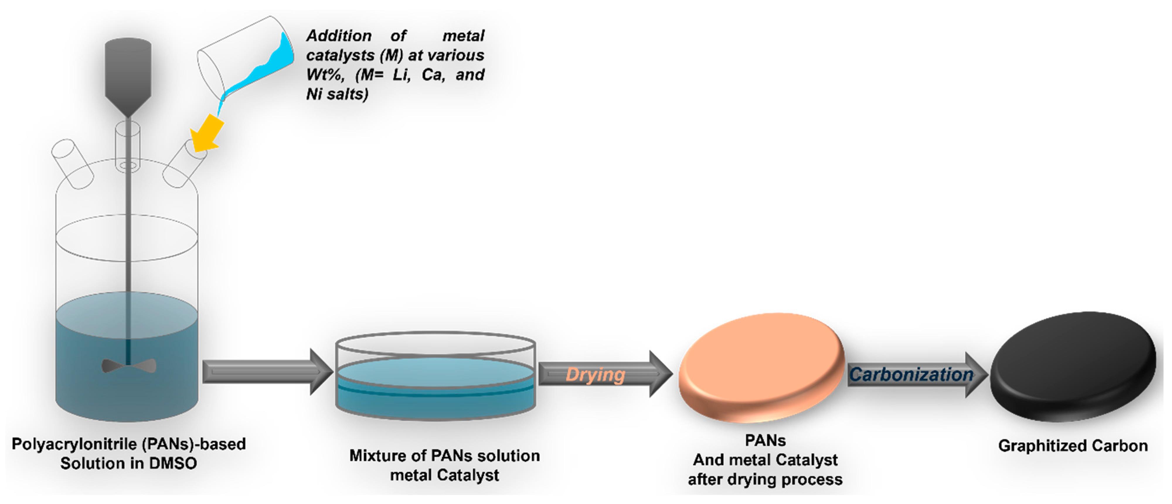
3.2. Preparation of the Nanostructured Graphitic Carbons at Low Temperature

In this work, a PAN-based polymer solution was prepared by dissolving acrylonitrile, itaconic acid, 1-dodecanethiol, and 2,2-azobisisobutyronitrile in 100 mL of DMSO. To this solution, 5%, 10%, and 15% of nitrate metal salts such as lithium, calcium, and nickel were added and vigorously mixed to make a homogeneous mixture. The resulting solution was designated as Li-PANs-5, Li-PANs-10, and Li-PANs-15 for lithium, Ca-PANs-5, Ca-PANs-10, and Ca-PANs-15 for calcium, and Ni-PANs-5, Ni-PANs-10, and Ni-PANs-15 for nickel, based on the respective metal salts used. The mixture was then dried using a low-temperature (45 °C) heating process for 12 h. The dried product was then carbonized in a tubular furnace at 950 °C, with a heating rate of 1 °C min−1 for 1 h under an N2 atmosphere. The resulting materials were designated as Li-GC-5, Li-GC-10, and Li-GC-15 for lithium; Ca-GC-5, Ca-GC-10, and Ca-GC-15 for calcium; and Ni-GC-5, Ni-GC-10, and Ni-GC-15 for nickel, based on the respective metal salts used.

3.3. Material Characterizations

The as-prepared materials’ structural features, morphology, and elemental compositions were studied with field emission scanning electron microscopy (FE-SEM, Carl Zeiss, Oberkochen, Germany) with an instrument equipped with energy-dispersive X-ray spectroscopy (EDXS). The phase, as well as the structure of all the samples, was studied with X-ray diffraction (XRD, Rigaku Corporation, Tokyo, Japan, CuKα radiation, wavelength λ = 0.154 nm) in the 2 θ range from 5–80° at a scan rate of 2° min−1. The graphitization of all prepared samples was analyzed by Raman spectroscopy at room temperature using a Raman spectrometer (RAMANtouch, Seoul, South Korea) from Nanophoton, with an argon ion laser source at an excitation wavelength of 523 nm, conducted at the Gunsan National University Center for Research Facilities. The surface chemistry and the binding energy of different electronic states of the samples were examined by XPS with a K-alpha X-ray photoelectron spectrometer (Thermo Scientific, Waltham, MA, USA, Nexsa XPS system) at KBSI, Jeonju center. The surface roughness of the as-prepared samples was measured by atomic force microscopy (AFM, Bruker, Multimode-8, Billerica, MA, USA) under ambient laboratory conditions. FE-SEM, EDX, AFM, and XRD analyses were performed at the Center for University-wide Research Foundation (CURF), Jeonbuk National University.

4. Conclusions

This paper investigates the catalytic effect of metal catalysts (Li, Ca, and Ni) on the graphitization of PAN-based polymer materials. The results demonstrate that adding metal catalysts to PAN-based polymer significantly enhances the degree of graphitization. Low-temperature metal catalytic graphitization proves to be more efficient than other conventional graphitization techniques. Nickel metal catalyst notably improves the degree of graphitization compared to other catalysts (Li and Ca), as indicated by Raman analysis and the calculated ID/IG ratio after carbonization. However, a high concentration of Li and Ca restrains graphite crystalline growth as the aggregation of metal carbide particles from thermal treatment adversely affects structural order. The catalytic effect of metal catalysts, particularly nickel, on the graphitization of PAN-based polymers opens new avenues for improving the properties and performance of carbon-based materials in various high-tech applications, such as electrochemical energy storage and conversion. Future research could explore optimizing catalyst concentrations and combinations to further enhance graphitization efficiency and material properties.

Supplementary Materials

The following supporting information can be downloaded at https://www.mdpi.com/article/10.3390/inorganics12080212/s1: Figure S1: Photographic image PANs solution with different metal salt (catalyst) at various wt%; Figure S2: Fe-SEM image: (a and b) PANs after the drying process, (c and d) graphitized carbon (GC) of pure PANs after carbonization, and (e, e1, e2, and e3) its elemental mapping; Figure S3: Morphological characterizations: (a and b) FE-SEM images and (c, c1, c2, c3, c4, and c5) elemental mapping of Li-PANs-5, (d and e) FE-SEM images and (f, f1, f2, f3, f4, and f5) elemental mapping of Li-PANs-10, (g and h) FE-SEM images and (i, i1, i2, i3, i4, and i5) elemental mapping of Li-PANs-15 after drying process; Figure S4: Morphological characterizations: (a and b) FE-SEM images and (c, c1, c2, c3, c4, and c5) elemental mapping of Ca-PANs-5, (d and e) FE-SEM images and (f, f1, f2, f3, f4, and f5) elemental mapping of Ca-PANs-10, (g and h) FE-SEM images and (i, i1, i2, i3, i4, and i5) elemental mapping of Ca-PANs-15 after drying process; Figure S5: Morphological characterizations: (a and b) FE-SEM images and (c, c1, c2, c3, c4, and c5) elemental mapping of Ni-PANs-5, (d and e) FE-SEM images and (f, f1, f2, f3, f4, and f5) elemental mapping of Ni-PANs-10, (g and h) FE-SEM images and (i, i1, i2, i3, i4, and i5) elemental mapping of Ni-PANs-15 after drying process; Figure S6: XRD analysis: (a) XRD pattern of Li-PANs-5, Li-PANs-10, and Li-PANs-15 (b) XRD pattern of Ca-PANs-5, Ca-PANs-10, and Ca-PANs-15, and (c) XRD pattern of Ni-PANs-5, Ni-PANs-10, and Ni-PANs-15 after drying process; Figure S7: Deconvoluted XPS survey spectra of (a1, a2, a3, and a4) C1s, N1s, O1s, and Ni2p, respectively, of Ni-GC-15, (b1, b2, b3, and b4) C1s, N1s, O1s, and Li1s, respectively, of Li-GC-10, (c1, c2, c3, and c4) C1s, N1s, O1s, and Ca2p, respectively, of Ca-GC-5, (d1, d2, and d3) C1s, N1s, and O1s, respectively, of pristine GC; Figure S8: Top and tilted view AFM images of (a and b) pristine GC, (c and d) Ca-GC-5, (e and f) Li-GC-10, and (g and h) Ni-GC-15; and Table S1: ID/IG ratio of earlier published similar materials.

Author Contributions

Conceptualization, T.K. and H.Y.K.; Data curation, B.-S.K. and H.Y.K.; Formal analysis, B.-S.K., T.H.K. and H.Y.K.; Funding acquisition, T.H.K.; Investigation, B.-S.K., T.H.K. and H.Y.K.; Methodology, T.K. and H.Y.K.; Project administration, T.H.K.; Resources, H.Y.K.; Software, B.-S.K.; Supervision, T.H.K. and H.Y.K.; Validation, H.Y.K.; Visualization, T.K.; Writing—original draft, T.K.; Writing—review and editing, T.K. and H.Y.K. All authors have read and agreed to the published version of the manuscript.

Funding

This work was supported by the Korean Research Institute for Defense Technology Planning and Advancement (KRIT) grant funded by the Korean government (DAPA-Defense Acquisition Program Administration) (Grant No. KRIT-CT-22-025, Ultra-High Modulus Carbon Fiber Research Laboratory).

Data Availability Statement

Data is contained within the article or Supplementary Materials.

Conflicts of Interest

The authors declare no conflicts of interest.

References

  1. Hunter, R.D.; Ramírez-Rico, J.; Schnepp, Z. Iron-catalyzed graphitization for the synthesis of nanostructured graphitic carbons. J. Mater. Chem. A 2022, 10, 4489–4516. [Google Scholar] [CrossRef]
  2. Guo, S.; Wang, J.; Chen, F.; Sun, Y.; Liu, Y.; Wang, L.; Li, C. String of ZIF-derived hollow beaded nanocage embedded into carbon nanofiber with intensified exposed Co-Nx sites for efficient oxygen catalysis in various fuel cell devices. Chem. Eng. J. 2023, 463, 142498. [Google Scholar] [CrossRef]
  3. Bhattarai, R.M.; Le, N.; Chhetri, K.; Acharya, D.; Pandiyarajan, S.M.S.; Saud, S.; Kim, S.J.; Mok, Y.S. Synergistic Performance Boosts of Dopamine-Derived Carbon Shell Over Bi-metallic Sulfide: A Promising Advancement for High-Performance Lithium-Ion Battery Anodes. Adv. Sci. 2024, 11, 2308160. [Google Scholar] [CrossRef] [PubMed]
  4. Cipriani, E.; Zanetti, M.; Bracco, P.; Brunella, V.; Luda, M.P.; Costa, L. Crosslinking and carbonization processes in PAN films and nanofibers. Polym. Degrad. Stab. 2016, 123, 178–188. [Google Scholar] [CrossRef]
  5. Kunwar, J.; Acharya, D.; Chhetri, K.; Karki, B.; Deo, B.; Bhattarai, R.M.; Neupane, S.; Adhikari, M.P.; Yadav, A.P. Cobalt oxide decorated 2D MXene: A hybrid nanocomposite electrode for high-performance supercapacitor application. J. Electroanal. Chem. 2023, 950, 117915. [Google Scholar] [CrossRef]
  6. Li, H.; Wu, A.; Qiu, Z.; Li, J.; Wu, Z.; Ma, Y.; Wang, J.; He, S.; Huang, H. Carbonization of Ni@SiC@C nanoparticles reinforced PAN nanofibers for adjustable impedance matching. Chem. Eng. J. 2023, 476, 146582. [Google Scholar] [CrossRef]
  7. Li, L.; Chen, Z.; Pan, F.; Guo, H.; Wang, X.; Cheng, J.; Cai, L.; Xiu, Z.; Chen, L.; Batalu, D.; et al. Electrospinning technology on one dimensional microwave absorbers: Fundamentals, current progress, and perspectives. Chem. Eng. J. 2023, 470, 144236. [Google Scholar] [CrossRef]
  8. Storck, J.L.; Hellert, C.; Brockhagen, B.; Wortmann, M.; Diestelhorst, E.; Frese, N.; Grothe, T.; Ehrmann, A. Metallic Supports Accelerate Carbonization and Improve Morphological Stability of Polyacrylonitrile Nanofibers during Heat Treatment. Materials 2021, 14, 4686. [Google Scholar] [CrossRef]
  9. Zhou, H.; Zhu, J.; Wang, H.-L. Tuning of structural/functional feature of carbon fibers: New insights into the stabilization of polyacrylonitrile. Polymer 2023, 282, 126157. [Google Scholar] [CrossRef]
  10. Chhetri, K.; Kim, T.; Acharya, D.; Muthurasu, A.; Dahal, B.; Bhattarai, R.M.; Lohani, P.C.; Pathak, I.; Ji, S.; Ko, T.H.; et al. Hollow Carbon Nanofibers with Inside-outside Decoration of Bi-metallic MOF Derived Ni-Fe Phosphides as Electrode Materials for Asymmetric Supercapacitors. Chem. Eng. J. 2022, 450, 138363. [Google Scholar] [CrossRef]
  11. Li, G.; Guo, H.; Wang, Z.; Yan, G.; Wang, J.; Li, X. A robust in-situ catalytic graphitization combined with salt-template strategy towards fast lithium-ions storage. J. Alloys Compd. 2022, 908, 164717. [Google Scholar] [CrossRef]
  12. Mennani, M.; Ait Benhamou, A.; Mekkaoui, A.A.; El Bachraoui, F.; El Achaby, M.; Moubarik, A.; Kassab, Z. Probing the evolution in catalytic graphitization of biomass-based materials for enduring energetic applications. J. Mater. Chem. A 2024, 12, 6797–6825. [Google Scholar] [CrossRef]
  13. Wang, C.; Li, Y.; Cao, F.; Zhang, Y.; Xia, X.; Zhang, L. Employing Ni-Embedded Porous Graphitic Carbon Fibers for High-Efficiency Lithium–Sulfur Batteries. ACS Appl. Mater. Interfaces 2022, 14, 10457–10466. [Google Scholar] [CrossRef] [PubMed]
  14. Liu, Y.; Liu, Q.; Gu, J.; Kang, D.; Zhou, F.; Zhang, W.; Wu, Y.; Zhang, D. Highly porous graphitic materials prepared by catalytic graphitization. Carbon 2013, 64, 132–140. [Google Scholar] [CrossRef]
  15. Wang, H.; Wang, H.; Sun, R.; Yao, L.; Zuo, H.; Ruan, F.; Feng, Q.; Wang, J. Preparation of hierarchical micro-meso porous carbon and carbon nanofiber from polyacrylonitrile/polysulfone polymer via one-step carbonization for supercapacitor electrodes. Electrochim. Acta 2023, 441, 141827. [Google Scholar] [CrossRef]
  16. Boll, F.; Crisci, M.; Merola, L.; Lamberti, F.; Smarsly, B.; Gatti, T. Assessing the Effect of Stabilization and Carbonization Temperatures on Electrochemical Performance of Electrospun Carbon Nanofibers from Polyacrylonitrile. Adv. Energy Sustain. Res. 2023, 4, 2300121. [Google Scholar] [CrossRef]
  17. Mao, Q.; Rajabpour, S.; Talkhoncheh, M.K.; Zhu, J.; Kowalik, M.; van Duin, A.C.T. Cost-effective carbon fiber precursor selections of polyacrylonitrile-derived blend polymers: Carbonization chemistry and structural characterizations. Nanoscale 2022, 14, 6357–6372. [Google Scholar] [CrossRef] [PubMed]
  18. Franklin, R.; Xu, W.; Ravichandran, D.; Jambhulkar, S.; Zhu, Y.; Song, K. Reinforcing carbonized polyacrylonitrile fibers with nanoscale graphitic interface-layers. J. Mater. Sci. Technol. 2021, 95, 78–87. [Google Scholar] [CrossRef]
  19. Bhattarai, R.M.; Chhetri, K.; Saud, S.; Teke, S.; Kim, S.J.; Mok, Y.S. Eco-Friendly Synthesis of Cobalt Molybdenum Hydroxide 3d Nanostructures on Carbon Fabric Coupled with Cherry Flower Waste-Derived Activated Carbon for Quasi-Solid-State Flexible Asymmetric Supercapacitors. ACS Appl. Nano Mater. 2022, 5, 160–175. [Google Scholar] [CrossRef]
  20. Pathak, I.; Muthurasu, A.; Acharya, D.; Chhetri, K.; Dahal, B.; Rosyara, Y.R.; Kim, T.; Ko, T.H.; Kim, H.Y. Electronically modulated bimetallic telluride nanodendrites atop 2D nanosheets using a vanadium dopant enabling a bifunctional electrocatalyst for overall water splitting. J. Mater. Chem. A 2024, 12, 17544–17556. [Google Scholar] [CrossRef]
  21. Ajiboye, T.O.; Kuvarega, A.T.; Onwudiwe, D.C. Graphitic carbon nitride-based catalysts and their applications: A review. Nano-Struct. Nano-Objects 2020, 24, 100577. [Google Scholar] [CrossRef]
  22. Kandel, D.R.; Poudel, M.B.; Radoor, S.; Chang, S.; Lee, J. Decoration of dandelion-like manganese-doped iron oxide microflowers on plasma-treated biochar for alleviation of heavy metal pollution in water. Chemosphere 2024, 357, 141757. [Google Scholar] [CrossRef]
  23. Chen, L.; Yang, Z.; Yang, Y.; Yang, X.; Wang, G.; Zhu, L.; Zeng, Z. Effective solar-driven evaporators with urchin-like CuO particles and directional polyvinylidene fluoride scaffolds via directional dimethyl sulfoxide crystallization and non-solvent induced phase separation. Sep. Purif. Technol. 2024, 345, 127446. [Google Scholar] [CrossRef]
  24. An, X.; Shin, D.; Ocon, J.D.; Lee, J.K.; Son, Y.-I.; Lee, J. Electrocatalytic oxygen evolution reaction at a FeNi composite on a carbon nanofiber matrix in alkaline media. Chin. J. Catal. 2014, 35, 891–895. [Google Scholar] [CrossRef]
  25. Han, J.; Zhang, L.; Duan, L.; Liu, L.; Xiao, X.; Xin, X.; Li, X. Uniform Li-deposition induced by Ni-catalyzing graphitization of natural carbon materials in lithium metal batteries. ChemNanoMat 2023, 9, e202300194. [Google Scholar] [CrossRef]
  26. Yan, Z.; Huang, D.; Lai, A.; Chu, Y.; Zheng, F.; Cai, Y.; Pan, Q.; Wang, H.; Huang, Y.; Li, Q. Nickel catalyzed graphitized carbon coated LiFe1-xNixPO4 composites as cathode material for high-performance lithium-ion batteries. Electrochim. Acta 2020, 353, 136565. [Google Scholar] [CrossRef]
  27. Nazarov, E.E.; Tyablikov, O.A.; Nikitina, V.A.; Antipov, E.V.; Fedotov, S.S. Polyacrylonitrile-Derived Carbon Nanocoating for Long-Life High-Power Phosphate Electrodes. Appl. Nano 2023, 4, 25–37. [Google Scholar] [CrossRef]
  28. Zeng, J.; Zhao, G.; Liu, J.; Xiang, Y.; Guo, S. Interaction between thermal stabilization temperature program, oxidation reaction, and mechanical properties of polyacrylonitrile (PAN) based carbon fibers. Diam. Relat. Mater. 2024, 141, 110588. [Google Scholar] [CrossRef]
  29. Made Joni, I.; Vanitha, M.; Camellia, P.; Balasubramanian, N. Augmentation of graphite purity from mineral resources and enhancing % graphitization using microwave irradiation: XRD and Raman studies. Diam. Relat. Mater. 2018, 88, 129–136. [Google Scholar] [CrossRef]
  30. Nguyen, L.; Bhattarai, R.M.; Teke, S.; Chhetri, K.; Acharya, D.; Sasikumar, R.; Mok, Y.S. Unlocking enhanced electrochemical performance through oxygen–nitrogen dual functionalization of iron–nickel–sulfide for efficient energy storage systems. J. Mater. Chem. A 2024, 12, 17369–17381. [Google Scholar] [CrossRef]
  31. Wang, N.; Mao, M.; Mao, G.; Yin, J.; He, R.; Zhou, H.; Li, N.; Liu, Q.; Zhi, K. Investigation on carbide slag catalytic effect of Mongolian bituminous coal steam gasification process. Chemosphere 2021, 264, 128500. [Google Scholar] [CrossRef] [PubMed]
  32. Wang, J.; Tu, J.; Lei, H.; Zhu, H. The effect of graphitization degree of carbonaceous material on the electrochemical performance for aluminum-ion batteries. RSC Adv. 2019, 9, 38990–38997. [Google Scholar] [CrossRef] [PubMed]
  33. Bhattarai, R.M.; Chhetri, K.; Le, N.; Acharya, D.; Saud, S.; Nguyen, M.C.H.P.L.; Kim, S.J.; Mok, Y.S. Oxygen functionalization-assisted anionic exchange toward unique construction of flower-like transition metal chalcogenide embedded carbon fabric for ultra-long life flexible energy storage and conversion. Carbon Energy 2024, 6, e392. [Google Scholar] [CrossRef]
  34. Bhattarai, R.M.; Chhetri, K.; Natarajan, S.; Saud, S.; Kim, S.J.; Mok, Y.S. Activated carbon derived from cherry flower biowaste with a self-doped heteroatom and large specific surface area for supercapacitor and sodium-ion battery applications. Chemosphere 2022, 303, 135290. [Google Scholar] [CrossRef] [PubMed]
  35. Kandel, M.R.; Pan, U.N.; Dhakal, P.P.; Ghising, R.B.; Sidra, S.; Kim, D.H.; Kim, N.H.; Lee, J.H. Manganese-Doped Bimetallic (Co,Ni)2P Integrated CoP in N,S Co−Doped Carbon: Unveiling a Compatible Hybrid Electrocatalyst for Overall Water Splitting. Small 2024, 20, 2307241. [Google Scholar] [CrossRef]
  36. Gautam, K.P.; Acharya, D.; Bhatta, I.; Subedi, V.; Das, M.; Neupane, S.; Kunwar, J.; Chhetri, K.; Yadav, A.P. Nickel Oxide-Incorporated Polyaniline Nanocomposites as an Efficient Electrode Material for Supercapacitor Application. Inorganics 2022, 10, 86. [Google Scholar] [CrossRef]
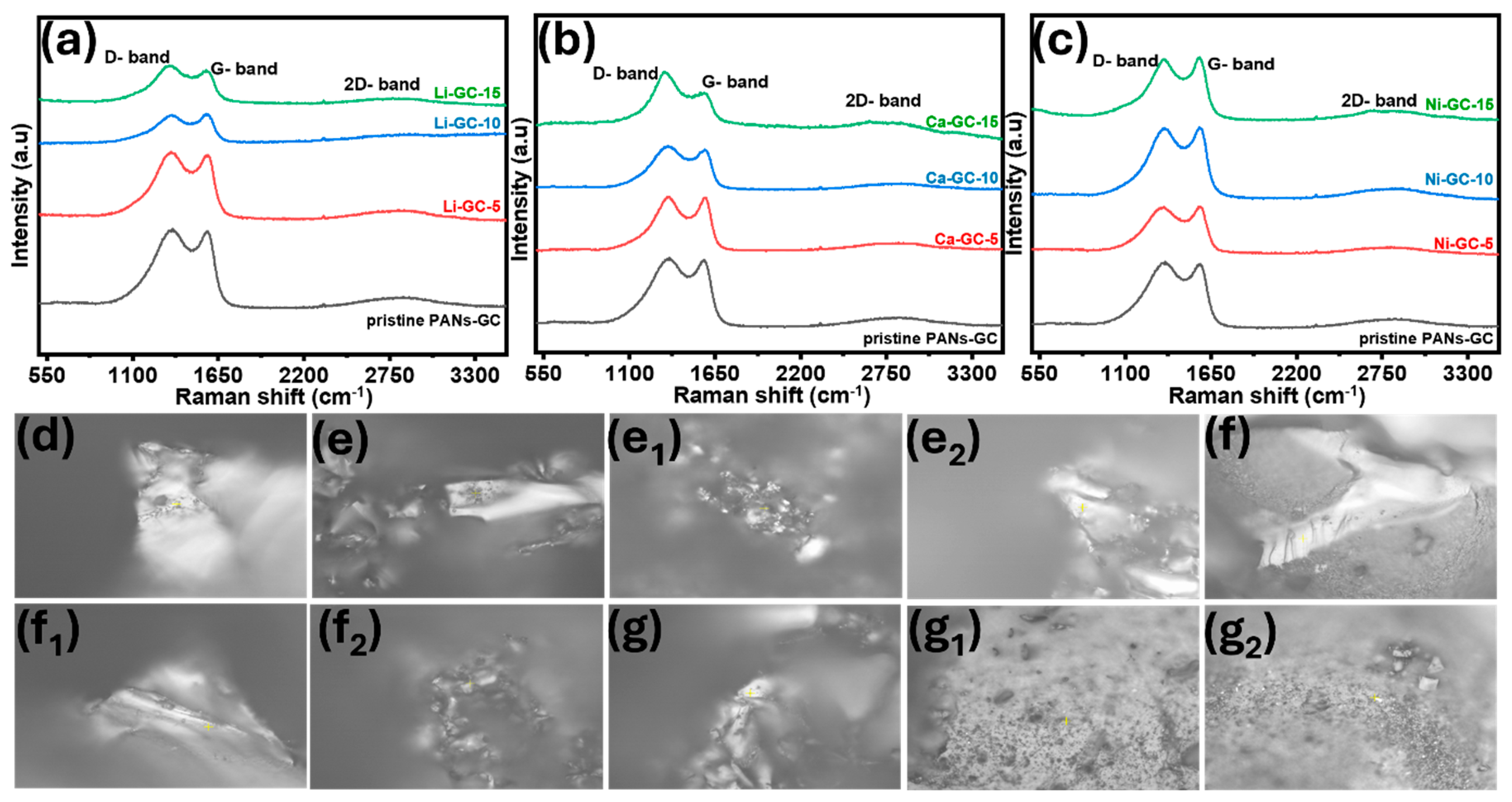
Figure 1. Schematic representation of the synthesis of PAN-based graphitic carbon.
Inorganics 12 00212 g001
Figure 2. Morphological characterizations: (a,b) FE-SEM images; Scale bar: (a) 100 µm, (b) 1 µm, (c) and (c,c1c3) elemental mapping of Li-GC-5; Scale bar: all 50 µm, (d,e) FE-SEM images; Scale bar: (d) 50 µm, (e) 20 µm and (f,f1f3) elemental mapping of Li-GC-10; Scale bar: all 5 µm, (g,h) FE-SEM images; Scale bar: (g) 50 µm, (h) 20 µm, and (i,i1i3) elemental mapping of Li-GC-15 (Scale bar: all 5 µm) after carbonization.
Inorganics 12 00212 g002
Figure 3. Morphological characterizations: (a,b) FE-SEM images; Scale bar: (a) 50 µm, (b) 1 µm, and (c,c1c5) elemental mapping (Scale bar: all 50 µm) of Ca-GC-5, (d,e) FE-SEM images; Scale bar: (d) 2 µm, (b) 10 µm and (f,f1f5) elemental mapping (Scale bar: all 50 µm) of Ca-GC-10, and (g,h) FE-SEM images; Scale bar: (g) 50 µm, (h) 20 µm, and (i,i1i5) elemental mapping (Scale bar: all 20 µm) of Ca-GC-15 after carbonization.
Inorganics 12 00212 g003
Figure 4. Morphological study: (a,b) FE-SEM images; Scale bar: (a) 1 µm, (b) 300 nm, and (c,c1c5) elemental mapping (Scale bar: all 20 µm) of Ni-GC-5; (d,e) FE-SEM images; Scale bar: (a) 50 µm, (b) 1 µm, and (f,f1f5) elemental mapping (Scale bar: all 20 µm) of Ni-GC-10; and (g,h) FE-SEM images; Scale bar: (a) 50 µm, (b) 1 µm, and (i,i1i5) elemental mapping (Scale bar: all 20 µm) of Ni-GC-15 after carbonization.
Inorganics 12 00212 g004
Figure 5. XRD analysis of (a) pristine PANs-GC, (b) Li-GC-5, Li-GC-10, and Li-GC-15, (c) Ca-GC-5, Ca-GC-10, and Ca-GC-15, and (d) Ni-GC-5, Ni-GC-10, and Ni-GC-15 after carbonization.
Inorganics 12 00212 g005
Figure 6. Raman spectra of (a) pristine GC, Li-GC-5, Li-GC-10, and Li-GC-15, (b) pristine GC, Ca-GC-5, Ca-GC-10, and Ca-GC-15, and (c) pristine GC, Ni-GC-5, Ni-GC-10, and Ni-GC-15. Raman images of (d) pristine GC; (e,e1,e2) Li-GC-5, Li-GC-10, and Li-GC-15; (f,f1,f2) Ca-GC-5, Ca-GC-10, and Ca-GC-15; and (g,g1,g2) Ni-GC-5, Ni-GC-10, and Ni-GC-15.
Inorganics 12 00212 g006
Figure 7. Low-resolution XPS spectra of the pristine GC, Ca-GC-5, Li-GC-10, and Ni-GC-15.
Inorganics 12 00212 g007
Figure 8. TEM analysis of (a,b) TEM and HR-TEM images of Ni-GC-15, (c,d) TEM and HR-TEM images of Li-GC-10, (e,f) TEM and HR-TEM images of Ca-GC-5, and (g,h) TEM and HR-TEM images of pristine GC.
Inorganics 12 00212 g008
Table 1. Raman spectroscopy analysis of carbonized PAN-based materials with different metal catalysts.
SamplesPeak Position (D-Band)Peak Position (G-Band)ID/IG Ratio
Pristine GC1361.83 cm−11570.84 cm−11.026
Li-GC-51348.01 cm−11575.33 cm−11.016
Li-GC-101352.62 cm−11565.35 cm−10.994
Li-GC-151343.4 cm−11570.84 cm−11.017
Ca-GC-51352.62 cm−11584.29 cm−11.007
Ca-GC-101348.01 cm−11588.77 cm−11.017
Ca-GC151324.94 cm−11588.77 cm−11.079
Ni-GC-51348.01 cm−11575.33cm−11.003
Ni-GC-101352.62 cm−11566.35 cm−10.994
Ni-GC-151352.62 cm−11570.84 cm−10.979
Disclaimer/Publisher’s Note: The statements, opinions and data contained in all publications are solely those of the individual author(s) and contributor(s) and not of MDPI and/or the editor(s). MDPI and/or the editor(s) disclaim responsibility for any injury to people or property resulting from any ideas, methods, instructions or products referred to in the content.

