Abstract
Lithium–sulfur batteries (LSBs) hold promise for use in next-generation high-energy-density energy storage systems. However, the commercial application of LSBs is hindered by the shuttle effect of polysulfides. In this study, we synthesized a covalent organic framework material (PY−DHBD−COF) and employed it to modify the separators of LSBs in order to buffer the shuttle effect of polysulfides. A modified separator, involving PY−DHBD−COF coating of the commercial Celgard 2500 PP separator, is prepared via a vacuum-assisted self-assembly method. The PY−DHBD−COF features hydroxyl and imine bonds, which can adsorb lithium polysulfides (LiPSs) and buffer the shuttle effect. The PY−DHBD−COF coating exhibits a thin thickness and oriented nanochannels, facilitating electrolyte wetting and Li+ transport. As a result, the LSBs with PY−DHBD−COF-modified separators exhibit a high specific capacity of 373 mAh g−1 at 4 C with only 0.005% capacity decay per cycle after 450 cycles at 2 C, demonstrating an excellent cycling performance.
1. Introduction
Due to their high theoretical energy density (~2600 Wh kg−1) and low cost, lithium–sulfur batteries (LSBs) are considered to be among the most promising energy storage systems [1,2,3]. The separator is a critical component of batteries, influencing the performance of LSBs [4,5]. Traditional LSB separators are made of polyolefin (PP) materials with pores >100 nm. Lithium polysulfides (LiPSs) can pass through the pores of PP separators (shuttle effect), leading to the irreversible loss of active material, self-discharge, and capacity decay. Moreover, lithium polysulfides from the cathode may coat the anode surface and further reduce to short-chain Li2S2/Li2S, promoting Li dendrite growth [6,7,8,9,10]. These issues inhibit the design of high-performance LSBs with good cycling stability and long lifespans. To address these issues, the functional design of separators has been extensively studied. Physically, a physical barrier is designed based on the radius difference between Li+ and Sx2− to optimize the pore size of the separator, while the SLP near the cathode is blocked by electrostatic repulsion [11,12]. Chemically, we incorporate modified-layer materials such as carbon-based materials [13,14], metals, metal compounds [15,16], and organic compounds [17,18] into the separator surface. However, metal catalysts always cause electrolyte decomposition, while organic media inevitably produce side reactions affecting metallic lithium, resulting in poor long-term cycling stability.
Covalent organic frameworks (COFs) are a class of crystalline porous polymers. Constructed via covalent bonding, they have shown advantages when applied in catalysis and electrochemical energy storage devices in recent years [19,20,21]. Covalent bonds endow COFs with excellent chemical stability [22]. COFs hold promise in buffering the LSBs’ shuttle effect due to their tunable chemical properties and high chemical/thermal stability [23,24,25,26,27,28]. Nevertheless, the poor conductivity of COFs limits their applications as hosts for sulfur cathodes. Considering their inherent ordered pores, COFs can be used to modify LSBs’ separator in order to reduce LSBs’ shuttle effect. There are several advantages to using COFs to modify LSBs’ separator: (i) Inherent ordered pores inhibit LiPS shuttle. (ii) The excellent structural controllability promotes Li+ transport [29,30]. In 2019, Cao et al. [31] designed a two-dimensional COF nanosheet (Li-CON) to modify LSBs’ PP separator, reducing LiPS shuttling and facilitating Li+ transport. Xu et al. [32] developed a sulfonate-rich COF (SCOF-2) for PP separator modification. The SCOF-2 features high Li+ conductivity and abundant charge sites, thus preventing LiPSs shuttle. Yan et al. [33] utilized sonochemical techniques to synthesize COF on the surface of CNTs. The uniform distribution of COF on the CNT surface effectively accelerates reaction kinetics.
However, most previous studies have primarily focused on the ability of COFs to anchor lithium polysulfides (LiPSs), often overlooking the impact of their porous structures on lithium-ion (Li+) migration. Herein, we prepared a highly efficient photocatalytic covalent organic framework (PY−DHBD−COF), which was previously used as a photocatalyst for hydrogen evolution [34]. Then, we employed PY−DHBD−COF to modify the separator of LSBs to buffer the shuttle effect of polysulfides. During the charge and discharge processes, PY−DHBD−COF can adsorb LiPSs near hydroxyl and imine-N groups through Li-O and Li-N bonding. This strong bonding effectively hinders the shuttle of LiPSs. Moreover, PY−DHBD−COF porous structures facilitate electrolyte wetting and Li+ transport. As a result, LSBs with PY−DHBD−COF-modified separators exhibit a high specific capacity of 373 mAh g−1 at 4 C, with only a 0.005% capacity decay per cycle after 450 cycles at 2 C.
2. Results and Discussion
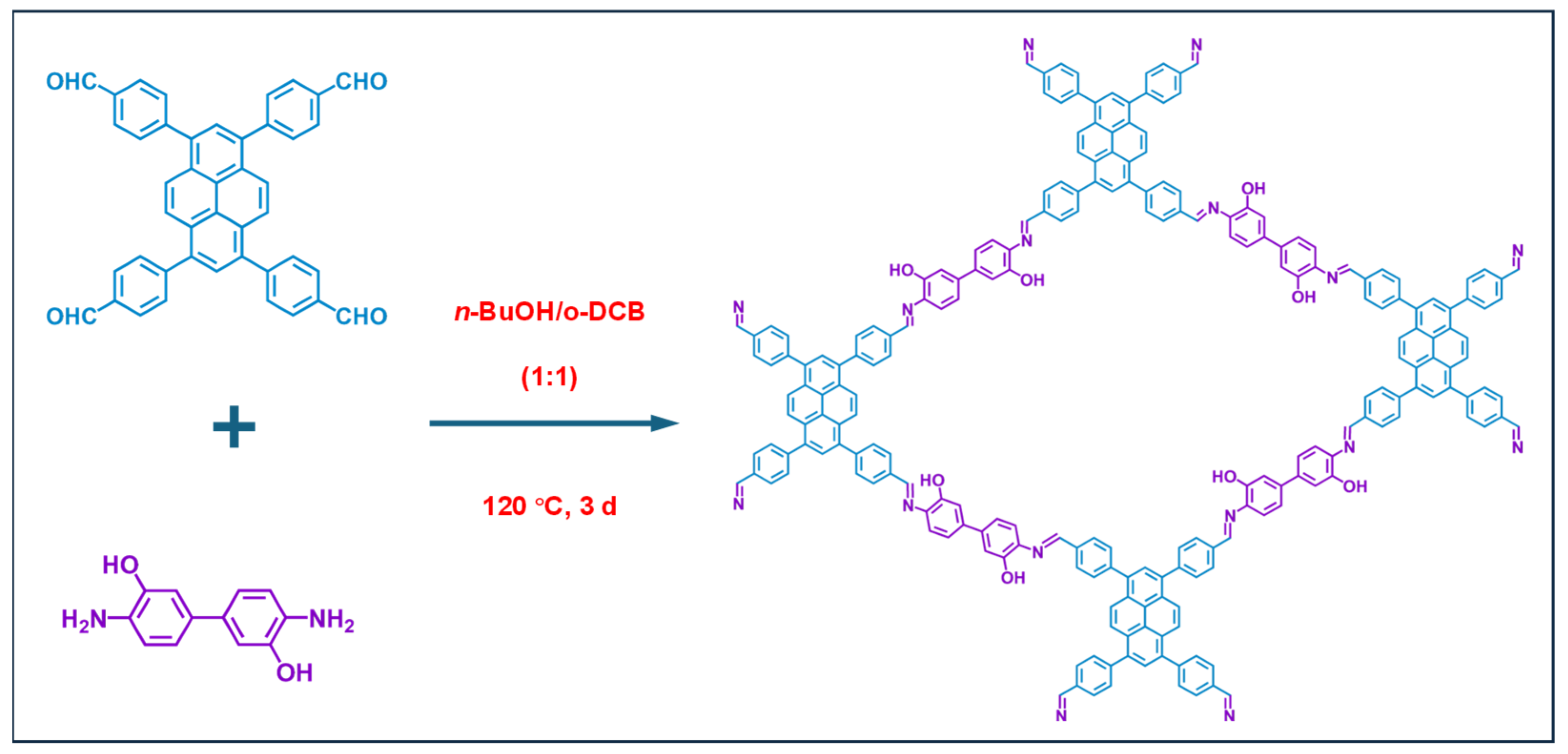
The synthesis process of PY−DHBD−COF is shown in Figure 1. The 2,2′-bipyridine-5,5′-dicarbaldehyde, 4,4′,4″,4‴-(pyrene-1,3,6,8-tetrayl) tetraaniline were mixed and then heated at 120 °C for 3 days. After cooling, the precipitate was collected by centrifugation, followed by washing with anhydrous THF five times and with acetone twice. The resulting powder was dried at 120 °C under vacuum conditions overnight, obtaining PY-BPY-COF [35].
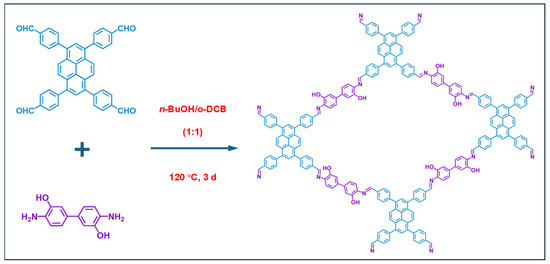
Figure 1.
The synthesis of PY−DHBD−COF by 2,2′-bipyridine-5,5′-dicarbaldehyde and 4,4′,4″,4‴-(pyrene-1,3,6,8-tetrayl) tetraaniline and the top view of the relaxed structure.
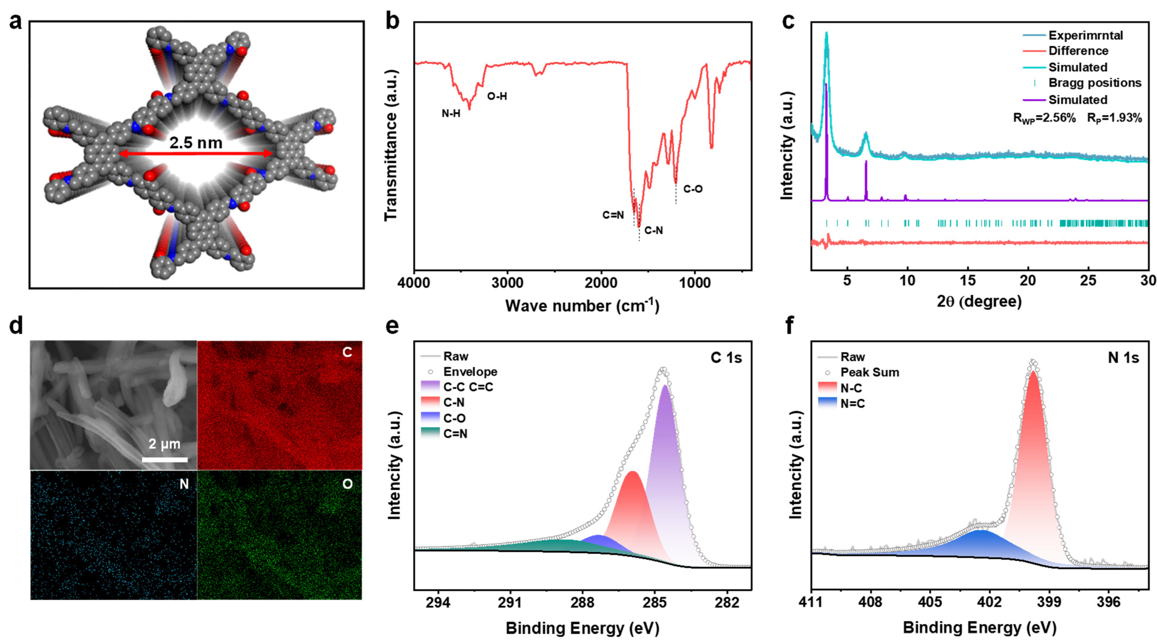
The synthesized PY−DHBD−COF was analyzed via Fourier transform infrared (FT-IR) spectroscopy (Figure 2b). The characteristic signals of C=N and C-N stretching at 1650 cm−1 and 1604 cm−1, respectively, demonstrated the formation of the β-ketoenamine connection. The signals at 1203, 3270, and 3409 cm−1 can be attributed to the C-O, O-H, and N-H stretches of PY−DHBD−COF, respectively, while other characteristic signals correspond to terminal residual groups [36]. The abundant hydroxyl and imine-N active sites can adsorb LiPSs. PXRD results revealed the typical crystalline pattern of PY−DHBD−COF, in which diffraction peaks at 3.27°, 4.88°, 6.56°, 9.76°, 13.30°, and 23.95° correspond to the crystal planes of (110), (020), (220), (330), (440), and (001), respectively (Figure 2c). The refinement indicated that the diffraction pattern of PY−DHBD−COF was consistent with that of an orthogonal lattice (Rp = 1.93%, Rwp = 2.56%), with cell parameters of a = 39.355 (3) Å, b = 41.382 (1) Å, and c = 3.894 (7) Å. This matches well with the ideal AA stacking model with the lowest stacking energy (Figure 2a, Figure S1 and Figure S2). The small pores can reduce the migration of LiPSs [37]. The SEM images of PY−DHBD−COF reveal that PY−DHBD−COF has a typical nanorod structure, with diameters ranging from 0.8 to 1 μm and a smooth surface (Figure S3a). Moreover, the elemental mapping images (Figure 2d) demonstrate that the three constituent elements (C, N, and O) are uniformly distributed in PY−DHBD−COF. Furthermore, the elements of PY−DHBD−COF were analyzed using X-ray photoelectron spectroscopy (XPS) (Figure S5). The spectra of C 1s and N 1s are shown in panels e and f in Figure 2e,f, respectively. The binding energy of C 1s at 285.9, 287.3, and 288.7 eV can be denoted as C-N, C-O, and C=N, respectively. The positions of the characteristic peaks of C-N and C=N bonds in the N 1s spectrum are 399.8 and 402.4 eV, respectively.
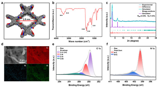
Figure 2.
(a) Stacking unit cell structure of PY−DHBD−COF. (b) Fourier transform infrared (FT−IR) spectrum of PY−DHBD−COF. (c) Experimental and simulated PXRD patterns of PY−DHBD−COF. (d) SEM images and the corresponding elemental mapping images of PY−DHBD−COF. (e) C 1s and (f) N 1s XPS spectra of PY−DHBD−COF.
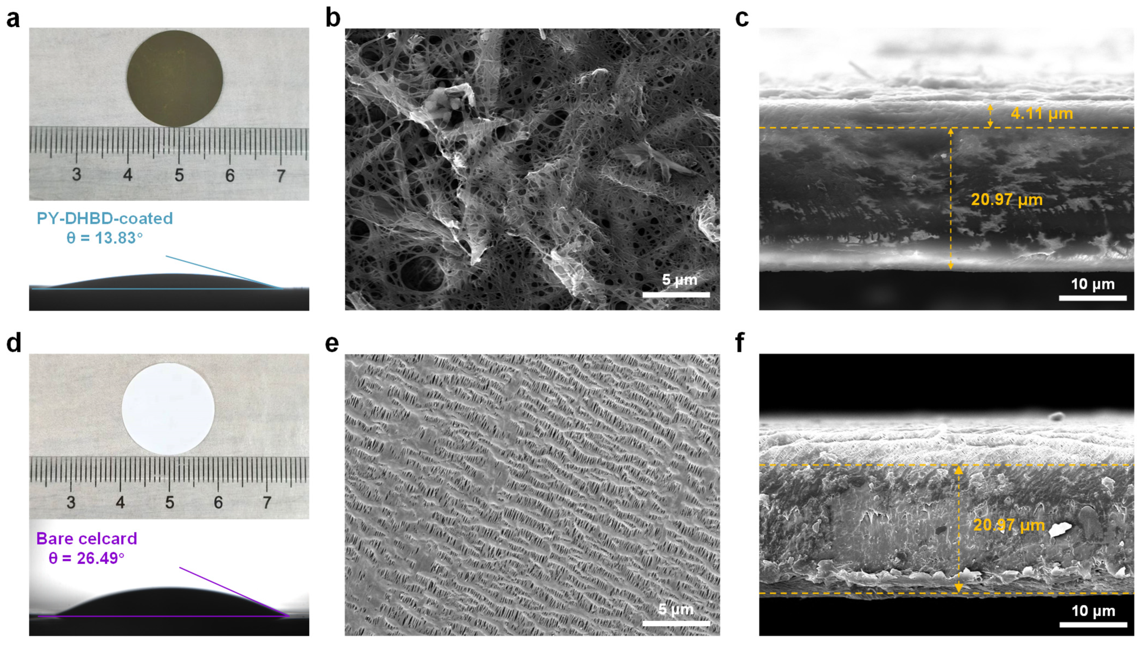
A PY−DHBD−COF-modified separator was prepared via vacuum-assisted self-assembly. Optical images of the PY−DHBD−COF-modified separator and bare Celgard 2500 PP separator, along with their respective contact angles with the electrolyte, are shown in Figure 3a,d. The strong affinity of PY−DHBD−COF for LiPSs, as well as its open porous structure, enhances the wetting properties of the separator when using an electrolyte, as evidenced by the reduced contact angle [38], which is beneficial to the migration of lithium ions during charging and discharging. To enhance the effect of PY−DHBD−COF on the cycling performance of LSBs, we introduced carbon nanotubes into PY−DHBD−COF when fabricating the PY−DHBD−COF-coated separator. Figure 3e illustrates the surface of bare Celgard 2500 PP separator with many pores (d > 100 nm). LiPSs can pass bare Celgard 2500 PP separator pores onto the surface of the Li metal. This phenomenon accounts for the severe shuttle effect of LiPSs in LSBs, leading to rapid capacity decay. The top-view SEM images (Figure 3b and Figure S3b) reveal that PY−DHBD−COF forms a stable barrier and uniformly covers the voids on the surface of the PP separator. The cross-sectional SEM images of the separator are shown in Figure 3c,f. The bare Celgard 2500 PP separator exhibits an average thickness of 20.97 μm. The thickness and areal density of the PY−DHBD−COF coating are 4.11 μm and 0.25 mg cm−2, respectively. Compared to metallic compounds, COF materials can maximize their advantage of being inherently lightweight, which is crucial for enhancing the overall energy density of LSBs.
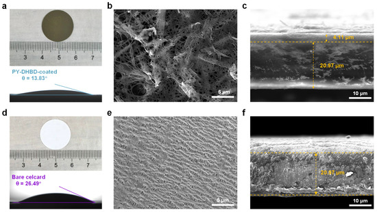
Figure 3.
Optical images and contact angles with the electrolytes of (a) the PY−DHBD−COF-modified separator and (d) the bare Celgard 2500 PP separator. Top-view SEM images of (b) the PY−DHBD−COF-modified separator and (e) the bare Celgard 2500 PP separator. Cross-sectional SEM images of (c) the PY−DHBD−COF-modified separator and (f) the bare Celgard 2500 PP separator.
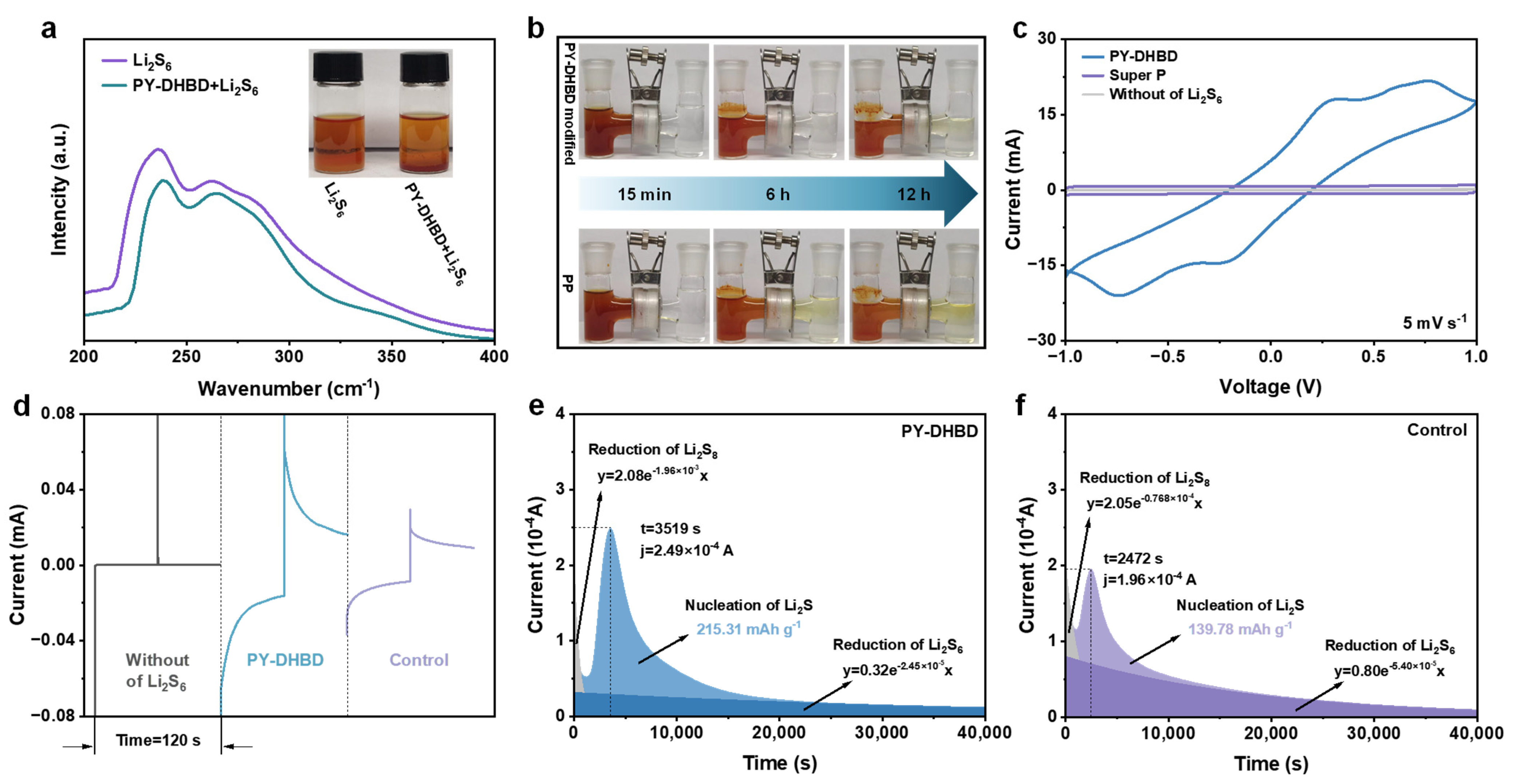
To evaluate the adsorption capacity of PY−DHBD−COF material on LiPS, 5 mg of COF powder was immersed in 5 mL of 2 mM the Li2S6 solution (a typical soluble LiPS in Li-S batteries). The optical photograph in Figure 4a and Figure S5 shows that the solution containing PY−DHBD−COF becomes lighter in color after the adsorption of Li2S6. The UV-vis spectra of the supernatant showed less residual Li2S6, which indicated that PY−DHBD−COF had a better adsorption effect on LiPS. As shown in Figure 4b, the H-type cell with a COF composite separator maintains the clear and transparent color of the opposite chamber even after 12 h, confirming the excellent polysulfide shielding effect of PY−DHBD−COF, which is consistent with the above results. This rational ionic conditioning is expected to favor the redox of sulfur and lithium, as well as the overall electrochemistry of Li-S batteries. In contrast, the originally transparent chamber showed a yellowish color after 12 h in the PP separator-based H-cells, which was attributed to the failure of the high-porosity PP separator to block the penetration of polysulfides. The LiPSs redox kinetics was investigated in a Li2S6 symmetric cell, where the electrodes of the symmetric cells were carbon cloths (CCs), loaded with either COF or Super P. The cyclic voltammetry (CV) curves of the cell treated with PY−DHBD−COF and Super P are shown in Figure 4c. Compared with the control Super P, the CV curves of COF cells showed more distinct two-pair redox peaks and higher current peaks, indicating improved polysulfide conversion. The chronoamperometry curve of the COF -based symmetric cell with Li2S6 electrolyte shows a more obvious current response than that of the control cell and blank electrolyte (Figure 4d), which confirms that the current is generated by the lithiation–delithiation process rather than the space double layer. The conversion of LiPSs into solid Li2S is an essential electrochemical reaction in LSBs, representing nearly three-quarters of the entire theoretical specific capacity. In this regard, we assessed Li2S nucleation kinetics based on the potentiostatic discharge curves of different cells at 2.05 V. Figure 4e,f show that the nucleation specific capacity of the cell with COF is 215 mAh g−1, which is markedly higher than that of the control electrode (140 mAh g−1). All the results indicate the high catalytic activity of PY−DHBD−COF in LiPS conversion.

Figure 4.
(a) Optical pictures of Li2S6 adsorption experiments and corresponding UV-vis spectra of Li2S6 solution after adsorption. (b) Polysulfide diffusions in H-type cells based on different separators. (c) CV curves and (d) chronoamperometric curves of different symmetric cells. (e) Potentiostatic discharge profiles of Li2S8 solution at 2.05 V on (e) PY−DHBD−COF and (f) control (Super P) electrodes.
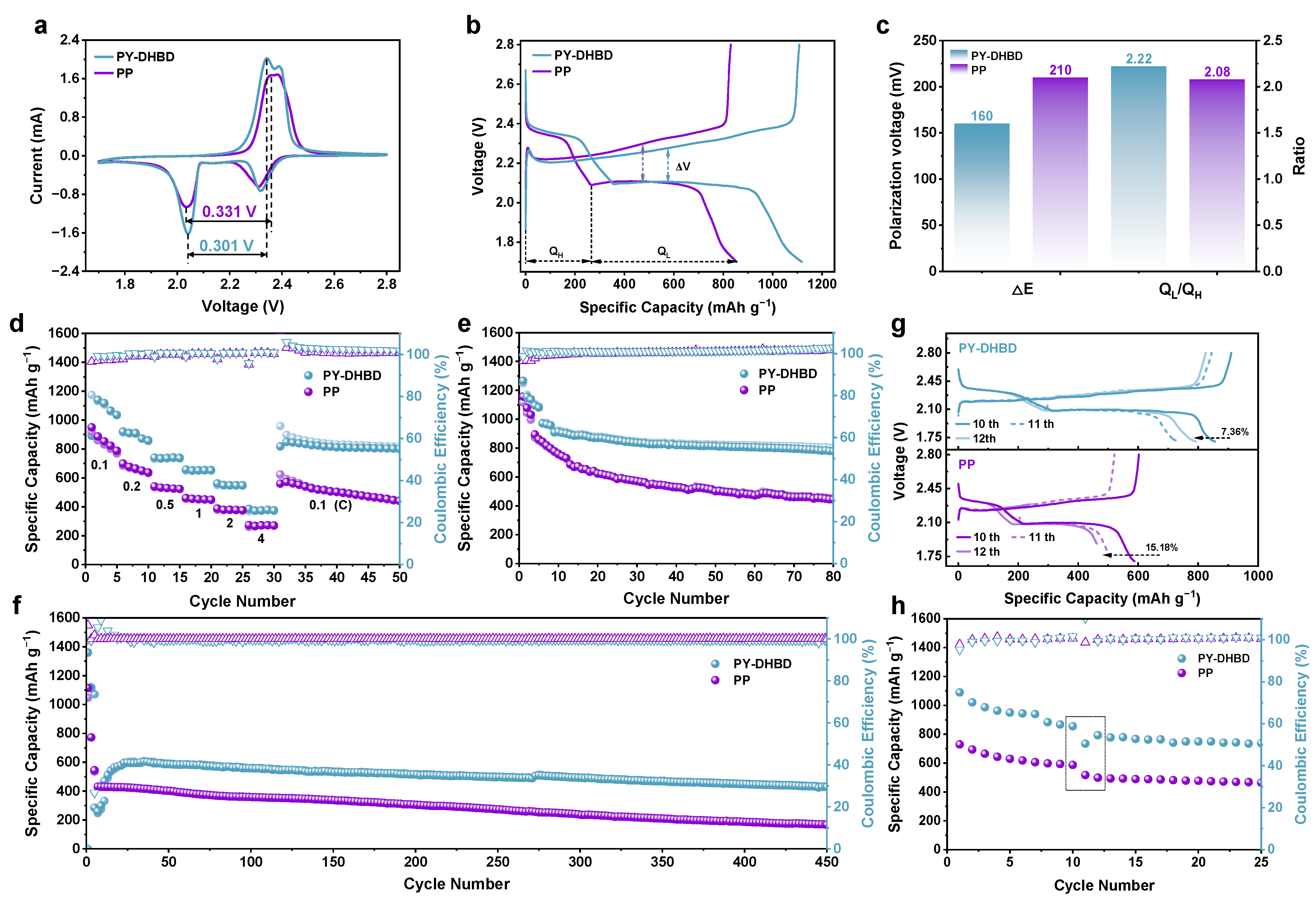
We tested the electrochemical performance of LSBs with a PY−DHBD−COF-modified separator and a bare Celgard 2500 PP separator. Figure 5a compares the CV curves of LSBs with a PY−DHBD−COF-modified separator and a bare Celgard 2500 PP separator at a scan rate of 0.1 mV s−1. All LSBs exhibit two reduction peaks and one oxidation peak. Two reduction peaks, namely, at ∼2.35 V and ∼2.05 V, represented the multi-step reduction of S8 to soluble LiPSs (Li2Sx, 4 ≤ x ≤ 8) and its further reduction to Li2S2/Li2S [39]. The oxidation peak at ∼2.45 V is attributed to the complex conversion process of Li2S into S8 [40]. The peak current density of the LSBs with PY−DHBD−COF-modified separator is higher than that of LSBs with a bare Celgard 2500 PP separator. The voltage polarization between the second reduction peak and the oxidation peak of the LSBs with the PY−DHBD−COF-modified separator is 0.301 V, which is lower than the 0.331 V observed in LSBs with the bare Celgard 2500 PP separator. This indicates excellent electrochemical activity and rapid reaction kinetics for the LSBs with the PY−DHBD−COF-modified separator. It is worth noting that, compared to the CV curve of PP-based LSBs, which only exhibits one oxidation peak, the CV curve of PY-DHBD-modified LSBs shows two pairs of distinct oxidation reduction peaks, further indicating the improvement in LiPSs reaction kinetics. The GCD curves, corresponding to different separator LSBs at a low current density of 0.1 C, are shown in Figure 5b. Here, QH corresponds to the solid–liquid conversion process capacity observed in the transformation from Li2Sx (4 ≤ x ≤ 8) to Li2S2, while QL corresponds to the liquid–solid–solid conversion process capacity observed in the transformation from Li2S2 to/Li2S (H and L represent the high and low plateaus in the discharge curves, respectively). Compared to the original PP LSB, the initial charging activation overpotential (ΔV) for PY-DHBD LSB is much lower (160 mV, compared to 210 mV for PP LSB), and the calculated QL/QH ratios for PY-DHBD and the PP separator LSBs are 2.22 and 2.08 (Figure 5c), respectively, further indicating that PY−DHBD−COF can effectively accelerate LPS conversion. This is also consistent with the lower resistance of the PY-DHBD separator compared to the original PP separator (Figure S6). Figure 5d illustrates the rate performance of LSBs with different separators. The initial discharge specific capacity of the LSBs with PY−DHBD−COF-modified separators is 1140 mAh g−1 at 0.1 C, while that of LSBs with bare Celgard 2500 PP separators is 918 mAh g−1. Even at 0.2, 0.5, 1.0, 2.0, and 4.0 C, the discharge specific capacity of LSBs with PY−DHBD−COF-modified separator remains at 971, 736, 651, 548, and 373 mAh g−1; these are higher values than that of LSBs with bare Celgard 2500 PP separators (664, 529, 452, 378, and 271 mAh g−1). The galvanostatic charge–discharge (GCD) curves of LSBs with different separators, operated at current densities from 0.1 to 4.0 C, are shown in Figure S7a,b. The appearance of two cathode plateaus and one anode plateau is consistent with the CV curves. As the current density increases, the reaction rate becomes faster, which leads to the accumulation of reaction intermediates and increases the electrochemical polarization. The cycling performance of LSBs with different separators at 0.2 C is shown in Figure 5e. The LSBs with an PY−DHBD−COF-modified separator shows an initial discharge specific capacity of 1266 mAh g−1 and maintains a stable discharge capacity of 778 mAh g−1 after 80 cycles, which is much higher than that of LSBs with bare Celgard 2500 PP separators (444 mAh g−1). To further study the long-term cycling performance, the LSBs with different separators were tested at 2.0 C for 450 cycles (Figure 5f). The LSBs with PY−DHBD−COF-modified separator exhibited a rapid capacity drop in the initial two cycles at 2 C after 5 cycles of activation at 0.1 C, which may be attributed to the insufficient activation. However, the capacity increases in the subsequent cycles and reaches the maximum (602 mAh g−1) at the 26th cycle. The LSBs maintain a high stable specific capacity of 429 mAh g−1 after 450 cycles with a low capacity loss of only 0.06% per cycle from the 26th to the 450th cycle. In contrast, the LSBs with a bare Celgard 2500 PP separator only provide a specific capacity of 168 mAh g−1 after 450 cycles.
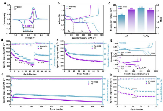
Figure 5.
(a) CV curves of LSBs based on different separators at 0.1 mV s−1 sweep speed. (b) Charge and discharge voltage curve at 0.1 C current and (c) corresponding median-capacity voltage polarization and capacity comparison of two discharge plateaus at 0.1 C (QH stands for high plateau, QL stands for low plateau). (d) Rate performance of LSBs with different separators at current density ranging from 0.1 C to 4 C. (e) Cycling stability of LSBs with different separators at a rate of 0.2 C. (f) Long-cycle life tests of LSBs with different separators at a rate of 2 C (activated at 0.1 C in the first 5 cycles). (g) Self-discharge test (0.2 C cycle to the 10th cycle start; stand 72 h; continue cycle). (h) Comparison of capacity changes after 3 days of standing (from 10th to 12th turn of the voltage curve color from dark to light, where 11th turn is dotted line).
Furthermore, the LSBs were cycled for 10 cycles at 0.2 C and then were discharged at 2.1 V (near the second discharge plateau) and 0.2 C. This was followed by standing for 72 h to test the self-discharge resistance (Figure 5g,h). Both LSBs exhibited capacity loss after standing for 72 h. The LSBs with PY−DHBD−COF-modified separators exhibited a low capacity decay of 7.36% (10th cycle versus the 12th cycle), which was much lower than that of the LSBs with bare Celgard 2500 PP (15.18%). The capacity of LSBs with PY−DHBD−COF-modified separators recovered from 735 mAh g−1 in the 11th cycle to 793 mAh g−1 in the 12th cycle, but the capacity of the LSBs with bare Celgard 2500 PP continued to decrease from 518 mAh g−1 in the 11th cycle to 498 mAh g−1 in the 12th cycle. These results confirm that PY−DHBD−COF modification can mitigate the shuttle effects and help to resist resist self-discharge behavior.
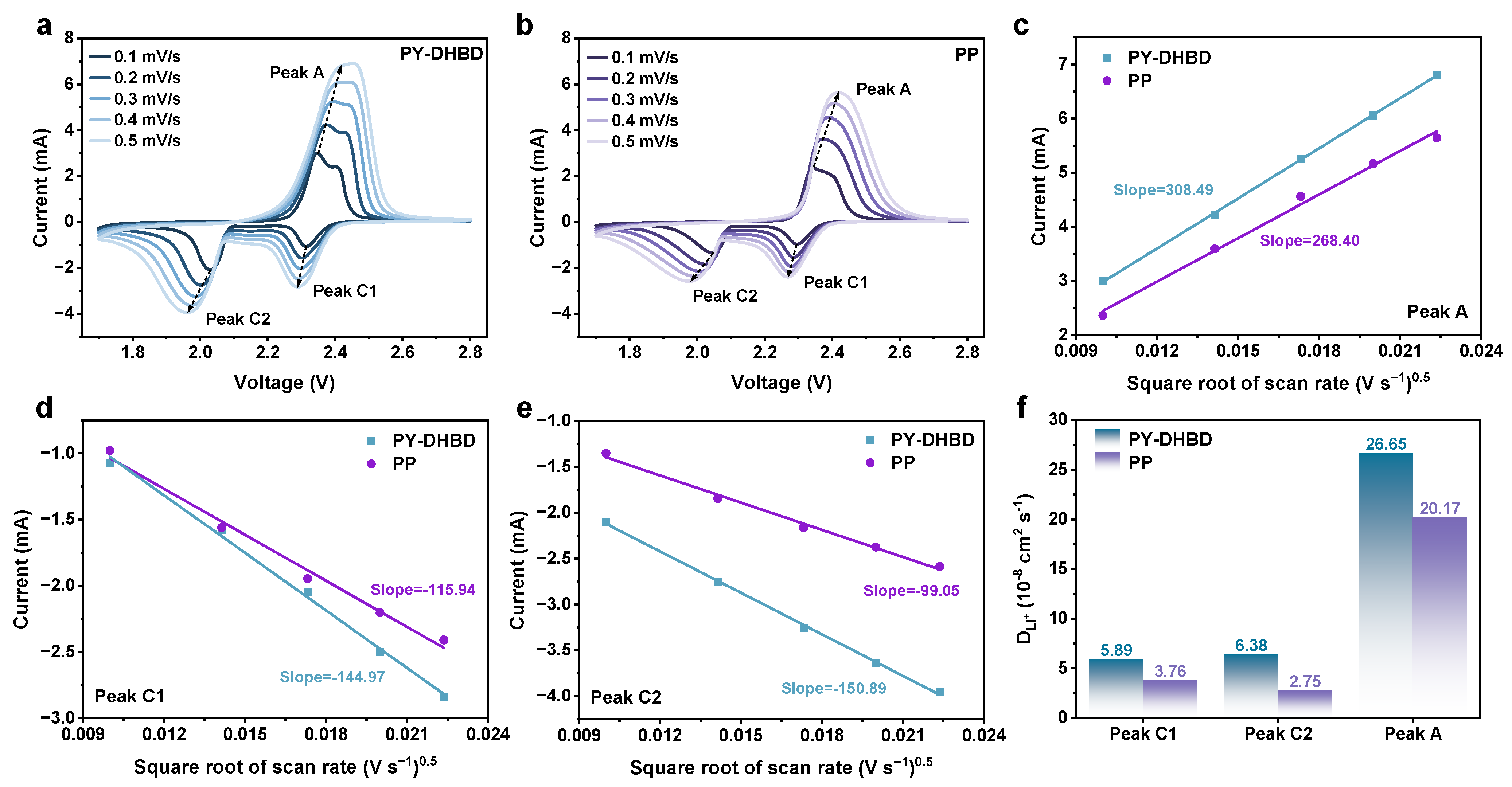
As we all know, the ion diffusion rate is another important factor affecting the kinetics of polysulfides. Based on this, the Li+ diffusion coefficient was further analyzed via CV at different scanning rates (Figure 6). The cathodic and anodic scans typically include two reduction peaks (C1, C2) and two poorly differentiated oxidation peaks (usually manifested as only one peak—A), respectively, and the peak currents at different scan rates are highly relevant to the linear fitting results. The lithium diffusion coefficients (DLi+) of the COF separator, calculated for all three peaks, are significantly higher than those of the pure PP separator. In particular, the DLi+ of peak C2 (key reaction steps for Li2S deposition) is calculated to be 6.38 × 10⁻⁸ cm2 s−1 for PY−DHBD−COF-modified LSB, which is 2.32 times higher than that of PP (2.75 × 10⁻⁸ cm2 s−1). This is mainly due to the selectively accelerated migration of Li+, caused the highly ordered pore structure of PY−DHBD−COF.

Figure 6.
CV profiles at different scan rates with (a) PY−DHBD−COF-modified separators and (b) PP separator-based LSBs. Plot of peak current versus square root of scan speed (v1/2) for different separator-based LSBs at (c) oxidative peak A, (d) reductive peak C1, and (e) reductive peak C2, with dashed lines indicating the fitted results. (f) DLi+, calculated by the linear relationship between peak current and square root of scan rates.
In order to examine the performance of lithium–sulfur batteries with PY-DHBD-modified diaphragms under kinetically limiting conditions, LSBs with loadings of 2 mg cm−2 and 2.8 mg cm−2 and E/S ratios of 12.7 µL mg−1 and 9.1 µL mg−1, respectively, were assembled (Figure S8). Under high-sulfur loading conditions, the LSB loaded with 2 mg cm−2 maintained a high specific capacity of 530 mAh g−1 after 200 cycles of stable cycling at 1 C. When the mass loading was increased to 2.8 mg cm−2 with an E/S ratio of 9.1 µL mg−1, the initial specific capacity of the cell at 0.5 C was 1,026 mA h g−1, with a capacity retention of 59.5% after 100 cycles. To better verify the mitigation of the shuttle effect, which is caused by the PY-DHBD COF-modified separator, and the protection of the lithium anode, LSBs were dismantled after 200 cycles at 2 C. As shown in Figure S9, the optical photographs and SEM images of the lithium anode revealed that the PY-DHBD COF coating showed good adherence to the PP separator substrate after cycling and generally maintained good morphology. Additionally, the lithium anode of the LSBs with PY-DHBD COF-modified separators exhibited surface cracking after cycling, but it remained relatively smooth and even overall. In contrast, the lithium anode of the LSBs with PP separators showed severe surface cracking, with extensive grooves and unevenness. This observation was consistent with the deeper color observed in the optical photographs relative to the cathode. Comparing the surface morphology of the lithium anodes from LSBs with the two types of separators after cycling shows that the PY-DHBD COF-modified separator effectively alleviates the negative impact of the polysulfide ‘shuttle effect’ on the lithium anode. SEM images of the separator facing the lithium anode side after cycling, along with the sulfur content and distribution maps (Figures S10 and S11), also confirm that the COF coating effectively hinders the shuttle effect. EDS analysis shows that the residual particulate matter on the backside of both separators mainly consists of lithium-related lithium–sulfide and lithium–fluoride products. The lower sulfur content on the backside of the PY-DHBD COF-modified separator indicates that there are fewer polysulfides passing through, while the higher fluorine content suggests a more stable SEI layer on the lithium anode surface (Figures S12 and S13). Overall, the PY-DHBD COF-modified separator effectively mitigates the shuttle effect and protects the anode, thereby enhancing the utilization of active materials on the sulfur cathode side and maintaining better cycling stability.
3. Materials and Methods
3.1. Synthesis of PY−DHBD−COF and Modified PP Separator
A mixture of 2,2′-bipyridine-5,5′-dicarbaldehyde (0.08 mmol, 17 mg) and 4,4′,4″,4‴-(pyrene-1,3,6,8-tetrayl) tetraaniline (0.04 mmol, 22.6 mg) in an n-butyl alcohol (n-BuOH)/o-dichlorobenzene (o-DCB)/6 M acetic acid (5/5/1 by vol., 2.2 mL) mixture was degassed using three freeze–pump–thaw cycles in a Pyrex tube (20 mL). The sealed tube was then heated at 120 °C for 3 days. After cooling, the precipitate was collected by centrifugation, followed by washing with anhydrous THF five times and with acetone twice. The resulting powder was dried at 120 °C under vacuum conditions overnight, yielding PY-BPY-COF with a yield of 62%.
The PY−DHBD−COF-modified separator was prepared using a simple vacuum self-assembly method. PY−DHBD−COF, single-walled carbon nanotubes (CNTs), and polyvinylidene fluoride (PVDF) were mixed at a mass ratio of 8:1:1 in N-methyl-2-pyrrolidone (NMP) to form a homogeneous suspension. The suspension was then uniformly poured onto the Celgard 2500 PP separator, using a filtration apparatus for vacuum filtration. The modified separator was dried overnight at 60 °C and then cut into small discs with diameters of 19 mm. The overall thickness of the modified separator was about 15 μm, with PY−DHBD−COF mass loading of approximately 0.25 mg cm−2.
3.2. Characterization
The structure of samples was recorded via powder X-ray diffraction (PXRD, Bruker AXS D8 Advance), with Cu Kα-type radiation (40 kV, 40 mA). The simulated PXRD patterns were determined by the Reflex module. Fourier transform infrared (FTIR) spectra were recorded in transmission mode on a Nicolet Impact 410 spectrometer in the range of 400–4000 cm−1. The simulations of the possible structures were carried out in the Accelrys Material Studio 7.0 software package. A scanning electron microscope (SEM, JEOL-JSM-7800F) and transmission electron microscope (TEM, JEOL-JEM-2100) were used to study the morphology and crystal structure of the samples.
3.3. Preparation of Cathode
The sulfur cathode was prepared using the melt diffusion method. Typically, sulfur and Ketjen Black (KB) were thoroughly ground to a 3:1 mass ratio and annealed at 155 °C under Ar2 for 12 h. The S/KB composite contained about 75% sulfur. We mixed the S/KB composite, Super P, and LA133 binder at a mass ratio of 7:2:1 in water/ethanol (10:1, v/v) to form a slurry, which was then evenly cast onto nickel foam and dried at 60 °C for 12 h to form cathode with a sulfur mass loading of 1.2 mg cm−2.
3.4. Electrochemical Performance Test
Lithium metal was used as the anode. We used 1.0 M LiTFSI in DOL and DME (v:v = 1:1) with 2.0 wt% LiNO3 as the electrolyte. Electrochemical tests were performed by assembling 2025 coin-type half-cells in an argon-filled glove box in which the O2 and H2O content was less than 0.1 ppm. The galvanostatic charge/discharge measurement was conducted on a land system within a voltage window of 1.7–2.8 V. Cyclic voltammetry (CV) tests and electrochemical impedance (EIS) tests were performed on a CHI600e electrochemical workstation. The specific capacity was calculated based on the weight of the sulfur. For each cell, the electrolyte/sulfur (E/S) rate was controlled to be around 15 μL mg−1.
3.5. Visualized Adsorption of Li2S6 Experiments
Adsorption measurements were carried out to investigate the polysulfide capture capability of the porous composite. A Li2S6 solution (0.1 M, brown) was prepared by dissolving Li2S and S in a molar ratio of 1:5 in a mixture of 1,3-dioxolane/1,2-dimethoxyethane (DOL/DME, 1:1 by volume). This solution was used as the pristine polysulfide source. Overall, 5 mg of PY−DHBD−COF powders was added into 5 mL of Li2S6 solution (2 mM), respectively. The blank PY−DHBD−COF and Li2S6 solution with the same concentration was used as the reference. The whole process was performed in an argon-filled glove box, with the content of H2O and O2 both below 0.01 ppm. After static cultivation for 8 h, the supernatant was examined by ultraviolet–visible (UV-vis) absorption spectroscopy.
3.6. Symmetric Cell Measurements
The electrodes (PY−DHBD−COF and Super P) used for symmetric cells were prepared by the dropping method, and the carbon cloths (CCs) were used as current collectors. Two pieces of the same electrode (loading about 1 mg cm−2) were directly used as working and counter electrodes. Overall, 30 μL of Li2S6 (0.5 M) with 1 M LiTFSI in DOL/DME was used as the electrolyte. The CV curves of symmetric cells were assessed at a scan rate of 10 mV s−1 within a voltage window of 1.0 V and −1.0 V.
3.7. Li2S Nucleation Experiments
Li2S precipitation experiments were carried out with a 0.25 M Li2S8 catholyte obtained by reacting Li2S and S at a molar ratio of 1:7 in a tetraethylene glycol dimethyl ether (TEGDME) solution with 1.0 M LiTFSI. The cathodes were fabricated in the same way as electrodes are prepared for symmetric cells. Lithium foils were used as anodes and common PP separators were used. Overall, 15 μL of Li2S8 catholyte was dropped onto the cathode, and then 20 μL conventional electrolyte (TEGDME solution with 1.0 M LiTFSI) was dropped onto the lithium anode side. The cells were first galvanostatically discharged at a current of 0.112 mA until the voltage was 2.06 V; this was then kept at 2.05 V for Li2S nucleation and growth.
3.8. Lithium-Ion Diffusion Coefficient
The lithium-ion diffusion coefficient DLi+ (cm2 s−1) is evaluated via the cyclic voltammetry method and calculated according to the Randles–Sevick equation:
where Ip(A) is the peak current value, n represents the number of electrons of in the reaction (for Li-S batteries, n = 2), A (cm2) indicates the electrode area (here is 0.7854 cm2), CLi+ (mol mL−1) means the lithium-ion concentration in the electrolyte, and v stands for the scanning rate (V s−1).
Ip = 2.69 × 10⁵n1.5ADLi+0.5CLi+v0.5
4. Conclusions
In summary, we designed and synthesized a COF (PY−DHBD−COF) and applied it in order to modify the separators of LSBs. Compared to the bare Celgard 2500 PP separator, the abundant O and imine-N of PY−DHBD−COF’s hydroxyl groups not only serve as active sites for chemically trapping LiPSs, but also facilitate electrolyte wetting and Li+ transport. Therefore, the LSBs with PY−DHBD−COF-modified separator exhibited excellent electrochemical performance. The initial discharge specific capacity of the LSBs with PY−DHBD−COF-modified separator is 1140 mAh g−1 at 0.1 C. At 0.2, 0.5, 1.0, 2.0, and 4.0 C; the discharge specific capacity of LSBs with PY−DHBD−COF-modified separators remains 971, 736, 651, 548, and 373 mAh g−1. The LSBs with PY−DHBD−COF-modified separator maintain a stable discharge capacity of 778 mAh g−1 after 80 cycles, which is much higher than that of LSBs with made with bare Celgard 2500 PP separator (444 mAh g−1). LSBs maintain a high stable specific capacity of 429 mAh g−1 after 450 cycles, with a low capacity loss of only 0.06% per cycle from the 26th to the 450th cycle. Postmortem analysis of the separator and lithium anode after cycling indicates that the PY-DHBD COF coating helps in mitigating the shuttle effect and provides protection to the anode. This study may inspire further exploration of advanced COFs for the development of high-performance LSBs.
Supplementary Materials
The following supporting information can be downloaded at: https://www.mdpi.com/article/10.3390/inorganics12080218/s1, Figure S1: AA Stacking Layer Structure of PY-DHBD-COF; Figure S2: Optimal superposition model of PY-BPY-COF AA in different directions; Figure S3: Scanning electron microscope (SEM) image of (a)PY-DHBD-COF and (b) PY-DHBD -coated composite separator surface; Figure S4: XPS survey spectra of PY-DHBD-COF; Figure S5: Optical photos of the Li2S6 adsorption experiment (In addition to testing the adsorption of PY-DHBD-COF on Li2S6, its own solubility in DOL/DME (1; 1, the color change of v/v) solvent is also compared.); Figure S6: EIS test of PY-DHBD-coated and PP LSBs; Figure S7: The charge and discharge voltage curve of (a) original PP separator and (b) PY-DHBD-COF modified separator LSBs from 0.1 C to 4 C; Figure S8: Cycling stability of LSBs with PY-DHBD-COF modified separator at sulfur loading of 2.0 and 2.8 mg cm-2, respectively; Figure S9: Optical photographs of dismantled LSBs after cycling and SEM images of the lithium anode. (a-c) PY-DHBD-COF modified separator and (d-f) PP separator; Figure S10: SEM images of the anode-facing side of the PY-DHBD-COF modified separator from dismantled LSBs after cycling and the corresponding elemental mapping images. (Due to the poor conditions during sample delivery and testing, the dismantled Li anode was severely oxidized when taking SEM images, resulting in a high oxygen content. However, by comparing the sulfur content on the backside of the separator, it can still be observed that the COF coating effectively mitigates the shuttle effect compared to the pure PP separator.); Figure S11: SEM images of the anode-facing side of the PP separator from dismantled LSBs after cycling and the corresponding elemental mapping images; Figure S12: Elemental distribution map total spectrum of Figure S10; Figure S13: Elemental distribution map total spectrum of Figure S11.
Author Contributions
Writing—original draft, H.H.; Investigation and Resources, W.W.; Writing—review & editing, X.G. All authors have read and agreed to the published version of the manuscript.
Funding
This research received no external funding.
Data Availability Statement
The original contributions presented in the study are included in the article/supplementary material, further inquiries can be directed to the corresponding author/s.
Conflicts of Interest
The authors Hong He, Wei Wang and Xiaobei Guo were employed by Nanjing Fiberglass Research and Design Institute Co., Ltd. The authors declare that the research was conducted in the absence of any commercial or financial relationships that could be construed as a potential conflict of interest. Nanjing Fiberglass Research and Design Institute Co., Ltd. had no role in the design of the study; in the collection, analyses, or interpretation of data; in the writing of the manuscript, and in the decision to publish the results.
References
- Yang, Z.; Guo, Z.; Wang, X.; Lu, W.; Wang, Q.; Zhao, Y.; Yao, M.; Gao, P.; Zhang, D.; Du, F. Bi-functional material SnSSe/rGO with anionic vacancies serves as a polysulfide shuttling blocker and lithium dendrite inhibitor. Energy Storage Mater. 2024, 67, 103276. [Google Scholar] [CrossRef]
- Song, M.; Liu, Y.; Hong, J.; Wang, X.; Huang, X. Boosting bidirectional conversion of polysulfide driven by the built-in electric field of MoS2/MoP Mott-Schottky heterostructures in lithium–sulfur batteries. J. Adv. Ceram. 2023, 12, 1872–1888. [Google Scholar] [CrossRef]
- Zhu, Q.; Xu, H.-F.; Shen, K.; Zhang, Y.-Z.; Li, B.; Yang, S.-B. Efficient polysulfides conversion on Mo2CTx MXene for high-performance lithium-sulfur batteries. Rare Met. 2022, 41, 311–318. [Google Scholar] [CrossRef]
- Liu, C.; Qiu, Y.; Liu, Y.; Xu, K.; Zhao, N.; Lao, C.; Shen, J.; Chen, Z. Novel 3D grid porous Li4Ti5O12 thick electrodes fabricated by 3D printing for high performance lithium-ion batteries. J. Adv. Ceram. 2022, 11, 295–307. [Google Scholar] [CrossRef]
- Bai, Y.; Li, J.; Lu, H.; Liu, J.; Ma, C.; Wang, B.; Zhao, X.; Deng, J. Ultrafast high-temperature sintering of high-entropy oxides with refined microstructure and superior lithium-ion storage performance. J. Adv. Ceram. 2023, 12, 1857–1871. [Google Scholar] [CrossRef]
- Gao, F.; Yue, X.-A.; Xu, X.-Y.; Xu, P.; Zhang, F.; Fan, H.-S.; Wang, Z.-L.; Wu, Y.-T.; Liu, X.; Zhang, Y. A N/Co co-doped three-dimensional porous carbon as cathode host for advanced lithium-selenium batteries. Rare Met. 2023, 42, 2670–2678. [Google Scholar] [CrossRef]
- Zhou, J.; Sun, S.; Zhou, X.; Rao, X.; Xu, X.; Zhang, Z.; Pan, Z.; Wang, Q.-C.; Wang, Z.; Wu, Y.; et al. Defect engineering enables an advanced separator modification for high-performance lithium-sulfur batteries. Chem. Eng. J. 2024, 487, 150574. [Google Scholar] [CrossRef]
- Li, S.; Peng, Z.; Fu, X. Zn0.5Co0.5Mn0.5Fe0.5Al0.5Mg0.5O4 high-entropy oxide with high capacity and ultra-long life for Li-ion battery anodes. J. Adv. Ceram. 2023, 12, 59–71. [Google Scholar] [CrossRef]
- He, Y.; Chang, Z.; Wu, S.; Qiao, Y.; Bai, S.; Jiang, K.; He, P.; Zhou, H. Simultaneously Inhibiting Lithium Dendrites Growth and Polysulfides Shuttle by a Flexible MOF-Based Membrane in Li-S Batteries. Adv. Energy Mater. 2018, 8, 1802130. [Google Scholar] [CrossRef]
- Yang, W.-H.; Ni, Z.-C.; You, D.; Hou, J.-Y.; Deng, B.-N.; Huang, R.-W.; Sun, S.-G.; Zhao, J.-B.; Li, X.; Zhang, Y.-Y.; et al. Multifunctional sulfur-immobilizing GO/MXene aerogels for highly-stable and long-cycle-life lithium-sulfur batteries. Rare Met. 2023, 42, 2577–2591. [Google Scholar] [CrossRef]
- Tu, S.; Chen, X.; Zhao, X.; Cheng, M.; Xiong, P.; He, Y.; Zhang, Q.; Xu, Y. A Polysulfide-Immobilizing Polymer Retards the Shuttling of Polysulfide Intermediates in Lithium–Sulfur Batteries. Adv. Mater. 2018, 30, 1804581. [Google Scholar] [CrossRef] [PubMed]
- Xia, S.; Song, J.; Zhou, Q.; Liu, L.; Ye, J.; Wang, T.; Chen, Y.; Liu, Y.; Wu, Y.; van Ree, T. A Separator with Double Coatings of Li4Ti5O12 and Conductive Carbon for Li-S Battery of Good Electrochemical Performance. Adv. Sci. 2023, 10, 2301386. [Google Scholar] [CrossRef]
- Wang, J.; Han, W.-Q. A Review of Heteroatom Doped Materials for Advanced Lithium–Sulfur Batteries. Adv. Funct. Mater. 2022, 32, 2107166. [Google Scholar] [CrossRef]
- Guan, L.; Hu, H.; Li, L.; Pan, Y.; Zhu, Y.; Li, Q.; Guo, H.; Wang, K.; Huang, Y.; Zhang, M.; et al. Intrinsic Defect-Rich Hierarchically Porous Carbon Architectures Enabling Enhanced Capture and Catalytic Conversion of Polysulfides. ACS Nano 2020, 14, 6222–6231. [Google Scholar] [CrossRef] [PubMed]
- Liu, W.; Luo, C.; Zhang, S.; Zhang, B.; Ma, J.; Wang, X.; Liu, W.; Li, Z.; Yang, Q.-H.; Lv, W. Cobalt-Doping of Molybdenum Disulfide for Enhanced Catalytic Polysulfide Conversion in Lithium–Sulfur Batteries. ACS Nano 2021, 15, 7491–7499. [Google Scholar] [CrossRef] [PubMed]
- Song, X.; Tian, D.; Qiu, Y.; Sun, X.; Jiang, B.; Zhao, C.; Zhang, Y.; Fan, L.; Zhang, N. Improving poisoning resistance of electrocatalysts via alloying strategy for high-performance lithium-sulfur batteries. Energy Storage Mater. 2021, 41, 248–254. [Google Scholar] [CrossRef]
- Cheng, Z.; Pan, H.; Zhong, H.; Xiao, Z.; Li, X.; Wang, R. Porous Organic Polymers for Polysulfide Trapping in Lithium–Sulfur Batteries. Adv. Funct. Mater. 2018, 28, 1707597. [Google Scholar] [CrossRef]
- Demir-Cakan, R.; Morcrette, M.; Nouar, F.; Davoisne, C.; Devic, T.; Gonbeau, D.; Dominko, R.; Serre, C.; Férey, G.; Tarascon, J.-M. Cathode Composites for Li–S Batteries via the Use of Oxygenated Porous Architectures. J. Am. Chem. Soc. 2011, 133, 16154–16160. [Google Scholar] [CrossRef]
- Stegbauer, L.; Zech, S.; Savasci, G.; Banerjee, T.; Podjaski, F.; Schwinghammer, K.; Ochsenfeld, C.; Lotsch, B.V. Tailor-Made Photoconductive Pyrene-Based Covalent Organic Frameworks for Visible-Light Driven Hydrogen Generation. Adv. Energy Mater. 2018, 8, 1703278. [Google Scholar] [CrossRef]
- Jiang, C.; Tang, M.; Zhu, S.; Zhang, J.; Wu, Y.; Chen, Y.; Xia, C.; Wang, C.; Hu, W. Constructing Universal Ionic Sieves via Alignment of Two-Dimensional Covalent Organic Frameworks (COFs). Angew. Chem. Int. Ed. 2018, 57, 16072–16076. [Google Scholar] [CrossRef] [PubMed]
- Wang, J.; Qin, W.; Zhu, X.; Teng, Y. Covalent organic frameworks (COF)/CNT nanocomposite for high performance and wide operating temperature lithium–sulfur batteries. Energy 2020, 199, 117372. [Google Scholar] [CrossRef]
- Zhang, F.-M.; Sheng, J.-L.; Yang, Z.-D.; Sun, X.-J.; Tang, H.-L.; Lu, M.; Dong, H.; Shen, F.-C.; Liu, J.; Lan, Y.-Q. Rational Design of MOF/COF Hybrid Materials for Photocatalytic H2 Evolution in the Presence of Sacrificial Electron Donors. Angew. Chem. Int. Ed. 2018, 57, 12106–12110. [Google Scholar] [CrossRef] [PubMed]
- Wu, Z.; Feng, L.; Luo, J.; Zhao, Y.; Yu, X.; Li, Y.; Wang, W.; Sui, Z.; Tian, X.; Chen, Q. Metalation of functionalized benzoquinoline-linked COFs for electrocatalytic oxygen reduction and lithium-sulfur batteries. J. Colloid Interface Sci. 2023, 650, 1466–1475. [Google Scholar] [CrossRef] [PubMed]
- Hu, B.; Xu, J.; Fan, Z.; Xu, C.; Han, S.; Zhang, J.; Ma, L.; Ding, B.; Zhuang, Z.; Kang, Q.; et al. Covalent Organic Framework Based Lithium-Sulfur Batteries: Materials, Interfaces, and Solid-State Electrolytes. Adv. Energy Mater. 2023, 13, 2203540. [Google Scholar] [CrossRef]
- Je, S.H.; Kim, H.J.; Kim, J.; Choi, J.W.; Coskun, A. Perfluoroaryl-Elemental Sulfur SNAr Chemistry in Covalent Triazine Frameworks with High Sulfur Contents for Lithium-Sulfur Batteries. Adv. Funct. Mater. 2017, 27, 1703947. [Google Scholar] [CrossRef]
- Lv, S.; Ma, X.; Ke, S.; Wang, Y.; Ma, T.; Yuan, S.; Jin, Z.; Zuo, J.-L. Metal-Coordinated Covalent Organic Frameworks as Advanced Bifunctional Hosts for Both Sulfur Cathodes and Lithium Anodes in Lithium–Sulfur Batteries. J. Am. Chem. Soc. 2024, 146, 9385–9394. [Google Scholar] [CrossRef] [PubMed]
- Sun, L.; Li, Z.; Zhai, L.; Moon, H.; Song, C.; Oh, K.-S.; Kong, X.; Han, D.; Zhu, Z.; Wu, Y.; et al. Electrostatic polarity-regulated, vinylene-linked cationic covalent organic frameworks as an ionic sieve membrane for long-cyclable lithium-sulfur batteries. Energy Storage Mater. 2024, 66, 103222. [Google Scholar] [CrossRef]
- Cai, S.; Ma, R.; Ke, W.; Zhang, H.; Liu, Y.; Jiao, M.; Tian, Y.; Fang, Y.; Wu, M.; Zhou, Z. Flower-like covalent organic frameworks as host materials for high-performance lithium-sulfur batteries. Chem. Eng. J. 2024, 491, 151979. [Google Scholar] [CrossRef]
- Li, J.; Jing, X.; Li, Q.; Li, S.; Gao, X.; Feng, X.; Wang, B. Bulk COFs and COF nanosheets for electrochemical energy storage and conversion. Chem. Soc. Rev. 2020, 49, 3565–3604. [Google Scholar] [CrossRef]
- Xu, J.; Zhang, H.; Yu, F.; Cao, Y.; Liao, M.; Dong, X.; Wang, Y. Realizing All-Climate Li-S Batteries by Using a Porous Sub-Nano Aromatic Framework. Angew. Chem. Int. Ed. 2022, 61, e202211933. [Google Scholar] [CrossRef]
- Cao, Y.; Liu, C.; Wang, M.; Yang, H.; Liu, S.; Wang, H.; Yang, Z.; Pan, F.; Jiang, Z.; Sun, J. Lithiation of covalent organic framework nanosheets facilitating lithium-ion transport in lithium-sulfur batteries. Energy Storage Mater. 2020, 29, 207–215. [Google Scholar] [CrossRef]
- Xu, J.; An, S.; Song, X.; Cao, Y.; Wang, N.; Qiu, X.; Zhang, Y.; Chen, J.; Duan, X.; Huang, J.; et al. Towards High Performance Li–S Batteries via Sulfonate-Rich COF-Modified Separator. Adv. Mater. 2021, 33, 2105178. [Google Scholar] [CrossRef] [PubMed]
- Yan, W.; Gao, X.; Yang, J.-L.; Xiong, X.; Xia, S.; Huang, W.; Chen, Y.; Fu, L.; Zhu, Y.; Wu, Y. Boosting Polysulfide Catalytic Conversion and Facilitating Li+ Transportation by Ion-Selective COFs Composite Nanowire for Li-S Batteries. Small 2022, 18, 2106679. [Google Scholar] [CrossRef] [PubMed]
- Li, Y.; Yang, L.; He, H.; Sun, L.; Wang, H.; Fang, X.; Zhao, Y.; Zheng, D.; Qi, Y.; Li, Z.; et al. In situ photodeposition of platinum clusters on a covalent organic framework for photocatalytic hydrogen production. Nat. Commun. 2022, 13, 1355. [Google Scholar] [CrossRef] [PubMed]
- Lu, Q.; Ma, Y.; Li, H.; Guan, X.; Yusran, Y.; Xue, M.; Fang, Q.; Yan, Y.; Qiu, S.; Valtchev, V. Postsynthetic Functionalization of Three-Dimensional Covalent Organic Frameworks for Selective Extraction of Lanthanide Ions. Angew. Chem. Int. Ed. 2018, 57, 6042–6048. [Google Scholar] [CrossRef]
- Yao, L.; Zhang, J.; Xia, J.; Wu, H.; Li, S.; Qian, M.; Li, Z. β-ketoenamine covalent organic frameworks based magnetic solid-phase microextraction for rapid determination of 12 organophosphate esters in surface water. Microchem. J. 2024, 200, 110283. [Google Scholar] [CrossRef]
- Wang, J.; Liu, L.; Ling, Z.; Yang, J.; Wan, C.; Jiang, C. Polymer lithium cells with sulfur composites as cathode materials. Electrochim. Acta. 2003, 48, 1861–1867. [Google Scholar] [CrossRef]
- Xia, P.; Li, S.; Yuan, L.; Jing, S.; Peng, X.; Lu, S.; Zhang, Y.; Fan, H. Encapsulating CoRu alloy nanocrystals into nitrogen-doped carbon nanotubes to synergistically modify lithium-sulfur batteries separator. J. Membr. Sci. 2024, 694, 122395. [Google Scholar] [CrossRef]
- Hua, W.; Li, H.; Pei, C.; Xia, J.; Sun, Y.; Zhang, C.; Lv, W.; Tao, Y.; Jiao, Y.; Zhang, B.; et al. Selective Catalysis Remedies Polysulfide Shuttling in Lithium-Sulfur Batteries. Adv. Mater. 2021, 33, 2101006. [Google Scholar] [CrossRef]
- Ye, C.; Jiao, Y.; Jin, H.; Slattery, A.D.; Davey, K.; Wang, H.; Qiao, S.-Z. 2D MoN-VN Heterostructure To Regulate Polysulfides for Highly Efficient Lithium-Sulfur Batteries. Angew. Chem. Int. Ed. 2018, 57, 16703–16707. [Google Scholar] [CrossRef] [PubMed]
Disclaimer/Publisher’s Note: The statements, opinions and data contained in all publications are solely those of the individual author(s) and contributor(s) and not of MDPI and/or the editor(s). MDPI and/or the editor(s) disclaim responsibility for any injury to people or property resulting from any ideas, methods, instructions or products referred to in the content. |
© 2024 by the authors. Licensee MDPI, Basel, Switzerland. This article is an open access article distributed under the terms and conditions of the Creative Commons Attribution (CC BY) license (https://creativecommons.org/licenses/by/4.0/).