Abstract
Systematic studies in the systems Cs–Na–Ga–Si, Rb–Na–Ga–Si, and Rb–Na–Zn–Si yielded the novel type-I clathrates with refined compositions Cs6Na2Ga8.25Si37.75(3), Rb6.34Na1.66(2)Ga8.02Si37.98(3), and Rb5.20Na2.80(4)Zn3.85Si42.15(2) (cubic, Pm3n), as well as the type-II clathrates with formulae Cs8Na16Ga22.7Si113.3(1), Rb8.4Na15.6(1)Ga19.6Si116.4(1), and Rb8Na16Zn8.4Si127.6(1) (cubic, Fd3m). In each system, the type-I and -II compounds are always co-crystallizing, irrespective of the reaction conditions. The structures derived from single-crystal X-ray diffraction confirm complete ordering of Cs and Na atoms, and nearly complete ordering of the Rb and Na guest atoms. The framework-building Si atoms are randomly substituted by Ga or Zn atoms on all framework sites with notable difference in the substitution patterns between the type-I and type-II structure. This, and other details of the crystal chemistry are discussed in this paper.
1. Introduction
Clathrates of the group 14 elements have already been known for five decades, being named in analogy to the gas hydrates G8(H2O)36 and G24(H2O)136 (G = Xe, Cl2, CH4, etc.) [1]. The interest in such compounds with open-framework structures has grown from a point of laboratory curiosity to a heavily studied subset of materials with a large potential for thermoelectric energy conversion [2,3,4,5] according to the Phonon-glass Electron-crystal (PGEC) concept, proposed by Slack about 20 years ago [2]. The basis of Slack’s idea is the clathrate framework, made up of covalently-bound Si, Ge or Sn atoms, which imparts structural rigidness and ensures high electron mobilities, while the guest atoms residing in the somewhat oversized cages (often referred to as “fillers” and/or “rattlers”), contribute to lattice-vibrations that can lower the lattice component of the thermal conductivity.
As mentioned already, most known clathrate compounds are based on the group 14 elements Si, Ge and Sn (Tetrel or Tt, as denoted hereafter) and predominantly crystallize into two structure types (out of ca. 10 possible [1]). These Tt-framework atoms are tetrahedrally coordinated and can be substituted by group 13 and 12 elements, as well as late transition metals (M), and the resulting cages are partially or fully occupied by guest atoms (A), such as alkali metals, alkaline-earth metals, or the rare-earth metals Ce and Eu [6,7,8,9]. The most common structure for the clathrates is type-I with the nominal composition A8(M,Tt)46 followed by type-II with the general formula A24(M,Tt)136. The structure of type-I boasts 20- and 24-atom cages, while the structure of the type-II clathrates is based upon 20- and 28-atom polyhedra. Due to these differences in their frameworks, for the type-I compounds, a complete occupation of all cages can be achieved either with one or two kinds of guest atoms, e.g., (K or Rb)8Ga8Si38 [10,11], K6Eu2Ga10Ge36 [12], K6Eu2(Zn or Cd)5Ge41 [12], Rb8In8Ge38 [13], and (Rb,Eu)8InxGe46–x [14], while two types of different guest atoms will be preferred for the complete and ordered filling of both cavities in the type-II compounds. Some examples, illustrating this line of thinking, are (Cs or Rb)8Na16(Si or Ge)136 [6,15,16], Cs8Na16Ga21Si115 [17], Rb7.3Na16Ga20Si116 [17], Cs8Na16Ag6.7Ge129.3 [18], Cs8Na16Cu5Ge131 [19], Cs8Ba16Ga39.7Sn96.3 [20], and Rb9.9Ba13.3Ga36.4Sn99.6 [20]. The near complete filling of both cages in the type-II structure by a single guest atom, as shown in the example of Na24–xSi136 (0 ≤ x ≤ 24) has recently been also proven possible, however, it is apparently concomitant with substantial disorder of the Na atoms in the large Si28 cages [21,22,23].
While the crystal chemistry and the chemical bonding in most of the clathrate structures are satisfactorily understood today, the difficulty to synthesize selectively new compounds of each type remains largely unsolved [24]. This is caused by the nearly same thermodynamic stability of the known clathrate types and the remarkably similar chemical compositions. This becomes clearer if the ratios of framework atoms to guest atoms are considered, e.g., the ratio of the type-II compounds A24(M,Tt)136 are 24:136 or 1:5.67 compared to the ratio for type-I clathrates A8(M,Tt)46 of 8:46 or 1:5.75. The cavities of the former one have a larger difference in size; therefore, a directed synthesis should be possible with choosing different guest atoms combined with the “right” M-substituted framework. Based on this hypothesis, we carried out investigations in the systems Cs–Na–Ga–Si, Rb–Na–Ga–Si, and Rb–Na–Zn–Si, and the resulting type-I and type-II clathrates are presented in this report.
2. Results and Discussion
2.1. Synthesis
In 2006, we reported for the very first time the occurrence of the type-II clathrates Cs8Na16Ga21Si115 and Rb7.3Na16Ga20Si116 [17]. We set out to optimize the syntheses for possible measurements of the transport properties. The syntheses were carried out as stoichiometric reactions in Nb tubes and a very slow heating rate of 10 °C to 950 °C was found to be mandatory for the best results. However, for both systems, always a mixture of type-II and type-I clathrates were obtained, namely the Cs containing compounds Cs8Na16Ga22.7Si113.3(1) and Cs6Na2Ga8.25Si37.75(3), and the Rb-containing clathrates Rb8.4Na15.6(1)Ga19.6Si116.4(1) and Rb6.34Na1.66(2)Ga8.02Si37.98(3), together with some left-over Si. The clathrate phases cannot be distinguished due to the same physical appearance of the respective crystals—cuboidal shape and dark color, their similar stability in acids and bases prevented the use of chemical agents as well. Using induction heating or flux methods (see experimental) did not improve the reaction outcomes. When we tried to replace Ga as framework substituting atoms with Zn, the type-II clathrate Rb8Na16Zn8.4Si127.6(1) and the type-I clathrate Rb5.20Na2.80(4)Zn3.85Si42.15(2) were obtained. Here, again, both kinds of clathrates are also occurring simultaneously, and a separation was once more not possible.

Table 1.
Selected crystal data and structure refinement parameters for Cs8Na16Ga22.7Si113.3(1) (1), Rb8.4Na15.6(1)Ga19.6Si116.4(1) (2), and Rb8Na16Zn8.4Si127.6(1) (3).
| 1 | 2 |
|---|---|
| 6196.36 | 5707.57 |
| 14.9354(5) | 14.8822(10) |
| 3331.6(2) | 3296.1(4) |
| 3.09 | 2.88 |
| 7.76 | 8.13 |
| 0.037 | 0.101 |
| 233/0/16 | 242/0/17 |
| 0.0170 | 0.0238 |
| 0.0485 | 0.0522 |
| 1.162 | 1.115 |
| 0.88 & −0.30 | 0.56 & −0.47 |
[a] R1 = ∑||Fo| – |Fc||/∑|Fo|; wR2 = [∑[w(Fo2 – Fc2)2]/∑[w(Fo2)2]]1/2, where w = 1/[σ2Fo2 + (A·P)2 + (B·P)], and P = (Fo2 + 2Fc2)/3; A and B weight coefficients.
2.2. Crystal Chemistry of the Type-II Clathrates
The unit cells of the three cubic type-II clathrates (space group Fd3m, see Table 1) decrease at 200 K from a = 14.9354(5) Å for Cs8Na16Ga22.7Si113.3(1) (1), to a = 14.8822(10) Å for Rb8.4Na15.6(1)Ga19.6Si116.4(1) (2), to a = 14.8027(10) Å for Rb8Na16Zn8.4Si127.6(1) (3). This reduction is in agreement with the observed decreased amount of Ga in 1 vs. 3; the relatively larger difference in the unit cell volumes of 2 vs. 3 can be attribute to the larger size of the atoms Ga compared to Zn (rGa ≈ 1.25 Å, rZn ≈ 1.21 Å, rSi ≈ 1.17 Å, according to Pauling [25]). The guest atoms must also have an effect, but it appears to be more subtle (the difference in the metallic radii for the alkali metal Cs and Rb is quite large, rCs ≈ 2.35 Å, rRb ≈ 2.16 Å according to Pauling [25]). As both Zn and Ga are larger than Si, any substitutions to the framework result in enlargement of the unit cell, clearly seen by comparing our data with the data for the known ternary type-II clathrates Cs8Na16Si136 [15] and Rb8Na16Si136 [6] have with a = 14.7560(4) Å and a = 14.7400(4) Å, respectively.
The compositions of the previously reported type-II compounds Cs8Na16Ga21Si115 and Rb7.3Na16Ga20Si116 [17] and the herein reported 1 and 2 are worth considering too. Note that from the structure refinements, the Ga-substitution rates appear rather similar, with the new Cs-containing phase 1 having slightly higher amount of Ga than in the earlier reported Cs8Na16Ga21Si115. This conjecture can be seen by comparing the corresponding unit cells as well—Cs8Na16Ga21Si115 has a cell parameter of a = 14.918(2) Å, which expand slightly to a = 14.9354(5) Å for Cs8Na16Ga22.7Si113.3(1), in a manner consistent with the increased Ga-content (the unit cell difference might actually be smaller due to the fact that the previous measurement was taken at 120 K, while the current is at 200 K). The comparison of the Rb-containing compounds shows nearly identical cell parameter with a = 14.883(2) Å for Rb7.3Na16Ga20Si116 and a = 14.8822(10) Å for Rb8.4Na15.6(1)Ga19.6Si116.4(1). Interpretation of this result is hindered again by the different temperatures at which the unit cell parameters have been determined. The slight discrepancy in the refined formulae with regard to the alkali metals is another issue to be considered (vide infra).
The open-framework of the type-II clathrates comprises of 136 tetrahedrally coordinated M and Si atoms (M = Ga, Zn) per unit cell located on the Wyckoff sites 96g, 32e, and 8a. The structure is best viewed as constituting a space-filling network of 16 (M,Si)20 pentagonal dodecahedra and 8 (M,Si)28 hexakaidecahedra (see Figure 1). The larger 28-atom polyhedra are linked in a diamond-like fashion via their four hexagonal faces, while the smaller 20-atom polyhedra generate face-shared layers running along [111] in ABC-sequence, typical for the face-centered cubic symmetry. In the herein presented Si-based clathrates, the framework is substituted with Ga and Zn, respectively, and the framework site 96g is favored by these larger atoms, while site 8a is the least preferred site. This is visible in the atom contribution (see Table 2 and Table 3) with Si:(Ga,Zn) ratios of 78:22 for 1, 82:18 for 2 and 92:8 for 3 on 96g, 96:4 for 1, 94:6 for 2 and 98:2 for 3 on 32e, and 97:3 for 1 and 96:1 for 2 on 8a. Only Si is occupying site 8a in the Zn-containing compound 3. The same trend is occurring as well in both known Ga-substituted type-II clathrates Cs8Na16Ga21Si115 (ratio Si:Ga is 80:20 on 96g, 95:5 on 32e, and 98:2 on 8a) and Rb7.3Na16Ga20Si116 (ratio Si:Ga is 80:20 on 96g, 96:4 on 32e, and 99:1 on 8a) with comparable ratios. In all cases, the larger substituted anions increase the cage sizes and therefore an expansion of the unit cells (vide supra) occur in accordance with the increasing amount of incorporated Zn and Ga, respectively. This can be also observed in the atomic distances (see Table 4), which fall in the intervals of dSi/Ga–Si/Ga = 2.385(1) to 2.430(1) Å for 1, dSi/Ga–Si/Ga = 2.380(1) to 2.423(1) Å for 2, and dSi/Zn–Si/(Zn) = 2.373(1) to 2.412(1) Å for 3, respectively. The distances in Cs8Na16Ga21Si115 (dSi/Ga–Si/Ga = 2.386(1)–2.428(2) Å) and Rb7.3Na16Ga20Si116 (dSi/Ga–Si/Ga = 2.378(1)–2.426(2) Å) [17] also agree well. As expected, all distance have longer values than these for the ternary clathrates Cs8Na16Si136 (dSi–Si = 2.3584(4)–2.3924(5) Å at room temperature) [15] and Rb8Na16Si136 (dSi–Si = 2.362(1)–2.395(1) Å at room temperature) [6].
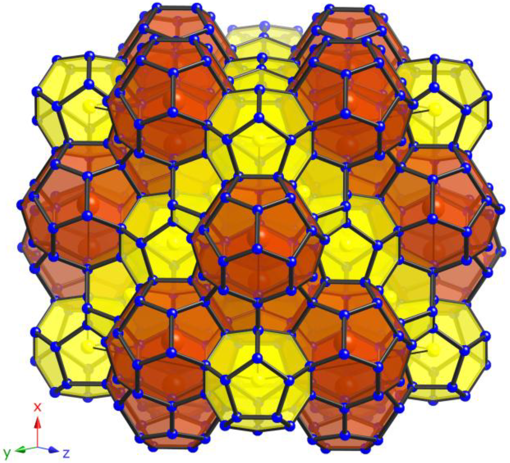
Figure 1.
View of the polyanionic framework of clathrates with type-II structure (yellow: pentagonal dodecahedra; red: hexakaidecahedra).
Figure 1.
View of the polyanionic framework of clathrates with type-II structure (yellow: pentagonal dodecahedra; red: hexakaidecahedra).
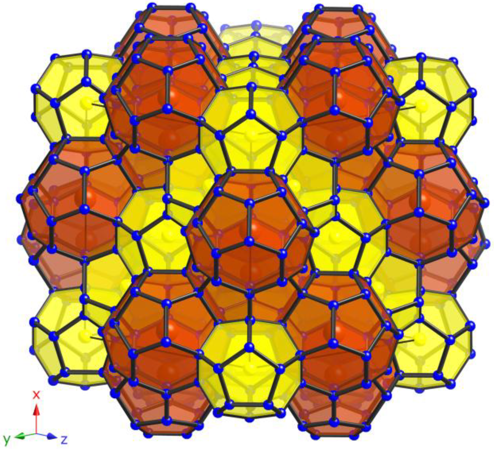

Table 2.
Atomic coordinates and equivalent isotropic displacement parameters (Ueq/Å2) for Cs8Na16Ga22.7Si113.3(1) (1); Rb8.4Na15.6(1)Ga19.6Si116.4(1) (2); and Rb8Na16Zn8.4Si127.6(1) (3). Coordinates are reported in the origin choice No. 2 for the cubic space group Fd3m.
| Atom | site | x/a | y/b | z/c | occupancy/% | Ueq [a] |
|---|---|---|---|---|---|---|
| Cs8Na16Ga22.7Si113.3(1) | ||||||
| Na | 16c | 0 | 0 | 0 | 100 | 0.0212(6) |
| Cs | 8b | 3/8 | 3/8 | 3/8 | 100 | 0.0205(2) |
| Si1/Ga1 | 96g | 0.06746(2) | x | 0.37069(3) | 78/22 [b] | 0.0087(2) |
| Si2/Ga2 | 32e | 0.21719(4) | x | x | 95.6/4.4(4) | 0.0079(4) |
| Si3/Ga3 | 8a | 1/8 | 1/8 | 1/8 | 96.8/3.3(7) | 0.0084(7) |
| Rb8.4Na15.6(1)Ga19.6Si116.4(1) | ||||||
| Na1/Rb1 | 16c | 0 | 0 | 0 | 97.9/2.1(7) | 0.020(1) |
| Rb2 | 8b | 3/8 | 3/8 | 3/8 | 100 | 0.0283(4) |
| Si1/Ga1 | 96g | 0.06734(3) | x | 0.37088(5) | 82/18 [b] | 0.0084(2) |
| Si2/Ga2 | 32e | 0.21728(6) | x | x | 93.9/6.1(5) | 0.0083(5) |
| Si3/Ga3 | 8a | 1/8 | 1/8 | 1/8 | 96/4(1) | 0.0078(9) |
| Rb8Na16Zn8.4Si127.6(1) | ||||||
| Na | 16c | 0 | 0 | 0 | 100 | 0.0212(10) |
| Rb | 8b | 3/8 | 3/8 | 3/8 | 100 | 0.0296(5) |
| Si1/Zn1 | 96g | 0.06740(4) | x | 0.37091(6) | 92/8 [b] | 0.0086(3) |
| Si2/Zn2 | 32e | 0.21755(7) | x | x | 97.6/2.4(6) | 0.0087(4) |
| Si3 | 8a | 1/8 | 1/8 | 1/8 | 100 | 0.0074(7) |
[a] Ueq is defined as one third of the trace of the orthogonalized Uij tensor; [b] As this is the largest contributor to error, the occupancy at the 96g site was refined freely first, and then fixed in order to minimize the estimated standard deviation in the chemical formulae.

Table 3.
Anisotropic displacement parameters (Uij/Å2) for Cs8Na16Ga22.7Si113.3(1) (1); Rb8.4Na15.6(1)Ga19.6Si116.4(1) (2); and Rb8Na16Zn8.4Si127.6(1) (3).
| Atom | U11 | U22 | U33 | U23 | U13 | U12 |
|---|---|---|---|---|---|---|
| Cs8Na16Ga22.7Si113.3(1) | ||||||
| Na | 0.0212(6) | =U11 | =U11 | –0.0031(6) | =U23 | =U23 |
| Cs | 0.0205(2) | =U11 | =U11 | 0 | 0 | 0 |
| Si1/Ga1 | 0.0086(2) | =U11 | 0.0091(3) | –0.0001(1) | =U23 | 0.0003(2) |
| Si2/Ga2 | 0.0079(4) | =U11 | =U11 | 0.0001(2) | =U23 | =U23 |
| Si3/Ga3 | 0.0084(7) | =U11 | =U11 | 0 | 0 | 0 |
| Rb8.4Na15.6(1)Ga19.6Si116.4(1) | ||||||
| Na1/Rb1 | 0.0233(7) | =U11 | =U11 | –0.0013(8) | =U23 | =U23 |
| Rb2 | 0.0299(4) | =U11 | =U11 | 0 | 0 | 0 |
| Si1/Ga1 | 0.0082(3) | =U11 | 0.0089(4) | –0.0003(2) | =U23 | 0.0002(3) |
| Si2/Ga2 | 0.0080(3) | =U11 | =U11 | 0.0007(3) | =U23 | =U23 |
| Si3/Ga3 | 0.0075(4) | =U11 | =U11 | 0 | 0 | 0 |
| Rb8Na16Zn8.4Si127.6(1) | ||||||
| Na | 0.0212(10) | =U11 | =U11 | –0.0025(10) | =U23 | =U23 |
| Rb | 0.0296(5) | =U11 | =U11 | 0 | 0 | 0 |
| Si1/Zn1 | 0.0083(4) | =U11 | 0.0093(5) | 0.0001(2) | =U23 | 0.0000(3) |
| Si2/Zn2 | 0.0087(4) | =U11 | =U11 | 0.0005(4) | =U23 | =U23 |
| Si3 | 0.0074(7) | =U11 | =U11 | 0 | 0 | 0 |

Table 4.
Selected interatomic distances for Cs8Na16Ga22.7Si113.3(1) (1); Rb8.4Na15.6(1)Ga19.6Si116.4(1) (2); and Rb8Na16Zn8.4Si127.6(1) (3). Tt denotes the mixed occupied Si/Ga and Si/Zn, respectively.
| Compound 1 | d/Å | Compound 2 | d/Å | Compound 3 | d/Å |
|---|---|---|---|---|---|
| Tt1–Tt1 (2×) | 2.4016(5) | Tt1–Tt1 (2×) | 2.3894(8) | Tt1–Tt1 (2×) | 2.377(1) |
| Tt1–Tt2 | 2.4067(5) | Tt1–Tt2 | 2.3989(8) | Tt1–Tt2 | 2.385(1) |
| Tt1–Tt1 | 2.430(1) | Tt1–Tt1 | 2.437(1) | Tt1–Tt1 | 2.412(2) |
| Tt2–Tt3 | 2.3847(9) | Tt2–Tt3 | 2.380(1) | Tt2–Si3 | 2.373(2) |
| Tt2–Tt1 (3×) | 2.4066(5) | Tt2–Tt1 (3×) | 2.3988(8) | Tt2–Tt1 (3×) | 2.385(1) |
| Tt3–Tt2 (4×) | 2.3847(9) | Tt3–Tt2 (4×) | 2.379(1) | Si3–Tt2 (4×) | 2.373(2) |
| Na–Tt3 (2×) | 3.2336(1) | Na1/Rb1–Tt3 (2×) | 3.2221(2) | Na–Si3 (2×) | 3.2049(2) |
| Na–Tt2 (6×) | 3.3140(4) | Na1/Rb1–Tt2 (6×) | 3.3066(6) | Na–Tt2 (6×) | 3.2912(7) |
| Na–Tt1 (12×) | 3.4260(3) | Na1/Rb1–Tt1 (12×) | 3.4102(5) | Na–Tt1 (12×) | 3.3939(6) |
| Cs–Tt1 (12×) | 3.9879(4) | Rb2–Tt1 (12×) | 3.9719(7) | Rb–Tt1 (12×) | 3.950(1) |
| Cs–Tt1 (12×) | 4.0657(5) | Rb2–Tt1 (12×) | 4.049(1) | Rb–Tt1 (12×) | 4.028(1) |
| Cs–Tt2 (4×) | 4.0825(9) | Rb2–Tt2 (4×) | 4.064(1) | Rb–Tt2 (4×) | 4.037(2) |
Due to the very different sizes of the two kinds of polyhedra, two very different guest atoms are required in order to achieve the complete and ordered occupation of the respective cages (see Figure 2). This warranted our choice of the pairs of alkali metals, namely Na/Cs and Na/Rb, respectively (rNa ≈ 1.57 Å, rRb ≈ 2.16 Å, rCs ≈ 2.35 Å [25]). The optimal sizes for an ordering are realized with Na for the smaller pentagon dodecahedra and Cs for the larger hexakaidecahedra in 1 and in Cs8Na16Ga21Si115 [17] and as well with Na again in the (Si,Zn)20 cages and Rb in the (Si,Zn)28 cages in compound 3. In contrast, the Ga-substituted framework of the Rb-containing clathrate 2 is intermediate in size (between 1 and 3), therefore, one can surmise that the larger cavities will still favor occupation by Rb atoms only, while the smaller ones are now large enough to host Na atoms, admixed with a small amount of Rb (refined as statistical ratio of Na:Rb = 97:3). For comparison, in Rb7.3Na16Ga20Si116 [17], the pentagonal dodecahedra are fully occupied by Na, while the hexakaidecahedra are only 90% occupied by the Rb guest atoms, despite the similar amount of Ga substituting for Si in the framework and the correspondingly similar sizes of the (Ga,Si)20 pentagonal dodecahedra and the (Ga,Si)28 hexakaidecahedra (between Rb7.3Na16Ga20Si116 [17] and structure 2). We were intrigued by this difference in the filling patterns for Rb8.4Na15.6(1)Ga19.6Si116.4(1) and the previously reported Rb7.3Na16Ga20Si116 [17]. We speculated that differences in the reaction conditions might explain why this happens, and attempted to synthesize a new clathrate type-II from Rb, Na, Ga, and Si, using a modified synthetic procedure. Several random crystals selected from this reaction were subjected to crystallographic analysis and showed again the exact same phenomenology—one crystal was indexed with a unit cell a = 14.8722(5) Å, and another one with a = 14.8765(5) Å, both at 200 K. Despite these values being within a few standard deviations from each other, structure refinements showed the former to be an analog of 2, i.e., the structure with the small Na-Rb disorder within the pentagonal dodecahedra, while the latter turned out to be analogous to the previously reported Rb–Na–Ga–Si phase with underoccupied hexakaidecahedral cages. The slight decrease in the unit cell parameters for these two structures compared to Rb8.4Na15.6(1)Ga19.6Si116.4(1) and Rb7.3Na16Ga20Si116 is apparently due to the slight difference in the Ga content (an artifact of the change in the synthesis scheme). Based on the above, it is evident that the Rb–Na–Ga–Si system requires more detailed studies to fully understand this behavior, which is not mirrored by the analogous Cs–Na–Ga–Si system.
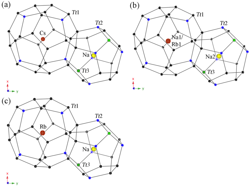
Figure 2.
Representation of the polyhedral cages in type-II structures with anisotropic displacement parameters, drawn at the 95% probability level. Cs8Na16Ga22.7Si113.3(1) (a); Rb8.4Na15.6(1)Ga19.6Si116.4(1) (b); and Rb8Na16Zn8.4Si127.6(1) (c).
Figure 2.
Representation of the polyhedral cages in type-II structures with anisotropic displacement parameters, drawn at the 95% probability level. Cs8Na16Ga22.7Si113.3(1) (a); Rb8.4Na15.6(1)Ga19.6Si116.4(1) (b); and Rb8Na16Zn8.4Si127.6(1) (c).
The interatomic distances between the filler atoms and the framework are within the intervals of dNa–Si/Ga = 3.234(1) to 3.420(1) Å and dCs–Si/Ga = 3.988(1) to 4.083(1) Å for 1, dNa1/Rb1–Si/Ga = 3.222(1) to 3.410(1) Å and dRb2–Si/Ga = 3.972(1) to 4.064(1) Å for 2, and dNa–Si/Ga = 3.205(1) to 3.392(1) Å and dRb–Si/Ga = 3.950(1) to 4.037(1) Å for 3, respectively (see Table 4). The distances for Cs8Na16Ga21Si115 (dNa–Si/Ga = 3.230(1)–3.416(1) Å and dCs–Si/Ga = 3.984(1)–4.077(2) Å) and Rb7.3Na16Ga20Si116 (dNa–Si/Ga = 3.222(1)–3.411(1) Å and dRb–Si/Ga = 3.971(1)–4.066(2) Å) [17] are very close in values as well. According to the Zintl-Klemm rules [26,27], the formulae for charge balanced compounds are [(Cs or Rb)+]8[Na+]16[4b-Ga1−]24[4b-Si0]112 for 1 and 2 and [Rb+]8[Na+]16[4b-Zn2−]12[4b-Si0]124 for 3. Hence, the composition of the Cs-containing compound 1 is the closest to the ideal formula, and a semiconducting-like (heavily doped, or even poorly metallic) behavior can be expected, while these for both Rb-containing clathrates 2 and 3 are obviously not charge-balanced and a metallic behavior can be predicted for both phases. In support of this reasoning, we can cite the known germanium clathrates Cs8Na16Ag6.7Ge129.3 [18] and Cs8Na16Cu5Ge131 [19], whose formulae also deviate from the ideal, charge-balanced compositions.
2.3. Crystal Chemistry of the Type-I Clathrates
Like for the above reported type-II clathrates, the cell parameters for the individual type-I clathrates are also decreasing at 200 K with a = 10.4710(2) Å for Cs6Na2Ga8.25Si37.75(3) (4), to a = 10.4466(4) for Rb6.34Na1.66(2)Ga8.02Si37.98(3) (5), to a = 10.3543(4) Å for Rb5.20Na2.80(4)Zn3.85Si42.15(2) (6) corresponding to the amount of Ga or Zn in the Si-based framework and the used alkali metals as guest atoms (see Table 5, Table 6 and Table 7). The insertion of Na in Rb6.34Na1.66(2)Ga8.02Si37.98(3) has very little influence on the unit cell, as evident by comparing it to that of the ternary compound Rb8Ga8Si38 (a = 10.469(2) Å at room temperature) [11], while the cell parameter for the Zn-containing clathrate is even significantly smaller than that of K8Ga7.9Si38.1 (a = 10.427(1) Å at room temperature) [10].

Table 5.
Selected crystal data and structure refinement parameters for Cs6Na2Ga8.25Si37.75(3) (4); Rb6.34Na1.66(2)Ga8.02Si37.98(3) (5); and Rb5.20Na2.80(4)Zn3.85Si42.15(2) (6).
| 4 | 5 |
|---|---|
| 2479.03 | 2205.85 |
| 10.4710(2) | 10.4466(4) |
| 1148.06(4) | 1140.05(8) |
| 3.59 | 3.21 |
| 10.48 | 12.42 |
| 0.053 | 0.089 |
| 241/0/18 | 241/0/20 |
| 0.0159 | 0.0167 |
| 0.0394 | 0.0362 |
| 1.202 | 1.072 |
| 0.59 & −0.42 | 0.37 & −0.30 |
[a] R1 = ∑||Fo| – |Fc||/∑|Fo|; wR2 = [∑[w(Fo2 – Fc2)2]/∑[w(Fo2)2]]1/2, where w = 1/[σ2Fo2 + (A·P)2 + (B·P)], and P = (Fo2 + 2Fc2)/3; A and B weight coefficients.

Table 6.
Atomic coordinates and equivalent isotropic displacement parameters (Ueq/Å2) for Cs6Na2Ga8.25Si37.75(3) (4), Rb6.34Na1.66(2)Ga8.02Si37.98(3) (5), and Rb5.20Na2.80(4)Zn3.85Si42.15(2) (6).
| Atom | Site | x/a | y/b | z/c | occupancy/% | Ueq(a) |
|---|---|---|---|---|---|---|
| Cs6Na2Ga8.25Si37.75(3) | ||||||
| Cs | 6d | 1/4 | 1/2 | 0 | 100 | 0.0131(2) |
| Na | 2a | 0 | 0 | 0 | 100 | 0.0176(13) |
| Si1/Ga1 | 24k | 0 | 0.30307(8) | 0.11830(8) | 86(1)/14(1) | 0.0069(2) |
| Si2/Ga2 | 16i | 0.18385(7) | x | x | 96(1)/4(1) | 0.0076(3) |
| Si3/Ga3 | 6c | 1/4 | 0 | 1/2 | 30(1)/70(1) | 0.0079(4) |
| Rb6.34Na1.66(2)Ga8.02Si37.98(3) | ||||||
| Rb1 | 6d | 1/4 | 1/2 | 0 | 100 | 0.0159(2) |
| Na2/Rb2 | 2a | 0 | 0 | 0 | 83(1)/17(1) | 0.0120(6) |
| Si1/Ga1 | 24k | 0 | 0.30439(7) | 0.11798(7) | 85(1)/15(1) | 0.0079(2) |
| Si2/Ga2 | 16i | 0.18411(5) | x | x | 97(1)/3(1) | 0.0078(3) |
| Si3/Ga3 | 6c | 1/4 | 0 | 1/2 | 34(1)/66(1) | 0.0076(2) |
| Rb5.20Na2.80(4)Zn3.85Si42.15(2) | ||||||
| Rb1/Na1 | 6d | 1/4 | 1/2 | 0 | 86(1)/14(1) | 0.0161(2) |
| Na2 | 2a | 0 | 0 | 0 | 100 | 0.0124(7) |
| Si1/Zn1 | 24k | 0 | 0.30472(6) | 0.11742(6) | 97(1)/3(1) | 0.0071(2) |
| Si2/Zn2 | 16i | 0.18363(4) | x | x | 98(1)/2(1) | 0.0067(3) |
| Si3/Zn3 | 6c | 1/4 | 0 | 1/2 | 54(1)/46(1) | 0.0074(2) |
[a] Ueq is defined as one third of the trace of the orthogonalized Uij tensor.

Table 7.
Anisotropic displacement parameters (Uij/Å2) for Cs6Na2Ga8.25Si37.75(3) (4); Rb6.34Na1.66(2)Ga8.02Si37.98(3) (5); and Rb5.20Na2.80(4)Zn3.85Si42.15(2) (6).
| Atom | U11 | U22 | U33 | U23 | U13 | U12 |
|---|---|---|---|---|---|---|
| Cs6Na2Ga8.25Si37.75(3) | ||||||
| Cs | 0.0098(3) | 0.0147(2) | =U22 | 0 | 0 | 0 |
| Na | 0.0176(13) | =U11 | =U11 | 0 | 0 | 0 |
| Si1/Ga1 | 0.0060(4) | 0.0071(4) | 0.0077(4) | 0.0004(3) | 0 | 0 |
| Si2/Ga2 | 0.0076(3) | =U11 | =U11 | –0.0002(3) | =U23 | =U23 |
| Si3/Ga3 | 0.0080(5) | 0.0079(4) | =U22 | 0 | 0 | 0 |
| Rb6.34Na1.66(2)Ga8.02Si37.98(3) | ||||||
| Rb | 0.0116(4) | 0.0181(3) | =U22 | 0 | 0 | 0 |
| Na/Rb1 | 0.0120(6) | =U11 | =U11 | 0 | 0 | 0 |
| Si1/Ga1 | 0.0077(4) | 0.0082(4) | 0.0077(4) | 0.0006(3) | 0 | 0 |
| Si2/Ga2 | 0.0078(3) | =U11 | =U11 | 0.0000(2) | =U23 | =U23 |
| Si3/Ga3 | 0.0080(5) | 0.0074(3) | =U22 | 0 | 0 | 0 |
| Rb5.20Na2.80(4)Zn3.85Si42.15(2) | ||||||
| Rb1/Na1 | 0.0124(3) | 0.0179(3) | =U22 | 0 | 0 | 0 |
| Na2 | 0.0124(7) | =U11 | =U11 | 0 | 0 | 0 |
| Si1/Zn1 | 0.0065(4) | 0.0077(4) | 0.0069(3) | 0.0004(3) | 0 | 0 |
| Si2/Zn2 | 0.0067(3) | =U11 | =U11 | –0.0001(2) | =U23 | =U23 |
| Si3/Zn3 | 0.0081(4) | 0.0070(3) | =U22 | 0 | 0 | 0 |
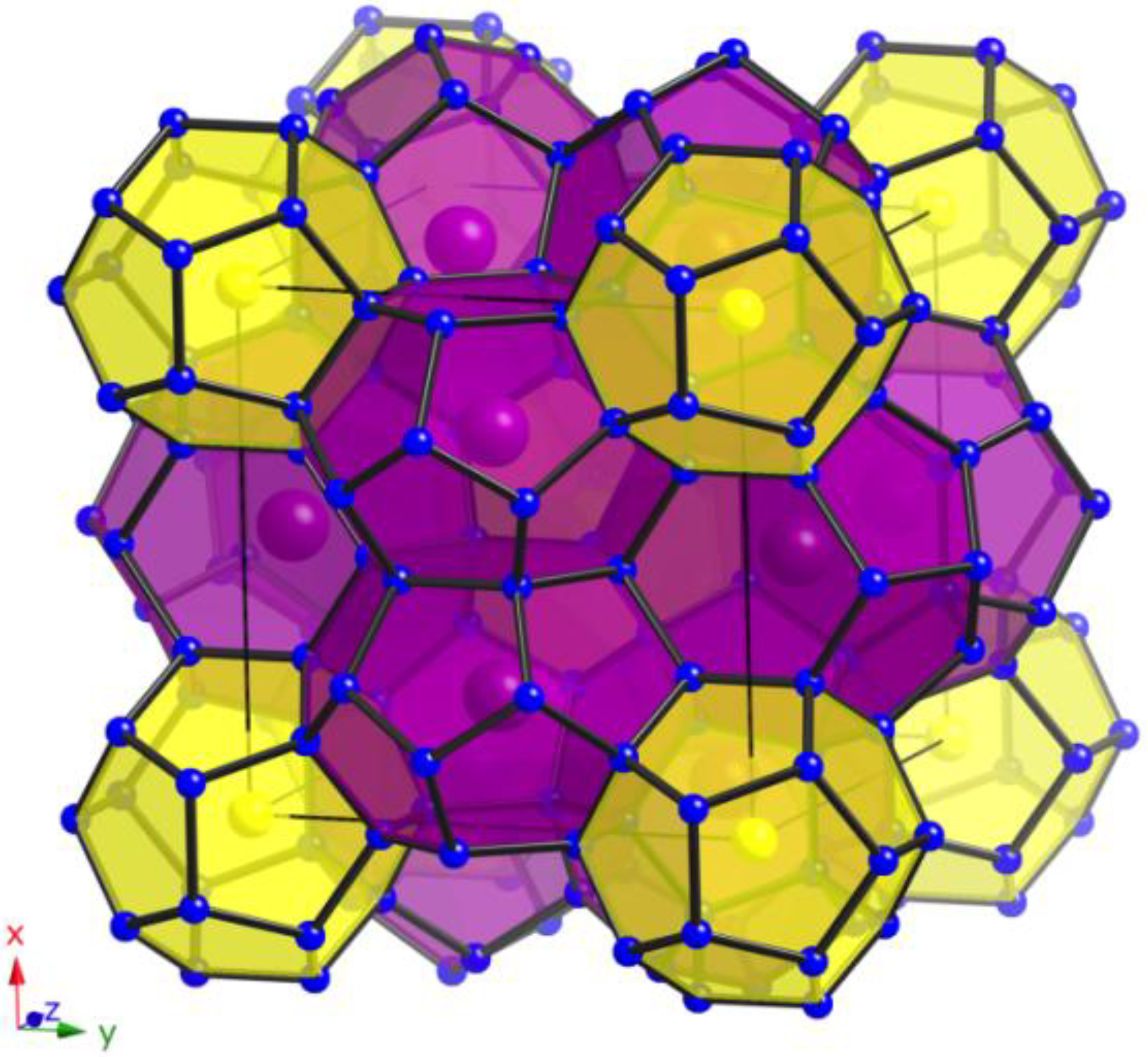
In the cubic type-I structure (Pm3n) of these clathrates, statistically disordered Si and M atoms (M = Ga, Zn) form the open-framework with 46 tetrahedrally coordinated atoms per unit cell located on the Wyckoff sites 24k, 16i, and 6c. Overall, one unit cell encompasses two (Si,M)20 pentagonal dodecahedra and six (Si,M)24 tetrakaidecahedra (see Figure 3) creating a space-filling network. The 24-atom polyhedra share their two hexagonal faces to create three perpendicular, but not interpenetrating columns running along [100], [010], and [001] of the cube. These columns encapsulate the isolated 20-atom polyhedra in the created voids. The M atoms substitute all three framework sites in every clathrate (Table 6) with an apparent preference to occupy site 6c. The ratios are in agreement with the literature, whereby the preference for the 6c site is confirmed. Our data show the following ratios—Si:Ga = 86:14 on 24k, 96:4 on 16i and 30:70 on 6c for 4 and Si:Ga = 85:15 on 24k, 97:3 on 16i and 34:66 on 6c for 5 similar and comparable to these of the ternary clathrates K8Ga7.9Si38.1 (Si amounts in percents of the site occupation factors: 83%, 98%, and 43%, respectively) [10] and Rb8Ga8Si38 (Si amounts in percents of the site occupation factors: 78%, 99%, and 59%, respectively) [11], while the ratio of Si:Zn = 97:3 on 24k, 98:2 on 16i, and 54:46 on 6c for 6 follow the reduced amount of Zn.
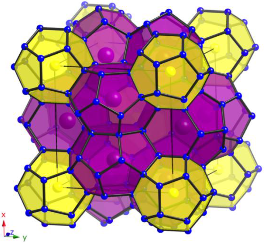
Figure 3.
View of the polyanionic framework of clathrates with type-I structure (yellow: pentagonal dodecahedra; purple: tetrakaidecahedra).
Figure 3.
View of the polyanionic framework of clathrates with type-I structure (yellow: pentagonal dodecahedra; purple: tetrakaidecahedra).
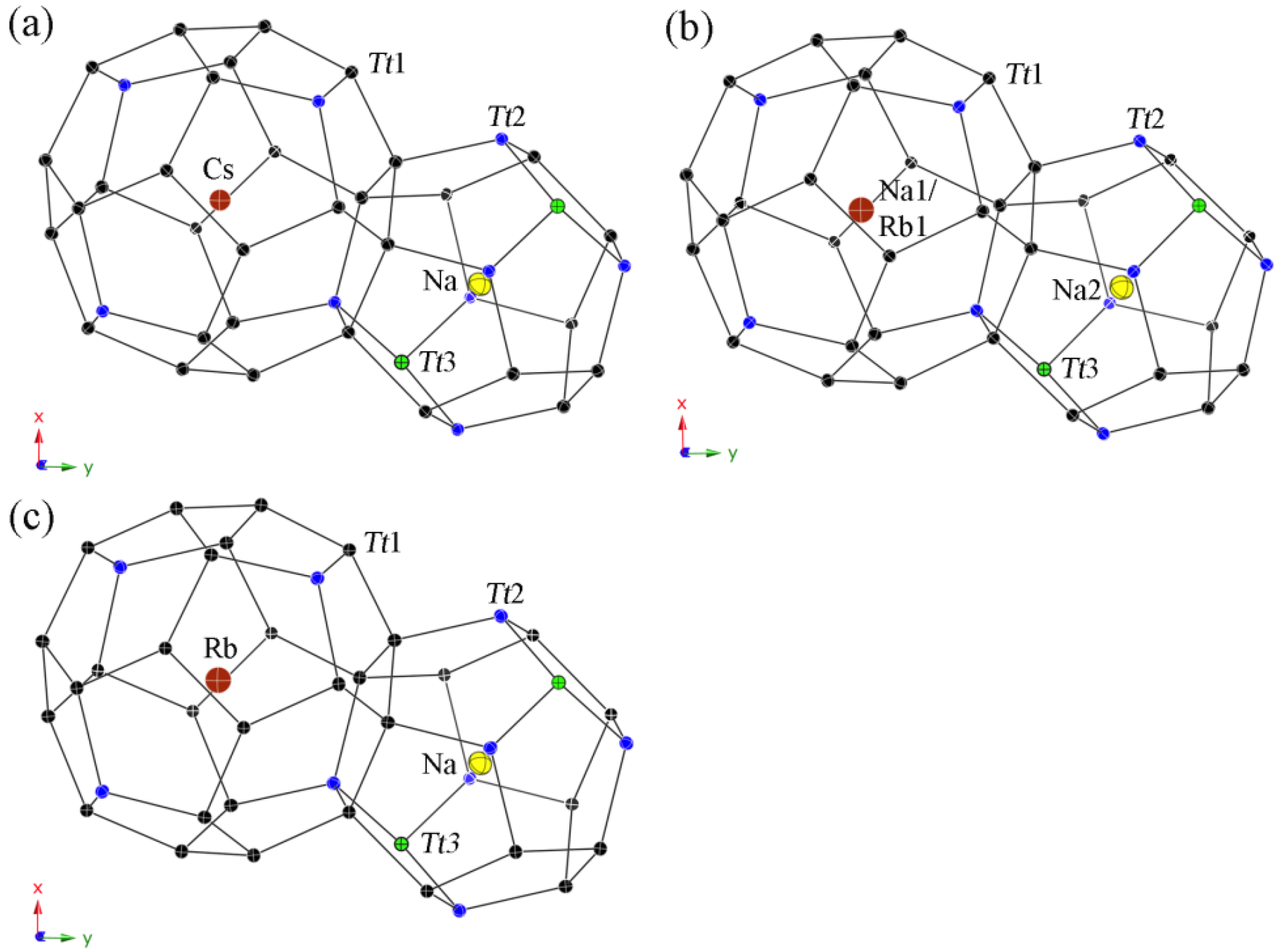
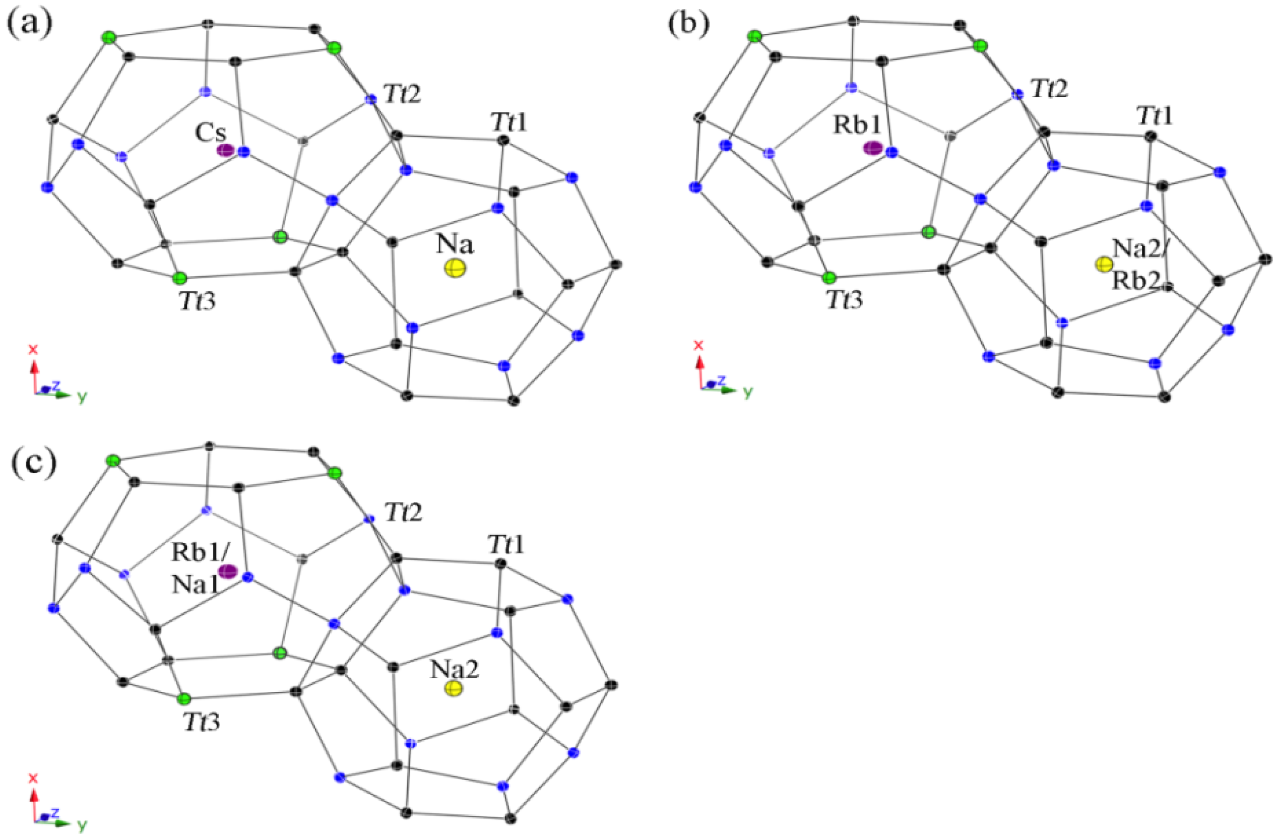
All guest atoms are located in the center of the polyhedra with usual anisotropic displacement parameters (see Figure 4). Both kinds of cavities are closer in size than for the type-II clathrates, yet, a strict ordering occurs again in the Cs-containing clathrate 4 with only Na atoms in the pentagon dodecahedra on site 2a and Cs atoms in the tetrakaidecahedra on site 6d. In contrast, the polyhedra sizes are not so unambiguous for both Rb-containing clathrates. Hence, the (Si,Ga)20 cavities in 5 are large enough for the Rb cations and a statistical mixed occupancies occurs with a ratio of Na2:Rb2 = 83:17, while only Rb cations are in the (Si,Ga)24 cavities. In the Zn-containing clathrate 6, the tetrakaidecahedra are already too small to encapsulate only Rb cations, resulting in a mixed occupancy of Rb1:Na1 with the ratio 86:14, and the pentagon dodecahedra are filled completely with Na atoms.
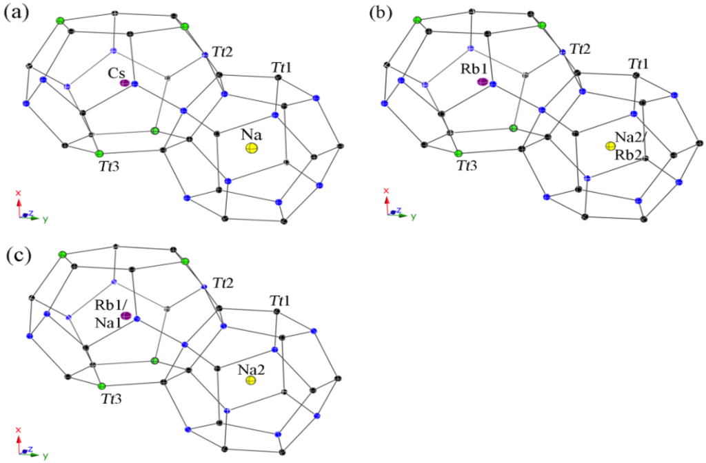
Figure 4.
Representation of the polyhedral cages in the type-I structures with anisotropic displacement parameters, drawn at the 95% probability level. (a) Cs6Na2Ga8.25Si37.75(3); (b) Rb6.34Na1.66(2)Ga8.02Si37.98(3); and (c) Rb5.20Na2.80(4)Zn3.85Si42.15(2).
Figure 4.
Representation of the polyhedral cages in the type-I structures with anisotropic displacement parameters, drawn at the 95% probability level. (a) Cs6Na2Ga8.25Si37.75(3); (b) Rb6.34Na1.66(2)Ga8.02Si37.98(3); and (c) Rb5.20Na2.80(4)Zn3.85Si42.15(2).
The dependence of content and size of the framework building atoms is once more visible in the decreasing intervals for the distances (see Table 8) with dSi/Ga–Si/Ga = 2.395(1)–2.481(1) Å, dNa–Si/Ga = 3.334(1)–3.407(1) Å, dCs–Si/Ga = 3.555(1)–4.035(1) Å for 4, dSi/Ga–Si/Ga = 2.384(2)–2.465(1) Å, dNa2/Rb2–Si/Ga = 3.331(1)–3.410(1) Å, dRb1–Si/Ga = 3.538(1)–4.031(1) Å for 5, and dSi/Ga–Si/Ga = 2.378(1)–2.444(1) Å, dNa2–Si/Ga = 3.293(1)–3.381(1) Å, dRb1/Na1–Si/Ga = 3.503(1)–4.002(1) Å for 6 as well as for the ternary clathrates Rb8Ga8Si38 (dSi/Ga–Si/Ga = 2.365(1)–2.494(1) Å dRb2–Si/Ga = 3.351(1)–3.437(1) Å dRb1–Si/Ga = 3.540(1)–4.030(1) Å) [11] and K8Ga7.9Si38.1 (dSi/Ga–Si/Ga = 2.366(1)–2.463(1) Å dK2–Si/Ga = 3.332(1)–3.418(1) Å dK1–Si/Ga = 3.523(1)–4.025(1) Å) [10] and in good agreement with the bond lengths of the corresponding type-II clathrates (vide supra).

Table 8.
Selected interatomic distances for Cs6Na2Ga8.25Si37.75(3) (4); Rb6.34Na1.66(2)Ga8.02Si37.98(3) (5); and Rb5.20Na2.80(4)Zn3.85Si42.15(2) (6). Tt denotes the mixed occupied Si/Ga and Si/Zn, respectively.
| Compound 4 | d/Å | Compound 5 | d/Å | Compound 6 | d/Å |
|---|---|---|---|---|---|
| Tt1–Tt2 (2×) | 2.3949(6) | Tt1–Tt2 (2×) | 2.3991(5) | Tt1–Tt2 (2×) | 2.3784(4) |
| Tt1–Tt1 | 2.478(2) | Tt1–Tt1 | 2.465(1) | Tt1–Tt1 | 2.432(1) |
| Tt1–Tt3 | 2.4807(8) | Tt1–Tt3 | 2.4653(7) | Tt1–Tt3 | 2.4440(6) |
| Tt2–Tt2 | 2.3949(6) | Tt2–Tt2 | 2.384(2) | Tt2–Tt2 | 2.3784(4) |
| Tt2–Tt1 (3×) | 2.399(2) | Tt2–Tt1 (3×) | 2.3991(5) | Tt2–Tt1 (3×) | 2.381(2) |
| Tt3–Tt1 (4×) | 2.4807(8) | Tt3–Tt1 (4×) | 2.4654(7) | Tt3–Tt1 (4×) | 2.4440(6) |
| Cs–Tt1 (8×) | 3.5552(5) | Rb1–Tt1 (8×) | 3.5377(5) | Rb1/Na1–Tt1 (8×) | 3.5025(4) |
| Cs–Tt2 (8×) | 3.8916(4) | Rb1–Tt2 (8×) | 3.8811(3) | Rb1/Na1–Tt2 (8×) | 3.8465(3) |
| Cs–Tt3 (4×) | 3.702(1) | Rb1–Tt3 (4×) | 3.6934(1) | Rb1/Na1–Tt3 (4×) | 3.6608(1) |
| Cs–Tt1 (4×) | 4.0352(8) | Rb1–Tt1 (4×) | 4.031(1) | Rb1/Na1–Tt1 (4×) | 4.002(1) |
| Na–Tt2 (8×) | 3.334(1) | Na2/Rb2–Tt2 (8×) | 3.331(1) | Na–Tt2 (8×) | 3.2932(7) |
| Na–Tt1 (12×) | 3.4066(8) | Na2/Rb2–Tt1 (12×) | 3.4103(7) | Na–Tt1 (12×) | 3.3813(6) |
The refined formulae for the type-I clathrates are satisfying the Zintl-Klemm ideas for valence electrons counting and charge balance with [(Na,Cs or Rb)+]8[4b-Ga1−]8[4b-Si0]38 for Cs6Na2Ga8.25Si37.75(3) and Rb6.34Na1.66(2)Ga8.02Si37.98(3), and [(Na,Rb)+]8[4b-Zn2−]4[4b-Si0]42 for Rb5.20Na2.80(4)Zn3.85Si42.15(2), hence, semiconducting behavior can be expected for all three compounds. Given this and the robust open framework with many possibilities for substitutions, such compounds could be candidate-materials for thermoelectric applications. However, these speculations could not be confirmed as part of this study, as the synthesis requirements for phase-pure sample have not been yet worked out.
3. Experimental Section
3.1. Synthesis
Due to the high reactivity of the alkali metals in air, all manipulations involving elemental Na, Rb, and Cs were carried out in a glove box with O2/H2O level below 1 ppm or under vacuum. All chemicals were purchased from Alfa or Sigma-Aldrich with purity higher than 99.9%.wt. In order to carry out the reactions in a safe and reliable manner, the elements were loaded in a ratio of Na:A:M:Si = 2:1:3:14 (A = Rb, Cs; M = Ga, Zn) in Nb tubes (4.5 cm long, diameter 1 cm). After arc sealing and enclosing of the tubes in evacuated, fused silica jackets, the samples were heated slowly in programmable muffle furnaces to 950 °C with a rate of 10 °C/h, annealed for 15 h, and then cooled down (rate −150 °C/h) to 650 °C, dwelled for 4 d, and cooled down (rate −5 °C/h) to room temperature. The obtained type-I and type-II clathrates are stable in air and moisture for a couple of months. Leftover Si can be washed out with 1 M NaOH-solution.
In all systems, variations of the loading ratio for the idealized formulae (type-I and type-II) as well as of the temperature profiles (reaction temperatures varied between 600 and 950 °C) resulted only in small changes of the ratios of the clathrate types and leftover Si. The same three-phase product occurs (i) if the reactions (stoichiometric loadings in Nb tubes) are performed with induction heating at temperatures between 800 and 900 °C for 10 min or (ii) if the flux method is used. For the latter one, a ten-fold excess of Ga or Zn, respectively, were used as flux. The samples were loaded in Nb tubes (8 cm long, diameter 1 cm, and an Nb sheet with drilled hollows is inserted as filter part), enclosed in evacuated silica tubes, heated to 800 °C (rate 100 °C/h), annealed for 2 h and then cooled down with a rate of −2 °C/h. Subsequently, the flux was removed at 300 °C.
Analogous reactions in the system Cs–Na–Zn–Si may have produced the type-II clathrate Cs8Na16ZnxSi136–x, but this supposition from powder X-ray diffraction data is not yet confirmed from structure refinements by single-crystal work. The major products of the reaction appear to be NaZn13 and unreacted Si. There is no experimental evidence suggesting that type-I compound can be obtained in this system. More work is required and future results will be published elsewhere.
Independent from the type of synthesis method employed, the obtained single-crystals were small and normally intergrown together. The crystals were cuboidal in shape with dark-to-black appearance. Both type-I and type-II had the same morphology and could not be distinguished under a microscope. The typical size of the single-crystals was below 0.1 × 0.1 × 0.1 mm, and, therefore, property measurements on individual crystallites also could not be carried out.
3.2. Single Crystal X-ray Diffraction
Single-crystal X-ray diffraction data were collected on a Bruker Smart Apex diffractometer at 200 K using graphite-monochromated Mo-Kα radiation (α = 0.71073 Å). Suitable single crystals of each compound were selected and cut to smaller dimensions (less than 0.1 mm) under mineral oil. The SMART [28] and SAINTplus [29] programs were used for the data collection, integration and the global unit cell refinement from all data. Semi-empirical absorption correction was applied with SADABS [30]. The structures were refined to convergence by full matrix least-square methods on F2, as implemented in SHELXTL [31]. All sites were refined with anisotropic displacement parameters. The atomic parameters were standardized with StructureTidy as implemented in Platon [32].
The contrast between the X-ray atomic scattering factors between Zn, Ga and Si, respectively, is significant enough to allow precise refinements of the site occupation factors. In all cases, the occupancies of the framework sites were first freely refined (individually, while the remaining ones were kept fixed). For the type-II structures, the occupancies of all three Si/M (M = Ga, Zn) showed mixed occupation, except for Rb8Na16Zn8.4Si127.6(1), where Zn was found only on framework sites 96g and 32e. Notably, the largest amount of Ga or Zn was found at the site with the lowest symmetry index (96g), while the completely opposite observations can be made for the type-I structures—in these cases, all three framework sites are co-occupied, with a noted preference for the site with the highest symmetry (6c). In all three type-I clathrates, small amounts of Ga and Zn, respectively, co-occupy framework sites 16i and 24k as well. This situation is similar to Ba8Zn7Si39 [33], in which sites 6c (77% Zn, 23% Si) and 24k (9% Zn, 91% Si) are mixed occupied. In the Ba8ZnxGe46–x–yy compounds with 2.1 ≤ x ≤ 7.7 [34], the Zn atoms are suggested not to occupy the other site(s) until site 6c is completely filled by Zn. Such assertion pertaining to low framework substitution levels is interesting and warrants further exploration, however, the refinements of Zn/Ge may not be as accurate as Zn/Si due to the better contrast in their X-ray scattering factors.
The individual ratios of the statistical mixed order are compiled in Table 2 and Table 6. Hints for vacancies in the framework (e.g., low occupation factors, elongated displacement parameters of atoms neighboring possible vacant sites, etc.) are not observed for any compound. The guest atoms are always located in the center of the respective cavities (16c and 8b for type-II, and 6d and 2a for type-I, respectively) and the values for the anisotropic displacement parameters do not indicate any kind of off-centering.
Selected details of the data collections and structure refinement parameters are listed in Table 1 and Table 5. The atomic coordinates and equivalent isotropic displacement parameters are compiled in Table 2 and Table 6. The anisotropic displacement parameters can be found in Table 3 and Table 7 and selected interatomic distances are summarized in Table 4 and Table 8. Additional details of the crystal structure analyses may be requested from the Fachinformationszentrum Karlsruhe, D-76344 Eggenstein-Leopoldshafen, Germany (Fax: +49-7247-808-666, E-Mail: crysdata@fiz-karlsruhe.de) on quoting the depository numbers CSD-427236 for Cs8Na16Ga22.7Si113.3(1), CSD-427237 for Rb8.4Na15.6(1)Ga19.6Si116.4(1), CSD-427238 for Rb8Na16Zn8.4Si127.6(1), CSD-427239 for Cs6Na2Ga8.25Si37.75(3), CSD-427240 for Rb6.34Na1.66(2)Ga8.02Si37.98(3), and CSD-427241 for Rb5.20Na2.80(4)Zn3.85Si42.15(2), respectively.
3.3. Powder X-ray Diffraction
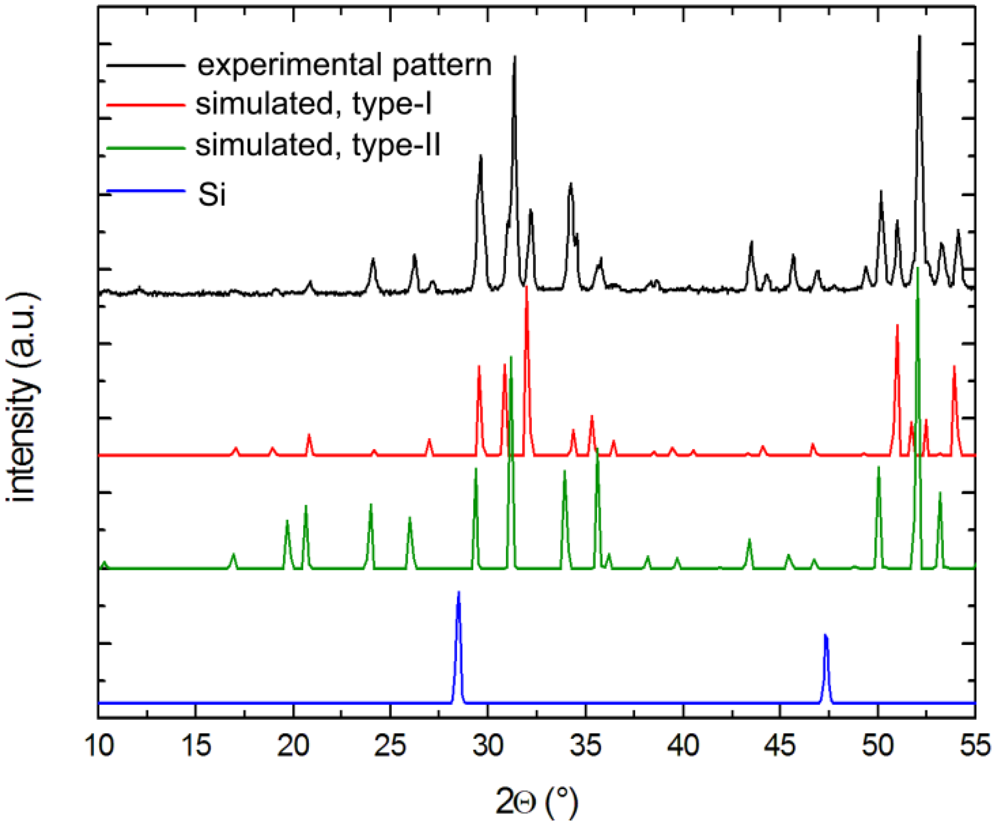
X-ray powder diffraction patterns of selected crystals were carried out at room temperature on a Rigaku MiniFlex powder diffractometer using Cu-Kα radiation. Typical runs included θ–θ scans (2θmax = 65°) with the scan steps of 0.05° and 2 s/step counting time. The data were analyzed with the JADE 6.5 software package [35]. The intensities and the positions of the experimentally observed peaks and those calculated based on the corresponding single-crystal structures matched very well with one another (see Figure 5).
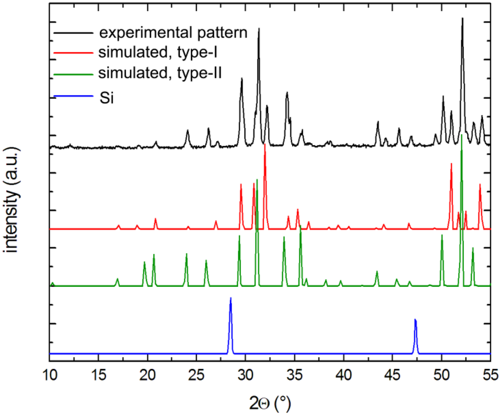
Figure 5.
Representative powder x-ray pattern of a Cs-containing sample after soaking in 1 M NaOH solution. Both clathrates types are detected, while Si is dissolved completely.
Figure 5.
Representative powder x-ray pattern of a Cs-containing sample after soaking in 1 M NaOH solution. Both clathrates types are detected, while Si is dissolved completely.
3.4. EDX Analysis
Multiple crystals for each composition were also determined by means of energy dispersive X-ray spectroscopy (EDX) on a JEOL 7400F electron microscope equipped with an INCA-OXFORD energy-dispersive spectrometer. All four elements could be detected in ratios consistent with the refined compositions, however precise quantitative analyses were hampered due to the strong overlay of the lines for Si/Rb and Na/Ga or Na/Zn, respectively.
4. Conclusions
In all three studied systems: Cs–Na–Ga–Si, Rb–Na–Ga–Si, and Rb–Na–Zn–Si, the synthesis of type-I and type-II clathrates is proved possible. However, the respective clathrate phases are always co-crystallizing in the same sample batches, irrespective of the tried different synthesis routes (stoichiometric reactions with long-time annealing in muffle furnaces or with short-time heating in induction furnaces as well as flux reactions). As mechanical separation was not achievable either, measurements of the transport properties could not be performed. Another problem that calls for further investigation is the mixed occupancies of the cavities in the Rb-containing clathrates. A control over the composition seems only be possible for the Cs clathrates due to the strict filling of the cavities and, therefore, resulting in nearly line compounds. Thus, this system can prove the most promising if the synthetic problems leading to impurity phases can be resolved in further investigations.
Acknowledgments
The authors gratefully acknowledge financial support from the US Department of Energy through grants DE-SC0001360 and DE-SC0008885.
Conflicts of Interest
The authors declare no conflict of interest.
References and Notes
- Jeffrey, G.A. Hydrate Inclusion Compounds. In Inclusion Compounds; Atwood, I.J.L., Davies, J.E.D., MacNicol, D.D., Eds.; Academic Press: London, UK, 1984; pp. 135–190. [Google Scholar]
- Slack, G.A. New Materials and Performance Limits for Thermoelectric Cooling. In CRC Handbook of Thermoelectrics; Rowe, D.M., Ed.; CRC Press: Boca Raton, FL, USA, 1995; pp. 407–440. [Google Scholar]
- Nolas, G.S.; Cohn, J.L.; Slack, G.A.; Schjuman, S.B. Semiconducting Ge clathrates: Promising candidates for thermoelectric applications. Appl. Phys. Lett. 1998, 73, 178–180. [Google Scholar] [CrossRef]
- Sales, B.C.; Chakoumakos, B.C.; Mandrus, D.; Sharp, J.W. Atomic displacement parameters and the lattice thermal conductivity of clathrate-like thermoelectric compounds. J. Solid State Chem. 1999, 146, 528–532. [Google Scholar] [CrossRef]
- Christensen, M.; Johnson, S.; Iversen, B.B. Thermoelectric clathrates of type-I. Dalton Trans. 2010, 39, 978–992. [Google Scholar] [CrossRef]
- Bobev, S.; Sevov, S.C. Clathrates of group 14 with alkali metals: An exploration. J. Solid State Chem. 2000, 153, 92–105. [Google Scholar] [CrossRef]
- Beekman, M.; Nolas, G.S. Inorganic clathrate-II materials of group 14: Synthesic routes and physical properties. J. Mater Chem. 2008, 18, 842–851. [Google Scholar] [CrossRef]
- Shevelkov, A.V.; Kovnir, K. Zintl Clathrates. In Structure and Bonding; Springer: Berlin, Germany, 2011; Volume 990, pp. 97–142. [Google Scholar]
- Prokofiev, A.; Sidorenko, A.; Hradil, K.; Ikeda, M.; Svagera, R.; Waas, M.; Winkler, H.; Neumaier, K.; Paschen, S. Thermopower enhancement by encapsulating cerium in clathrate cages. Nature Mater. 2013, 12, 1096–1101. [Google Scholar] [CrossRef]
- Kröner, R.; Peters, K.; von Schnering, H.G.; Nesper, R. Crystal structure of the clathrates K8Ga8Si38 and K8Ga8Sn38. Z. Kristallogr. 1998, 231, 667–668. [Google Scholar]
- Von Schnering, H.G.; Kröner, R.; Menke, H.; Peters, K.; Nesper, R. Crystal structure of the clathrates Rb8Ga8Sn38, Rb8Ga8Ge38 and Rb8Ga8Si38. Z. Kristallogr. 1998, 213, 677–678. [Google Scholar]
- Paschen, S.; Budnyk, S.; Köhler, U.; Prots, Y.; Hiebl, K.; Steglich, F.; Grin, Y. New type-I clathrates with ordered Eu distribution. Physica B 2006, 383, 89–92. [Google Scholar] [CrossRef]
- Von Schnering, H.G.; Menke, H.; Kröner, R.; Peters, E.M.; Peters, K.; Nesper, R. Crystal structure of the clathrates Rb8In8Ge38 and K8In8Ge38. Z. Kristallogr. 1998, 213, 673–374. [Google Scholar]
- Schäfer, M.C.; Bobev, S. On the possibility for Rb- and Eu-cation ordering in type-I clathrates. Synthesis and homogeneity range of the novel compounds Rb8–xEux(In,Ge)46 (0.6 ≤ x ≤ 1.8). Acta Crystallogr. 2013, C69, 1457–1461. [Google Scholar]
- Bobev, S.; Sevov, S.C. Synthesis and characterization of stable stoichiometric clathrates of silicon and germanium: Cs8Na16Si136 and Cs8Na16Ge136. J. Am. Chem. Soc. 1999, 121, 3795–3796. [Google Scholar] [CrossRef]
- Nolas, G.S.; Vanderveer, D.G.; Wilkinson, A.P.; Cohn, J.L. Temperature dependent structural and transport properties of the clathrates A8Na16E136 (A = Cs or Rb and E = Ge or Si). J. Appl. Phys. 2002, 91, 8970–8973. [Google Scholar] [CrossRef]
- Bobev, S.; Meyers, J., Jr.; Fritsch, V.; Yamasaki, Y. Synthesis and structural characterization of novel clathrate-II compounds of silicon. In Proceedings of the 25th International Conference on Thermoelectrics, Vienna, Austria, 6–10 August 2006; IEEE: New York, NY, USA, 2006; Volume 25, pp. 48–52. [Google Scholar]
- Beekman, M.; Wong-Ng, W.; Kaduk, J.A.; Shapiro, A.; Nolas, G.S. Synthesis and single-crystal X-ray diffraction studies of new framework substituted type II clathrates, Cs8Na16AgxGe136−x (x < 7). J. Solid State Chem. 2007, 180, 1076–1082. [Google Scholar] [CrossRef]
- Beekman, M.; Kaduk, J.A.; Gryko, J.; Wong-Ng, W.; Shapiro, A.; Nolas, G.S. Synthesis and characterization of framework-substituted Cs8Na16Cu5Ge131. J Alloys Compd. 2009, 470, 365–368. [Google Scholar] [CrossRef]
- Schäfer, M.C.; Bobev, S. Novel tin clathrates with the type-II structure. J. Am. Chem. Soc. 2013, 135, 1696–1699. [Google Scholar] [CrossRef]
- Beekman, M.; Baitinger, M.; Borrmann, H.; Schnelle, W.; Meier, K.; Nolas, G.S.; Grin, Y. Preparation and crystal growth of Na24Si136. J. Am. Chem. Soc. 2009, 131, 9642–9643. [Google Scholar]
- Beekman, M.; Nenghasi, E.N.; Biswas, K.; Myles, C.W.; Baitinger, M.; Grin, Y.; Nolas, G.S. Framework contraction in Na-stuffed Si(cF136). Inorg. Chem. 2010, 49, 5338–5340. [Google Scholar]
- Stefanoski, S.; Beekman, M.; Wong-Ng, W.; Zavalij, P.; Nolas, G.S. Simple approach for selective crystal growth of intermetallic clathrates. Chem. Mater. 2011, 23, 1491–1495. [Google Scholar] [CrossRef]
- Some progress has made here in the selective synthesis of phase-pure type-I Na8Si46 and type-II Na24–xSi136 (0 ≤ x ≤ 24) by controlled thermal decomposition of Na4Si4 (as a precursor) using spark plasma sintering ref. [21] or vapor pressure refs. [22,23], allowing even for control over the Na content, but the application of this method has so far been limited to the Na–Si binary phase diagram.
- Pauling, L. The Nature of the Chemical Bonding, 3rd ed.; Cornell University Press: Ithaca, NY, USA, 1960; p. 403. [Google Scholar]
- Miller, G.J. Structure and Bonding at the Zintl Border. In Chemistry, Structure, and Bonding of Zintl Phases and Ions; Kauzlarich, S., Ed.; VCH: New York, NY, USA, 1996; pp. 1–57. [Google Scholar]
- Guloy, A.M. Polar Intermetallics and Zintl Phases along the Zintl Border. In Inorganic Chemistry in Focus III; Meyer, G., Naumann, D., Wesemann, L., Eds.; Wiley-VCH: Weinheim, Germany, 2006; pp. 157–172. [Google Scholar]
- SMART NT, Version 5.63, Bruker Analytical X-ray Systems Inc.: Madison, WI, USA, 2003.
- SAINT NT, Version 6.45, Bruker Analytical X-ray Systems Inc.: Madison, WI, USA, 2003.
- SADABS NT, Version 2.10, Bruker Analytical X-ray Systems Inc.: Madison, WI, USA, 2001.
- SHELXTL, Version 6.12, Bruker Analytical X-ray Systems Inc.: Madison, WI, USA, 2001.
- PLATON, Version 1.15, Spek, A.L. (Ed.) Utrecht University: Utrecht, The Netherlands, 2008.
- Nasir, N.; Grytsiv, A.; Melnychenko-Koblyuk, N.; Rogl, P.; Bauer, E.; Lackner, R.; Royanian, E.; Giester, G.; Saccone, A. Clathrates Ba8{Zn,Cd}xSi46–x, x~7: Synthesis, crystal structure and thermoelectric properties. J. Phys. 2009, 21, 385404. [Google Scholar]
- Melnychenko-Koblyuk, N.; Grytsiv, A.; Fornasari, L.; Kaldarar, H.; Michor, H.; Roehrbacher, F.; Koza, M.; Royanian, E.; Bauer, E.; Rogl, P.; et al. Ternary clathrates Ba–Zn–Ge: Phase equilibria, crystal chemistry and physical properties. J. Phys. 2007, 19, 216223. [Google Scholar]
- JADE, Version 6.5, Materials Data, Inc.: Livermore, CA, USA, 2003.
© 2014 by the authors; licensee MDPI, Basel, Switzerland. This article is an open access article distributed under the terms and conditions of the Creative Commons Attribution license (http://creativecommons.org/licenses/by/3.0/).
