1.1. Fixed Bed Description and Applications
In the chemical, metallurgical, and nuclear industries, packed beds, also called fixed beds, are used extensively [
1]. A fixed-bed reactor is based on a container filled with randomly formed stationary particles. Just to name some usages of fixed beds in different industries, the following applications could be mentioned: wastewater treatment processes, air purification, carbon dioxide recovery from flue gases, solvent or hydrocarbon vapor recovery distillation of vapor–liquid mixtures, immobilized enzymes and immobilized microbial cells, nitrogen oxide removal from power station flue gases, automobile exhaust purification, and in design of gas-cooled nuclear reactors, such as pebble-bed nuclear reactors or water-cooled reactors, such as Fixed Bed Nuclear Reactor (FBNR) [
2,
3,
4,
5,
6].
Another application is packed liquid–liquid extraction towers, which give differential contacts, not stage contacts, and mixing and settling proceed continuously and simultaneously. In an extraction tower, there is continuous transfer of material between phases, and the composition of each phase changes as it flows through the tower; equilibrium is not reached at any given level, so there is always a departure from equilibrium which provides the driving force for mass transfer [
7].
The advantages of fixed bed systems in relation to heat transfer are the high rates of heat transfer due to high turbulence existing in such systems, which results in higher convective heat transfer coefficients [
7].
1.2. Pressure Drop Evaluation (Experimental and Computational)
In a fixed-bed system, the most importance parameter is the pressure drop of the fluid that penetrate the bed. The most conclusive way to determine pressure drop through a fixed bed is to perform experiment on the real system. Since constructing the real system is too expensive, normally experiments are performed on an experimental model representing the real system. This entails creating a suitable geometry, pumping fluid through the media, and using manometers to measure the pressure drop. This traditional method is also a relatively time-and money-consuming procedure. There exist technical difficulties of measuring flow parameters inside the fixed beds, making it difficult to be cognizant of the phenomena that occurs inside the bed, which could be studied with special technique, such as magnetic resonance imaging (MRI) and computed tomography (CT), etc. These drawbacks encourage finding an alternative way to deal with fixed beds, namely computational fluid dynamics (CFD) [
8].
A large number of correlations can be found in the literature for the calculation of pressure drop resulting from fluid flowing through fixed beds. A review paper, published by Erdim in 2015, studied a total of 38 correlations from the literature, established a uniform notation to facilitate the comparison, and has evaluated them with experiments. A detailed presentation of these correlations are found in the abovementioned article [
9].
In general, the pressure drop is a function of parameters, such as bed characteristics; i.e., bed height, particle diameter, porosity, and its distribution, and fluid characteristics, such as viscosity, density, and velocity. The equation published by Ergun about sixty years ago remains the most popular and the most widely-quoted pressure drop—flow rate relation for fluid flow through fixed beds, but it is only applicable for relatively low Reynolds (
Re) number (
Re < 1000) [
1]. Ergun suggested relationship is in form of
in which
is the fractional void volume,
the gravitational constant,
the diameter of the solid particles,
superficial fluid velocity measured at average pressure,
µ absolute viscosity of fluid, and
mass flow rate of fluid (
[
10].
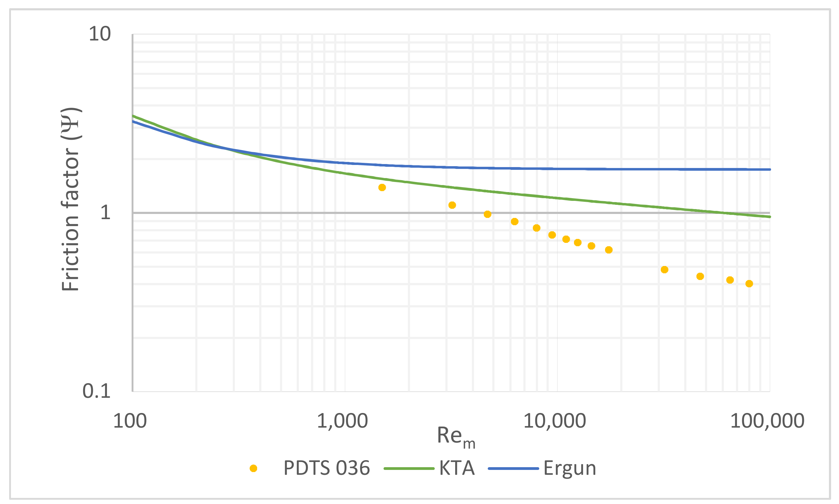
KTA method is another famous equation to predict pressure drop, established by Kerntechnischer Ausschuss (KTA) in 1981, especially for a gas cooled fixed-bed reactor, and its focus is on applicability on higher range of Reynolds numbers. In the literature, it has been mentioned that the experimental results confirmed the validity of KTA equation up to
[
11]. Its original form is
where the coefficient of loss of pressure through friction
is determined in accordance with the following empirical correlation [
12]:
By substituting term 3 in the main formula, and changing
to
, the equation becomes
In the digital age, CFD has become a viable alternative to empirical methods. CFD is a branch of fluid mechanics that is capable to solve flow and energy balances in complicated geometries numerically; endless growth in computer capacity ensures that CFD is one of the fastest growing tools used in computer aided engineering design (CAE). Its popularity has stemmed from the relatively low set-up cost and man-hours compared to a full empirical study, coupled with the generally accepted accuracy of CFD. In addition, far more data, such as instantaneous pressure and velocity fields, could be extracted from CFD than its empirical counterpart [
8]. Commercially available CFD codes use one of three basic spatial discretization methods, finite difference (FD), finite volume (FV), or finite element (FE) [
13]. FD is a differential scheme that is approximation of a Taylor series expansion, bringing in some approximation errors. FV and FE methods are integral schemes which integrate across the area with minimized chance of error, so most of the advanced CFD codes utilize FV or FE method [
14].
CFD, in particular, could help scientists and engineers to understand the characterization of fixed beds [
1]. Establishing a numerical laboratory that can accurately predict the fluid mechanics through structured and unstructured fixed beds is investigated in this work, with the focus on pressure drop calculation.
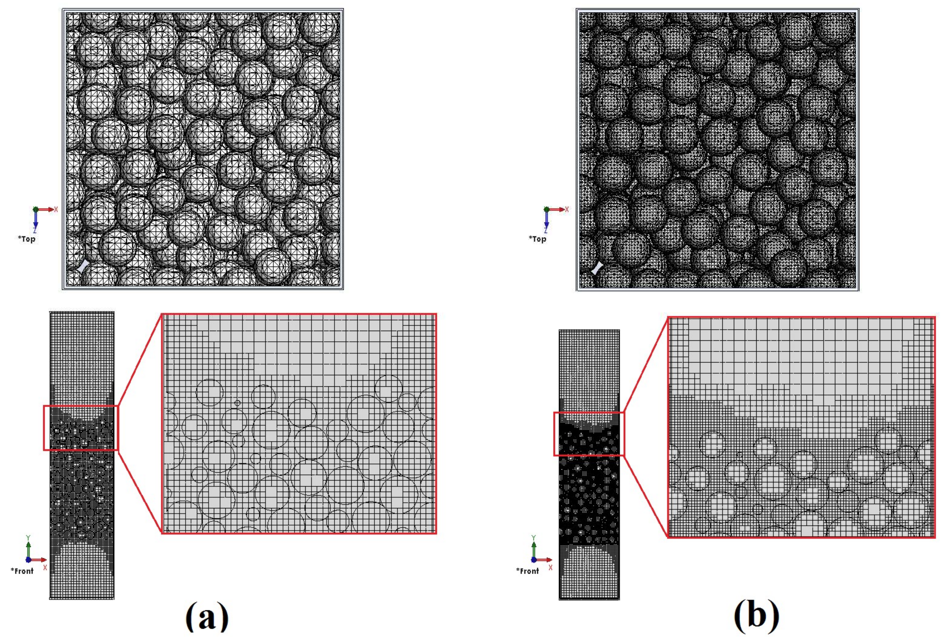
As far as CFD is concerned, there are two methods for simulation of fixed-bed reactors. In the first approach, the bed is modeled using the pseudo-homogeneous approach. In this approach, the effective parameters are defined for dispersion and heat transfer, and the radial profiles are constant along the radial direction of fixed bed. This assumption may lead to errors in the study of transport phenomena in the fixed-bed reactors. The velocity field can be obtained from a modified momentum balance. The continued lumping of transport phenomena is the disadvantage of this method. In the second approach, the particles are placed separately in the bed. This method yields a detailed description of the fluid flow between the particles. The governing equations for the fluid flow are relatively simple, but the geometric modeling and grid generation become complicated. In this method, the contacts between particles together and particles to wall have been taken into account [
15].
Dalman et al. performed CFD simulation of fluid flow and heat transfer around two spherical particles near the wall at
Re < 200 in 2D geometry in 1986 [
16]. In 1996, Derkx and Dixon carried out 3D simulations in the fixed bed using finite element method for three spherical particles [
17]. Calis et al. simulated the pressure drop and drag coefficient in square channels in tube-to-particle diameter ratios between 1 and 2 by using ANSYS CFX [
18]. Guardo et al. investigated pressure drop and heat transfer in the fixed-bed model consisting of 44 spheres in laminar and turbulent flow regimes [
19]. Fluid flow through the array of spheres was studied by Gunjal et al. using the unit-cell approach [
20]. Reddy and Joshi in 2008 attempted to calculate pressure drop and drag coefficient of air moving through 151 particles in eight layers for
Re numbers in range of 0.1 to 10,000, and compared the results with Ergun’s equation [
21]. In 2011, a dissertation dealt with numerous modelling implementations of experiments for different fixed beds that gave interesting insights into the fluid mechanics of flow through fixed beds using Star-CCM+ code for
Re numbers lower than 4000, with nitrogen gas as the fluid [
1].
Forthcoming applications of fixed beds which operate at higher Reynolds numbers, and also systems in which water or supercritical steam is flowing inside the bed, require further research, and finding new equations are needed to predict the pressure drop through fixed bed.
1.3. Supercirtical Steam
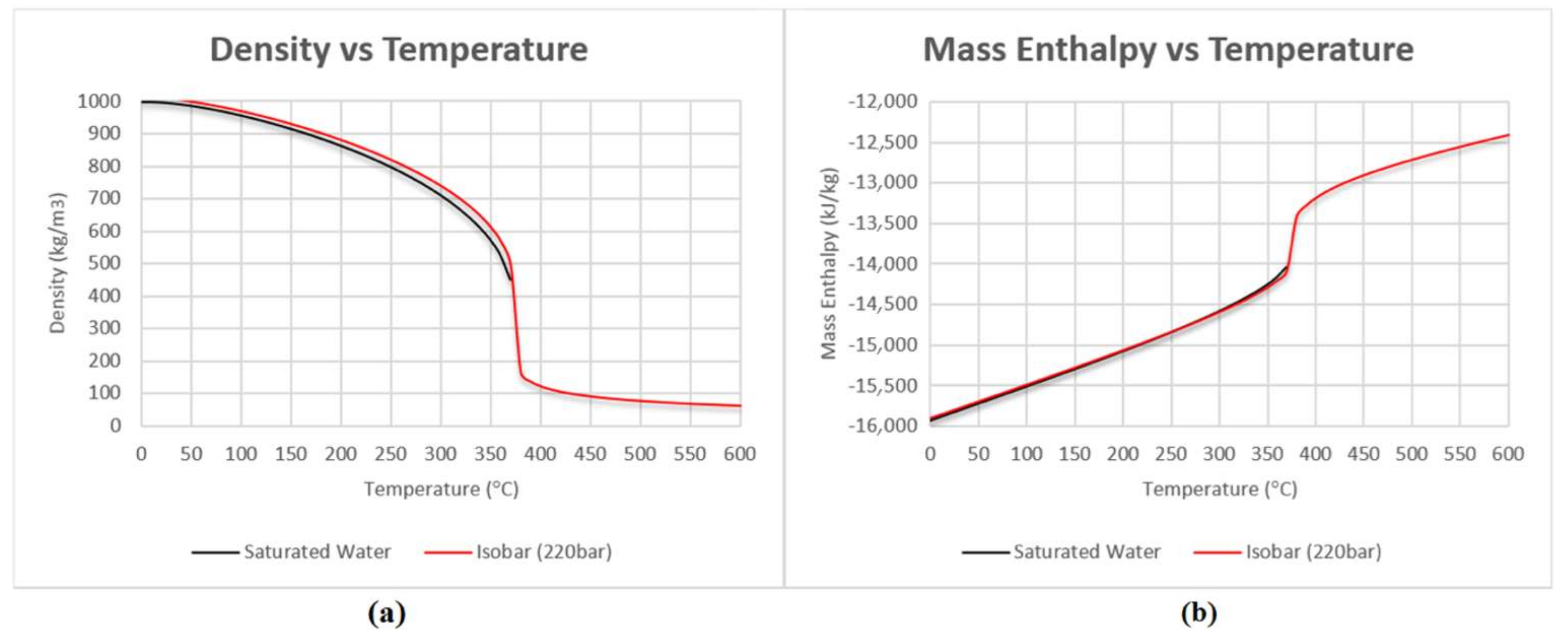
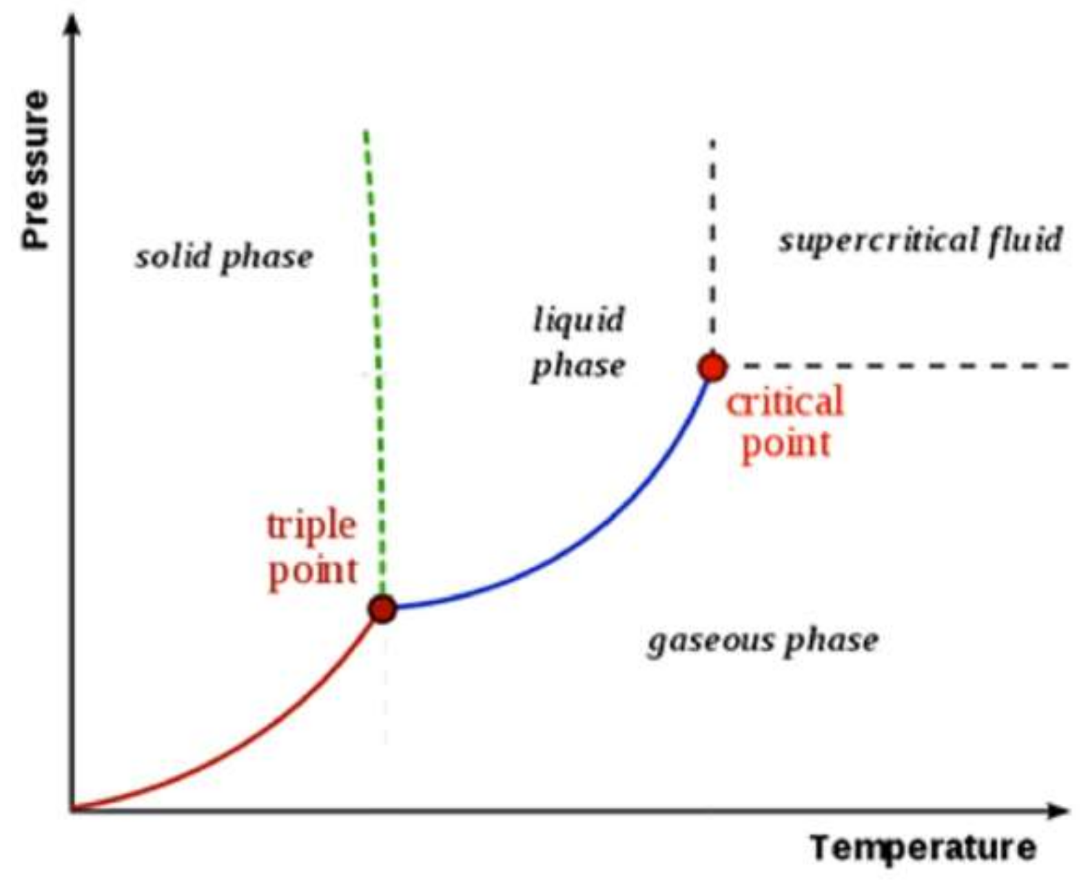
Supercritical steam, which is a special state of water, is a relatively new working fluid in industry that forms part of this research. As can be seen in
Figure 1, the critical point of a fluid marks the terminus of the vapor–liquid coexistence curve. At temperatures above the critical temperature, a fluid cannot undergo a transition to a liquid phase, regardless of the pressure applied. A fluid is “supercritical” when its temperature and pressure exceed the temperature and pressure at the critical point [
22].
Supercritical fluids possess properties that make them attractive as media for chemical reactions. It may be advantageous for reactions involved in fuel processing, biomass conversion, biocatalysts, homogeneous and heterogeneous catalysis, environmental control, polymerization, materials synthesis, and chemical synthesis [
22].
Supercritical steam cycle in particular, creates an improved Rankine cycle at supercritical pressure and temperature, aiming at higher thermodynamic cycle efficiency, and thus, lower power generation costs. Coal fired power plants exist using such supercritical steam cycle since the 1990s [
23]. Recently, more advanced coal-fired over-supercritical (OSC) and ultra-supercritical (USC) steam power plants reached the efficiency of 47% [
24]. In nuclear power plants, water-cooled nuclear reactors operating at subcritical pressures (7–16 MPa) have provided significant electricity production for the past 50 years. However, the thermal efficiency of current nuclear power plants is between 30–35%. Hence, more competitive designs with higher thermal efficiencies, around 45 to 50%, need to be developed and implemented [
25]. Recent design studies of a supercritical steam cycle for nuclear power plants, aiming at higher thermal efficiencies and heat flux, are ongoing. Such reactors have never been built up to now [
23]. The fourth generation FBNR nuclear reactor design is considering the use of supercritical steam as its coolant [
26].


