Mechanical Behavior of Toughened Epoxy Structural Adhesives for Impact Applications
Abstract
1. Introduction
2. Literature Review
2.1. Types of Structural Adhesives
2.2. Epoxy Adhesives
2.3. Polyurethane Adhesives
2.4. Fillers, Reinforcements and Their Effects on Structural Adhesives
2.5. Mechanical Properties and Modeling of Structural Adhesives
Strain Rate Dependency of Structural Adhesives’ Tensile, Compressive and Shear Properties
3. Objectives of the Current Study
- 1—
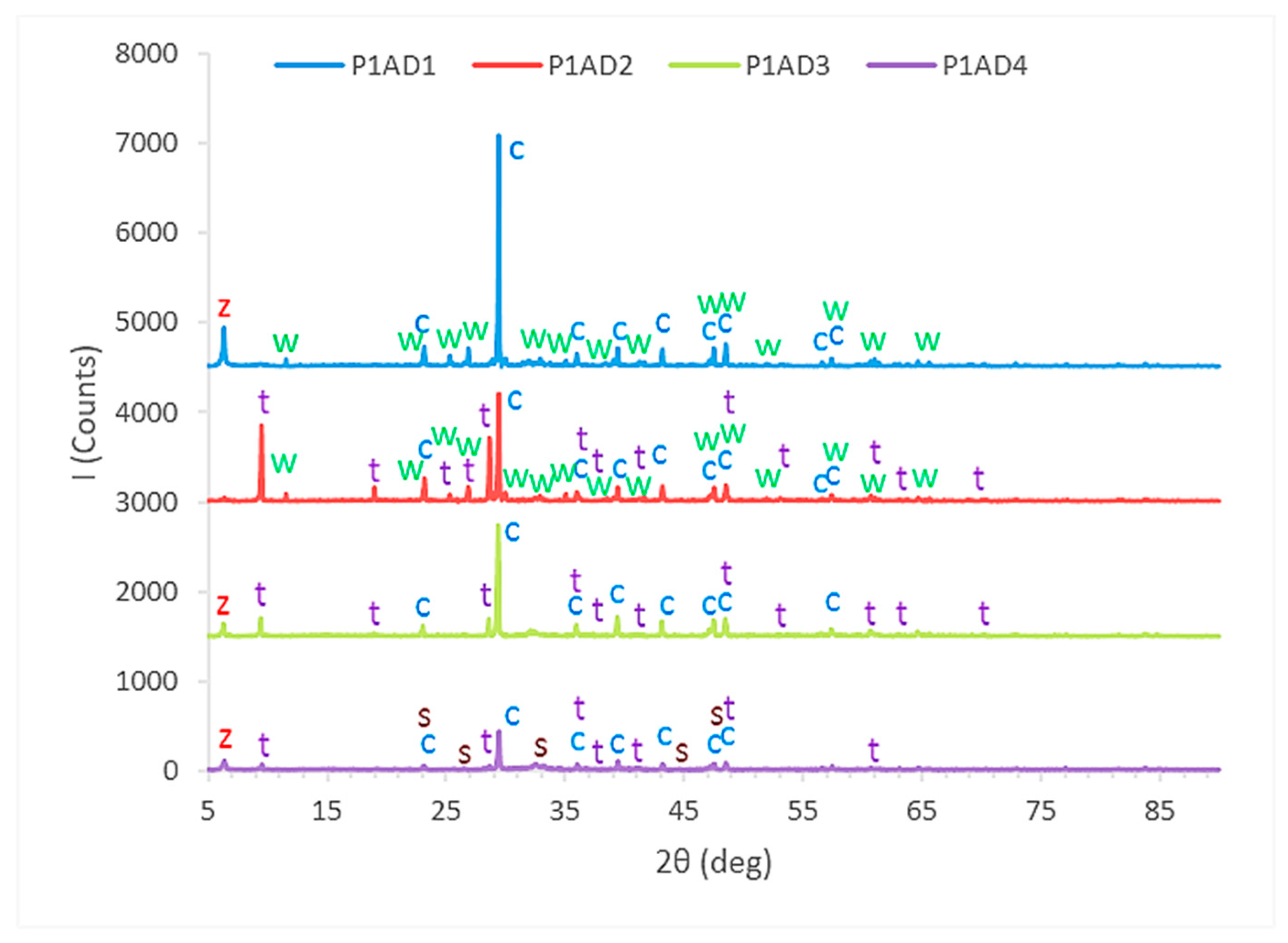
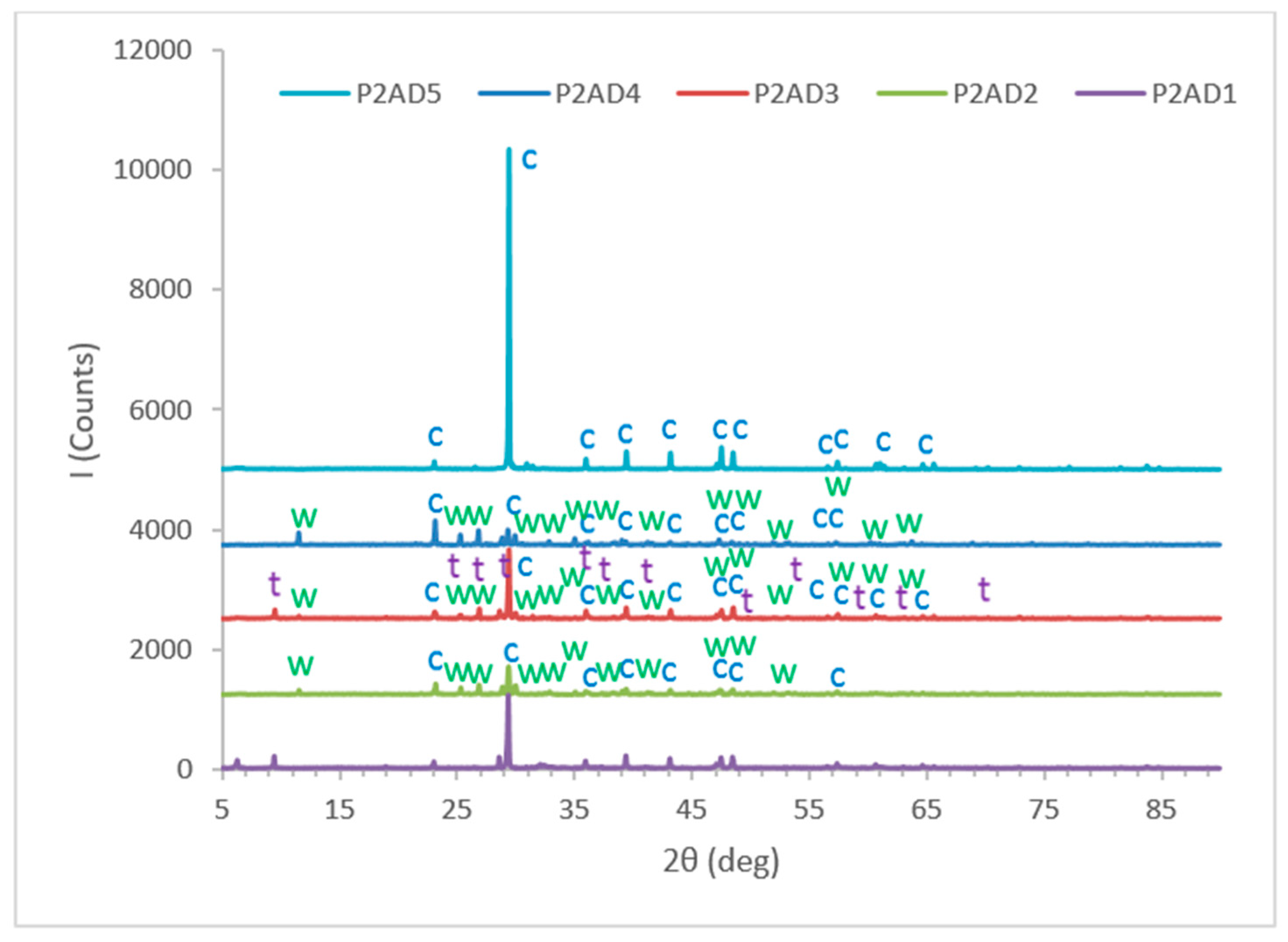
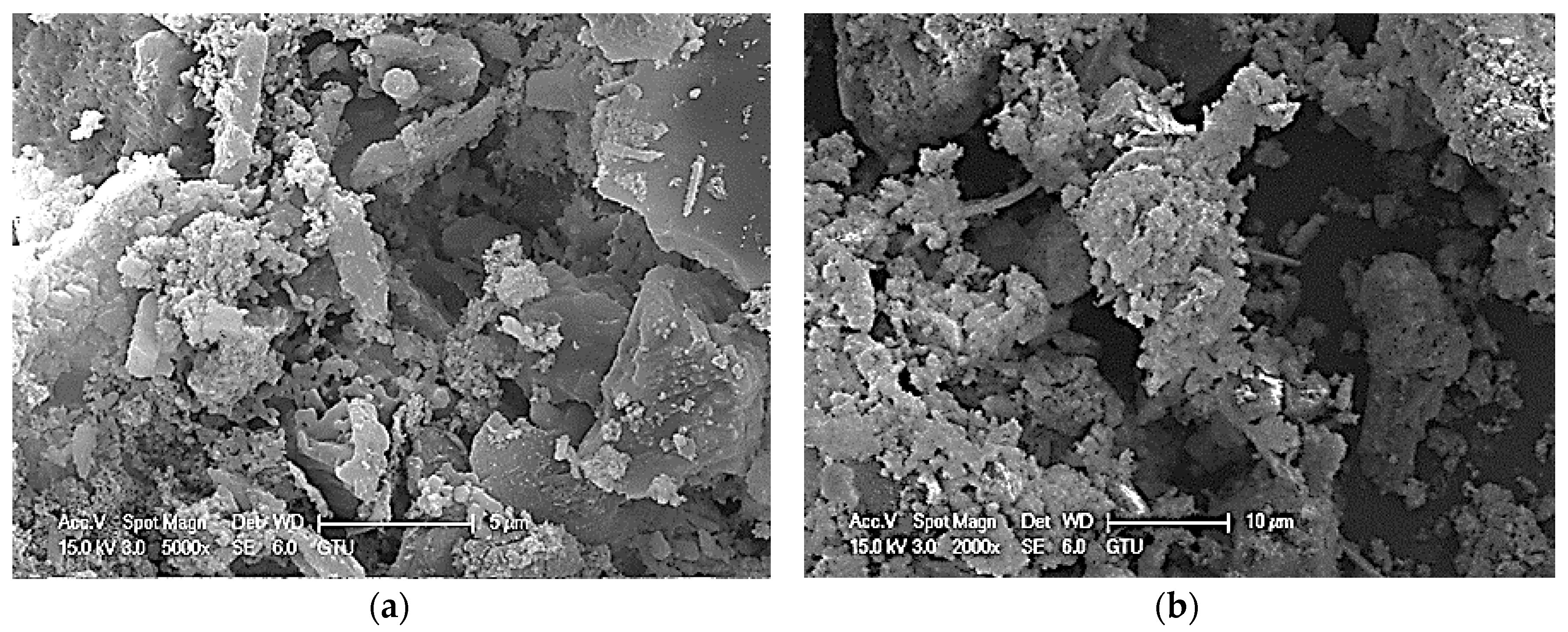
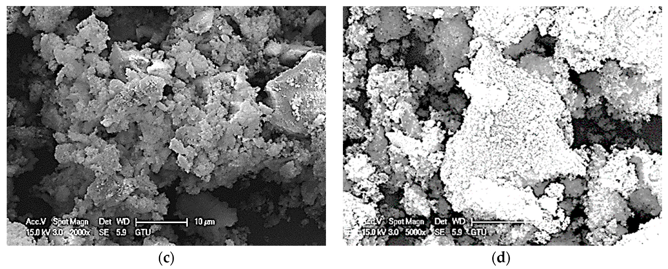
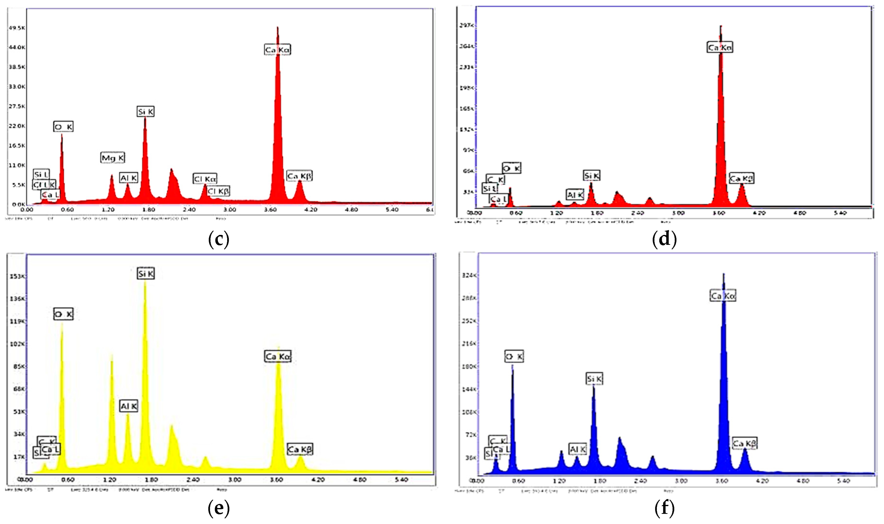
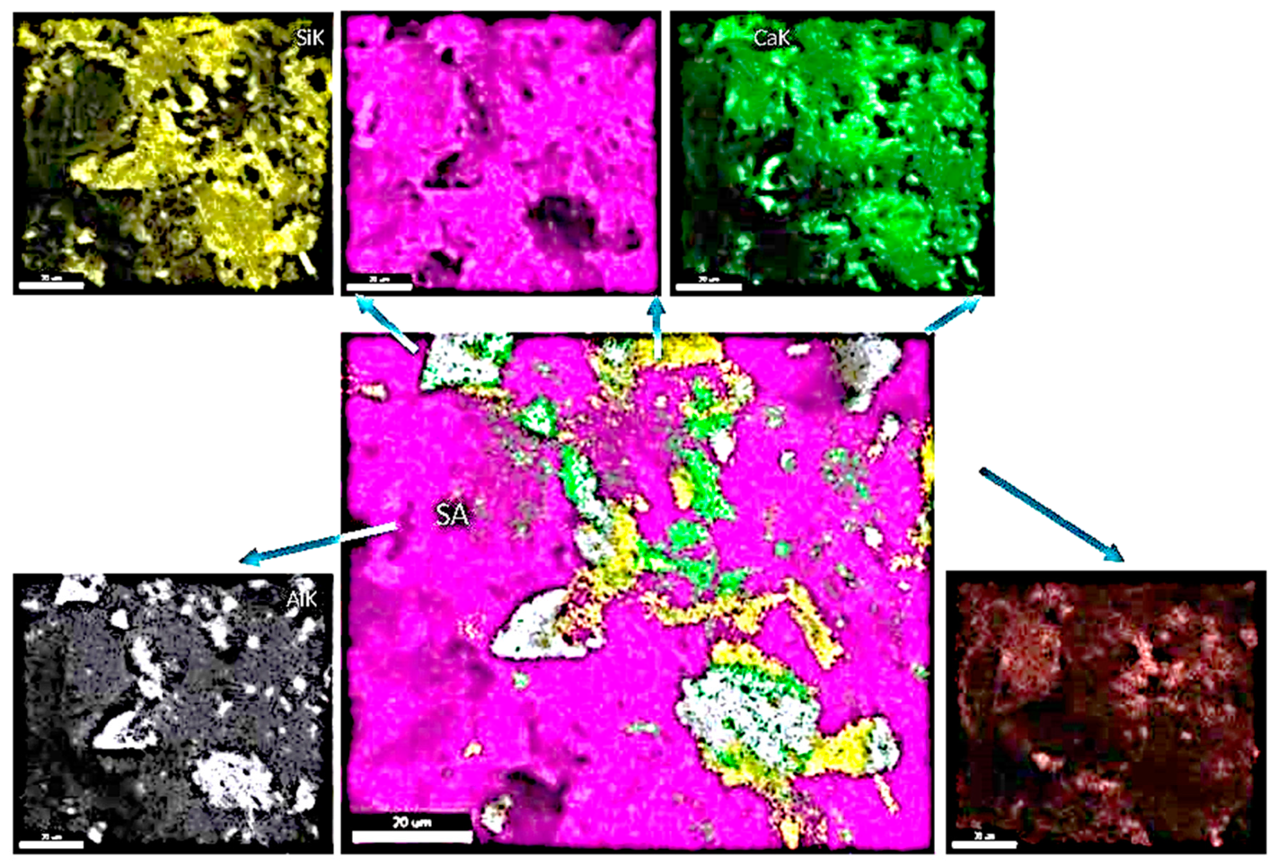
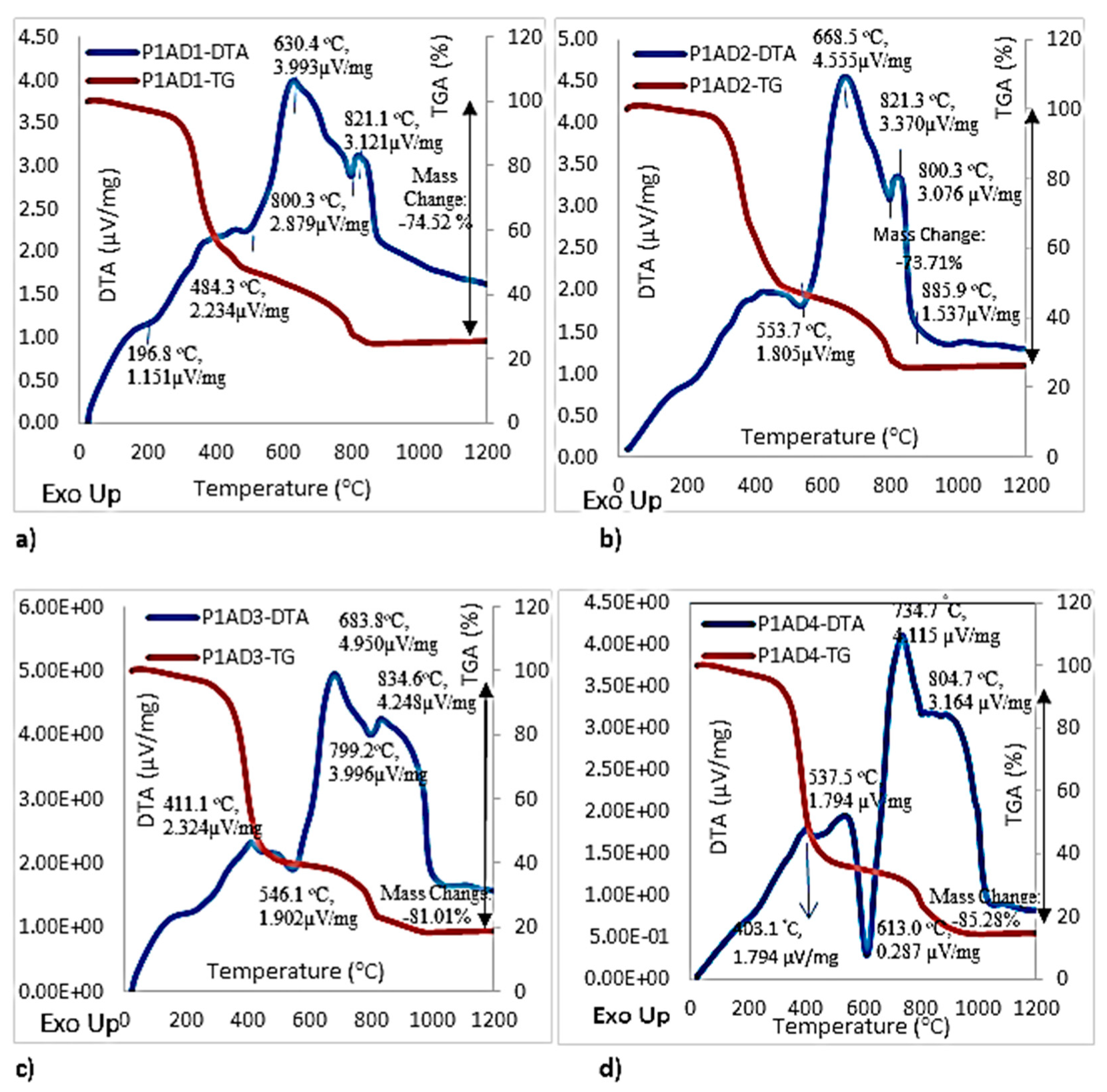
- Detailed information about the constituents of eight different commercial toughened epoxy structural adhesives, used as model materials, will be obtained in order to be able to correlate them to their mechanical and failure behavior in bulk and bonded forms. These model adhesives will be divided in two groups as category 1 and category 2. Adhesives used in first category, adhesives 1, 2, 3 and 4, are labeled as P1AD1, P1AD2, P1AD3 and P1AD4, respectively, and they will be used to perform bulk tensile tests at different crosshead rates using a universal testing machine. Adhesives used in second category, adhesives 1, 2, 3, 4 and 5, are labeled as P2AD1, P2AD2, P2AD3, P2AD4 and P2AD5, respectively and will be used to perform impact tests using a split Hopkinson pressure bar (SHPB) apparatus at high strain rates (P1AD3 and P2AD1 are the same adhesives). Adhesives will be characterized by X-ray diffraction (XRD), differential thermal analysis (DTA), thermogravimetric analysis (TGA), scanning electron microscope (SEM) and energy dispersive x-ray spectrometer (EDS). The main crystalline inorganic ingredients will be identified as calcite (limestone), calcium oxide and wollastonite for all types of adhesives using combination of XRD, EDS analyses results and material safety data sheets (MSDS).
- 2—
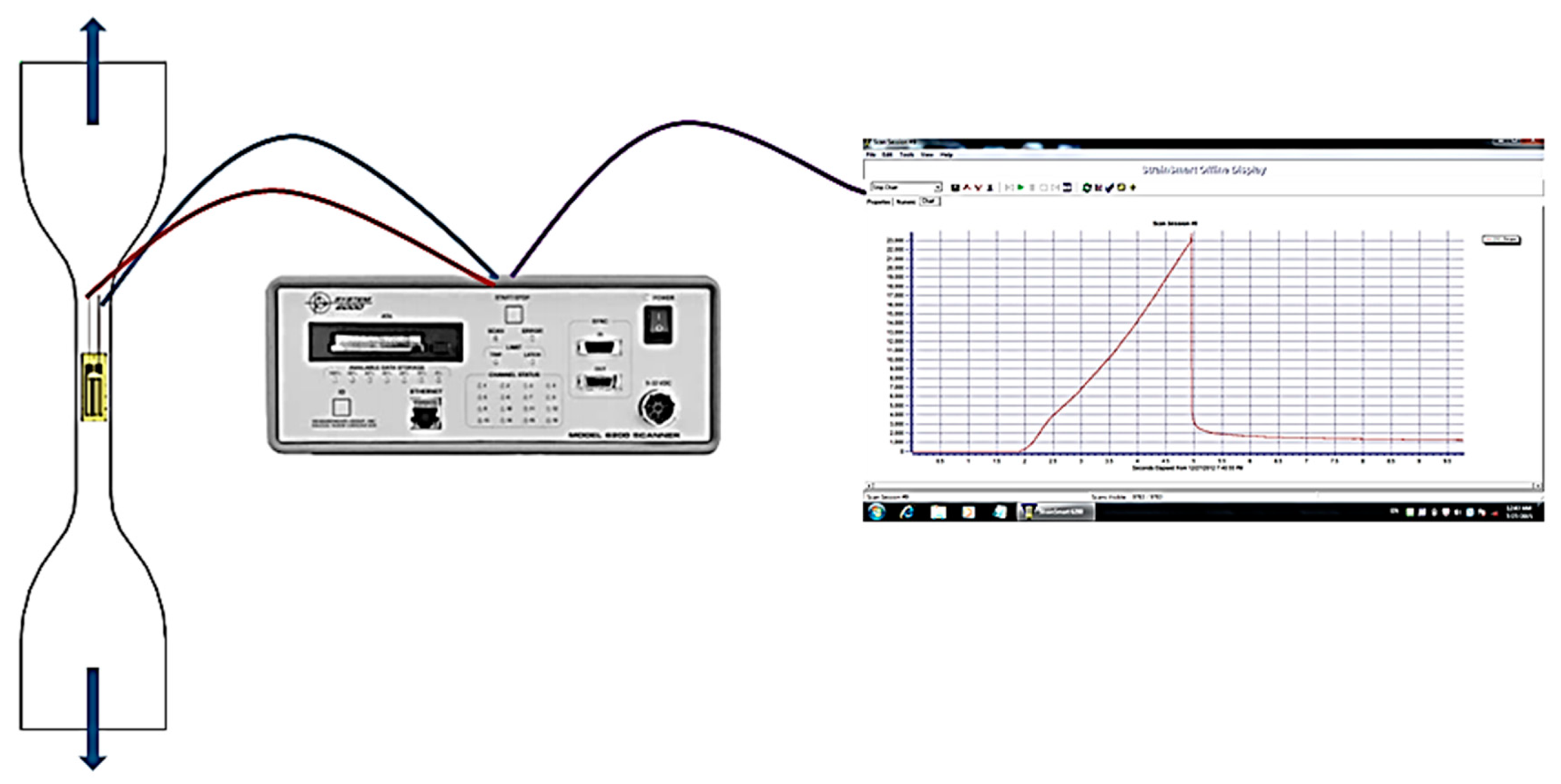
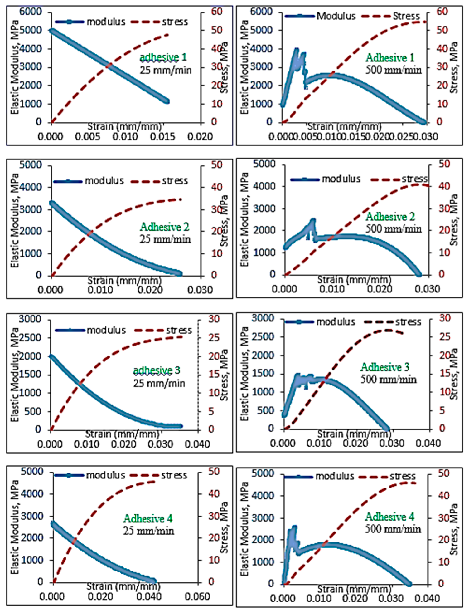
- Tensile tests will be performed with strain gages attached to the specimens in order to identify the effect of strain rate on the material parameters of 4 different toughened epoxy structural adhesives involved in first category; adhesive 1, 2, 3 and 4. Stress–strain behavior of adhesives will be modeled using elastic-viscoelastic-plastic behavior representation using one-dimensional (1-D) phenomenological mechanical modeling approach which involves spring, dashpot and sliding element analogies.
- 3—
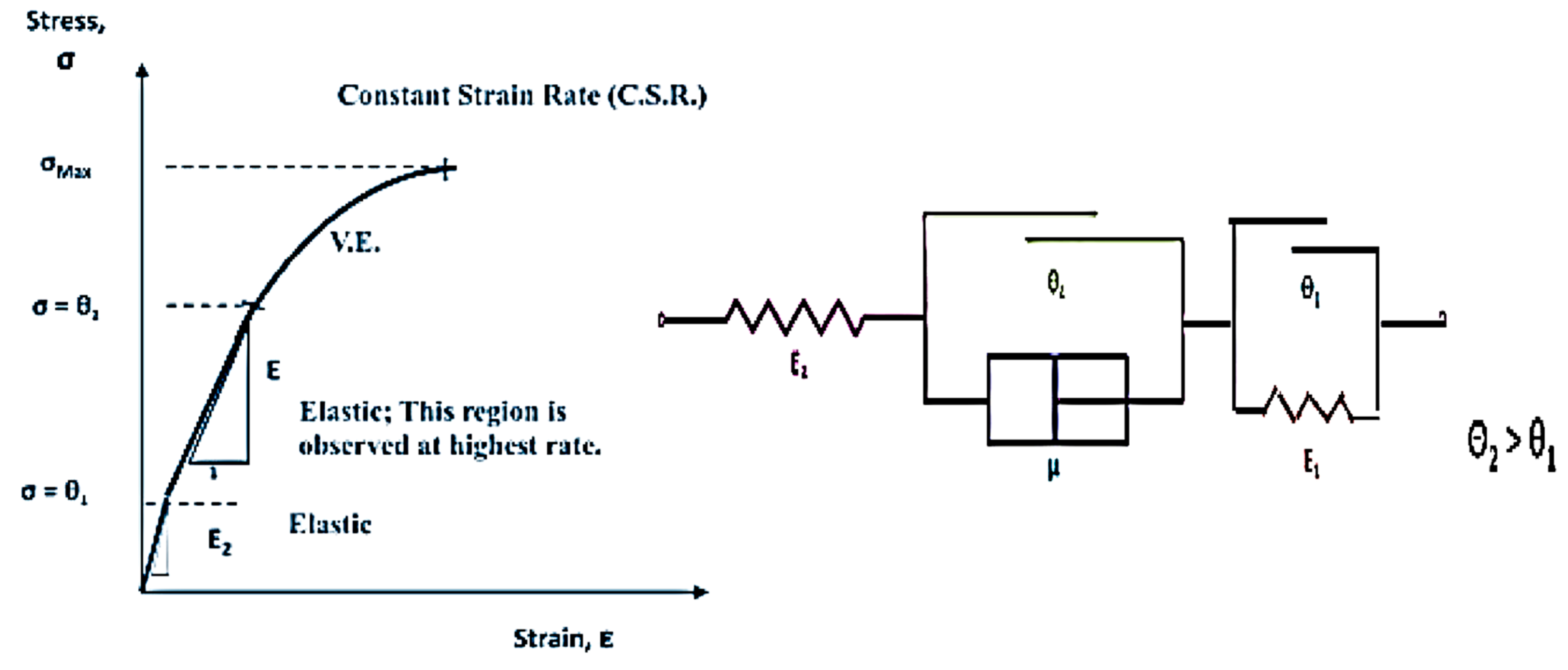
- The strain rate sensitivity will be described by incorporating Ludwik-type equations into our modeling process. For this purpose, the modified Bingham elastic-viscoelastic-plastic model will be altered to a novel configuration to accommodate possible multilinear-elastic regions predicted with pronounced elasticity usually observed at high strain rates and impact situations. The stress–strain behavior of adhesives will be captured with high statistical accuracy in tensile mode at different extension rates from 25 mm/min to 500 mm/min.
- 4—
- Toughness values will be calculated using this tensile stress–strain data in order to obtain insight into the effects of adhesive constituents (fillers and tougheners) and strain rate on the energy absorption behavior of the model adhesives in bulk form.
- 5—
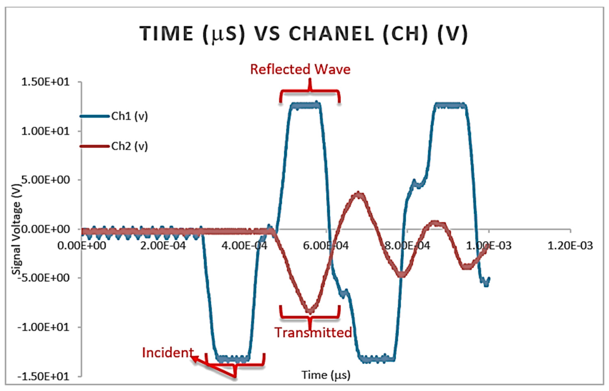
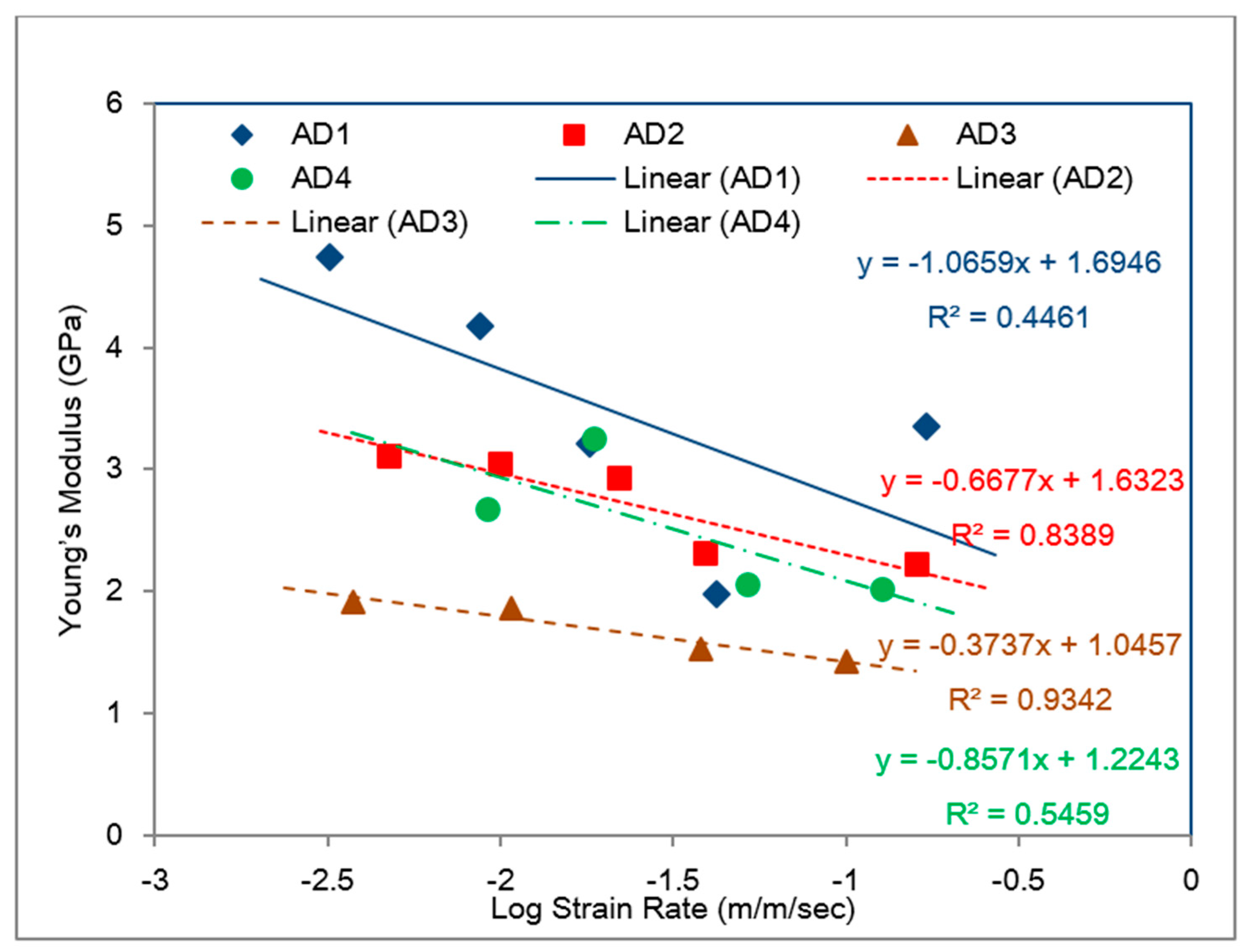
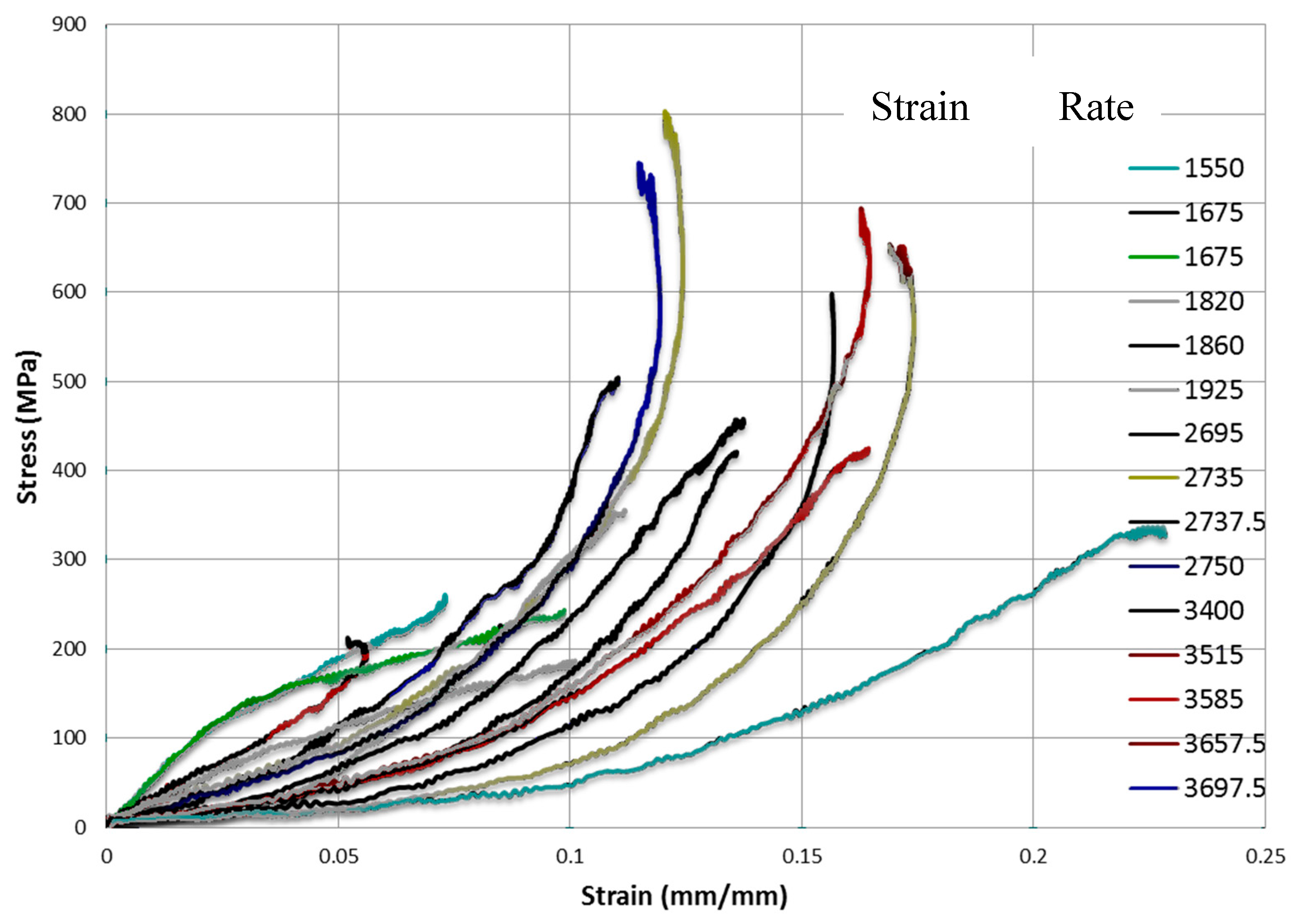
- Split Hopkinson pressure bar (SHPB) test will also be employed at high strain rates under compression to unveil the high rate (impact) behavior of adhesives involved in second category: adhesive 1, 2, 3, 4 and 5. These tests will be performed to assess whether the modeling performed in tensile mode using extension rates from 25 mm/min to 500 mm/min adequately represent higher rate impact behavior if we assume that such an impact event is dominated by elastic behavior, interfacial separations of the adhesive components and fast cohesive failures within the adhesive. For this purpose, the elastic moduli obtained via SHPB test will be compared with the elastic moduli obtained from the tensile specimens to validate the model developed as well as confirming the strain rate dependency of the model adhesives.
- 6—
- The bonded (adhesive) behavior of the model materials will be evaluated for accurate assessment on the high-rate (impact) behavior of these novel crash resistant adhesives when bonding automotive steel substrates in typical lap joint configuration. The toughness values of the model adhesives will be compared when tested in bulk tensile and single lap bonded forms to assess the effects of main factor(s) in adhesive make up and loading rate (impact) on energy absorption capacity of the model adhesives.
4. Materials and Their Characterization
4.1. Materials
Composition of Materials obtained from Supplier
4.2. In-House Characterization of Materials
4.2.1. X-ray Diffraction (XRD) Analysis of Toughened Structural Adhesives
4.2.2. SEM/EDS ANALYSIS
Model Adhesives used in Tensile Testing (Phase 1)
Model Adhesives Used in Split Hopkinson Pressure Bar (SHPB) Testing (Phase 2)
4.2.3. Differential Thermal Analyses and Thermogravimetric Analyses
DTA and TGA for Adhesives Used in First Phase of the Study
DTA and TGA for Adhesives Used in Second Phase of the Study
4.2.4. Tensile Testing
4.2.5. Bonded Single Lap Shear Testing
- Substrates were cleaned with acetone.
- Substrates were marked away from the overlap area to calculate substrate deformation used in obtaining accurate adhesive strain;
- Adhesive was applied to the substrate on 25.4 mm x 12.7 mm overlap area according to the ASTM standard;
- Shims were used to define adhesive thickness;
- Substrate was joined and pressurized using binder clips;
- A convection oven was used to cure the specimens at 180 °C for 30 min which were then allowed to cool;
- The overlap area and the thickness were recorded for further calculations;
- Single lap specimens were tested in tensile-shear mode (ASTM D1002) using an Instron 5567 electro-mechanical test machine at different extension rates between 25 mm/min and 500 mm/min. Extension versus load curves were obtained from the Instron data processor.
4.2.6. Split Hopkinson Pressure Bar (SHPB) Testing
Sample Calculation for SHPB Testing
5. Results and Discussion
5.1. Identification of Rate Dependent Material Parameters of Toughened Structural Adhesives
5.2. Modeling of Rate-Dependent Material Parameters for Toughened Structural Adhesives
5.3. Comparison with SHPB Tests
5.4. Determination of Rate Dependent Parameters of the Bilinear-Viscoelastic Model for Tensile Loading
5.5. Rate Dependence of Adhesive Toughness
5.6. Bonded Single Lap Shear Testing of 1st Phase Adhesives
6. Summary and Conclusions
- When the change in the mass (during TGA tests) of the impact-resistant adhesives were compared for the first phase of this study (involving bulk tensile tests at different crosshead rates using a universal testing machine), it was seen that adhesive 2 had the highest amount of inorganic fillers with a 26.29 wt % residual amount of weight, whereas adhesive 4 had the least amount of inorganic fillers with 14.72 wt % residual amount of weight. The important common observation from all DTA curves of adhesives 1–4 is the fact that a large amount of energy was absorbed beyond mid six-hundred degrees centigrade through processes involving decomposition of weakly crystalline calcite followed by the decomposition of well crystallized calcite. Prior to and during these processes, energy was also absorbed by decarbonation occurring due to the decomposition of carbonates and loss of carbon dioxide from calcite.
- When the change in the mass of adhesives were compared for the second phase of this study (involving impact tests using a split Hopkinson pressure bar (SHPB) apparatus at high strain rates), it was seen that adhesive 3 had the highest amount of inorganic fillers with 27.59 wt % residual amount of weight whereas adhesive 5 had the least amount of inorganic fillers with a 17.48 wt % residual amount of weight. As in the case of Phase 1 adhesives, the important common observation from all DTA curves of Phase 2 adhesives is the fact that a large amount of energy was absorbed at higher temperatures (>700 °C) through processes involving decomposition of weakly crystalline calcite followed by the decomposition of well crystallized calcite. Prior to and during these processes, energy was also absorbed by decarbonation occurring due to the decomposition of carbonates and loss of carbon dioxide from calcite.
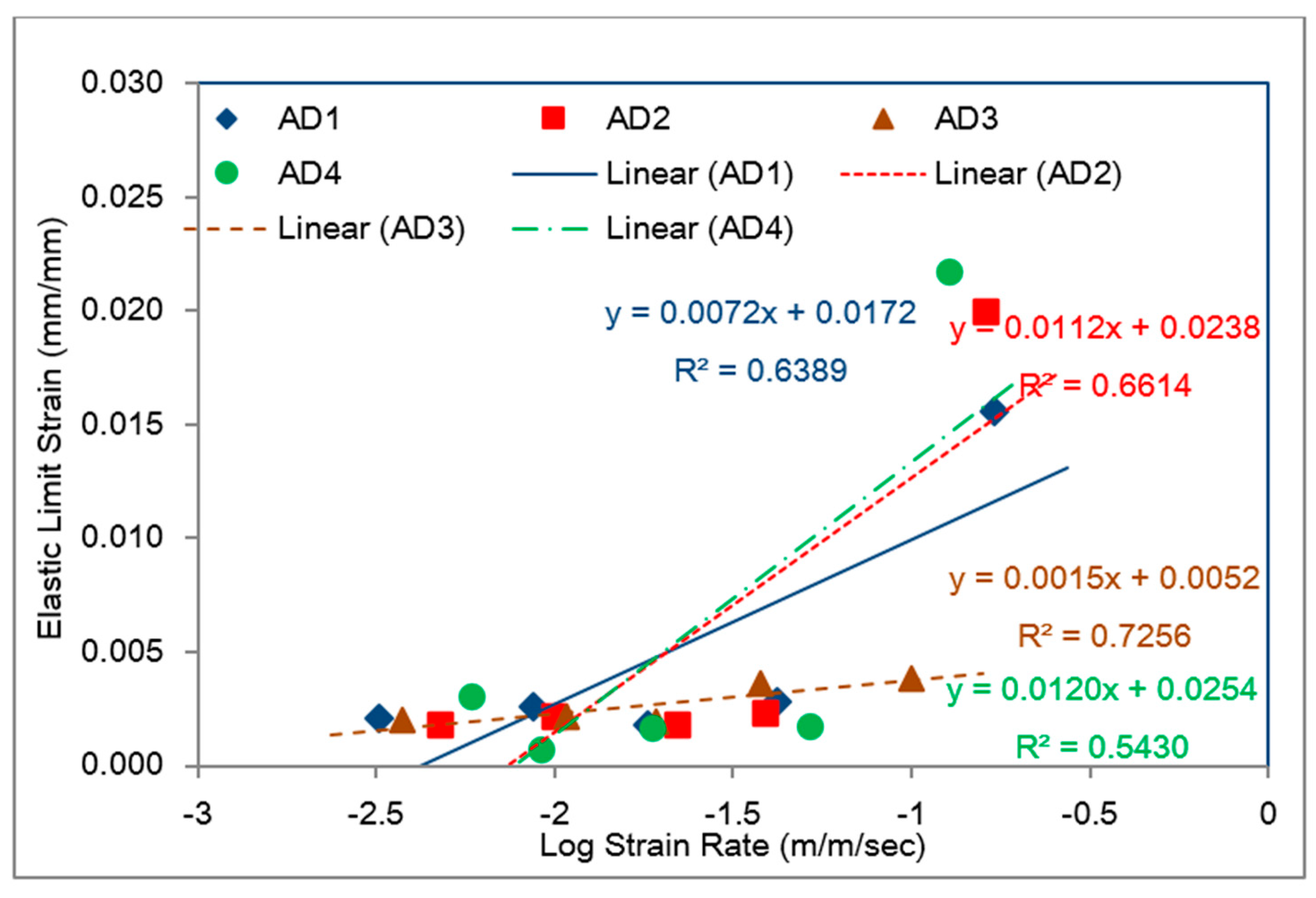
- The bulk tensile stress–strain data for the impact-resistant adhesives revealed that the initial elastic behavior at 500 mm/min extension rate was bilinear. In order to represent this initial bilinear elastic behavior, modification of the modified Bingham model to a new bilinear-viscoelastic model was proposed. Thus, equivalent elastic moduli, E1 and E2 were introduced which individually represented the elastic behavior of the toughened adhesive materials in composite morphologic form. The tensile data revealed that Young’s modulus, E2 for all adhesives decreased with increasing strain rate and similar behavior was also observed with split Hopkinson pressure bar (SHPB) testing. Remarkably, the modulus magnitudes seem to be similar between the tensile test and SHPB specimens.
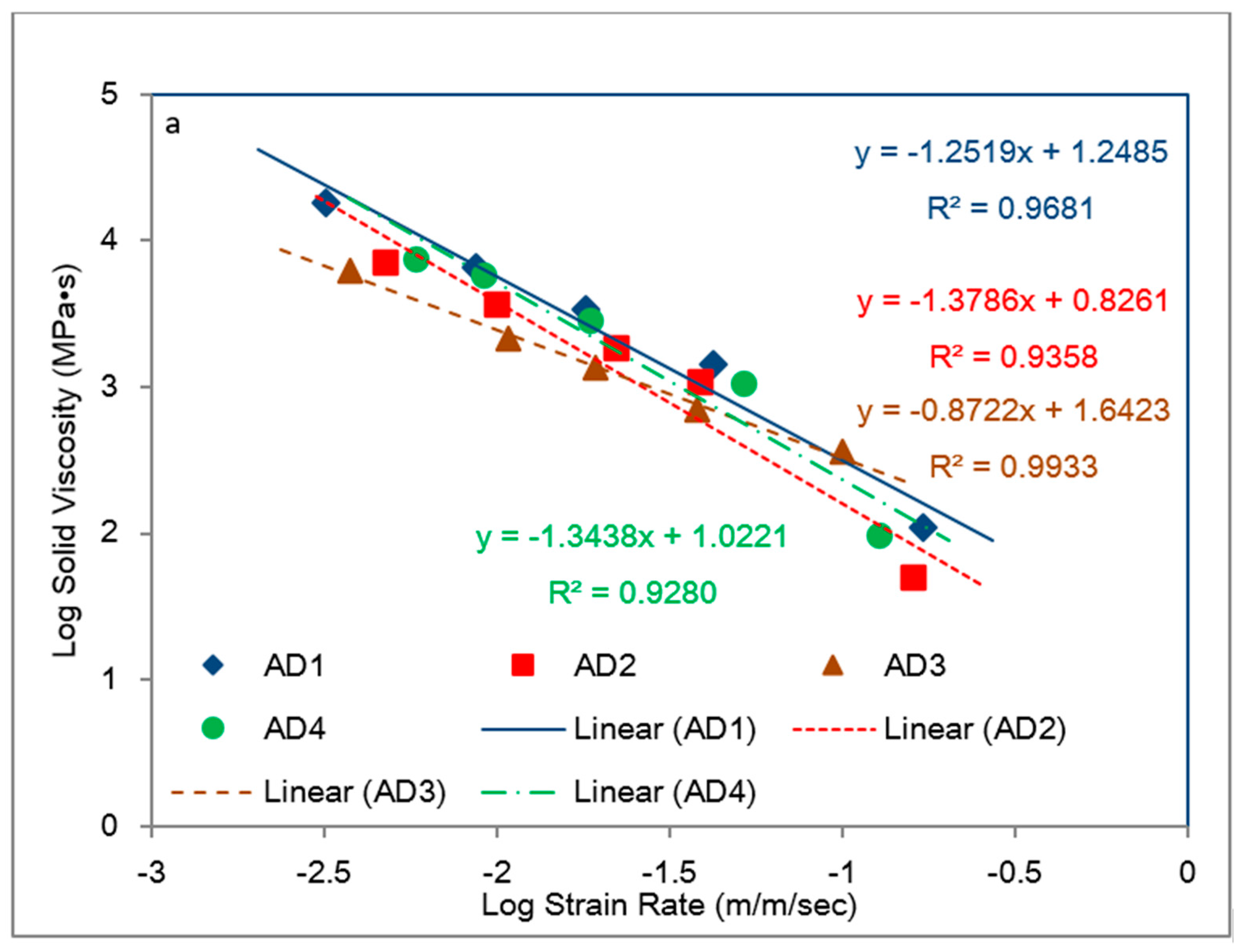
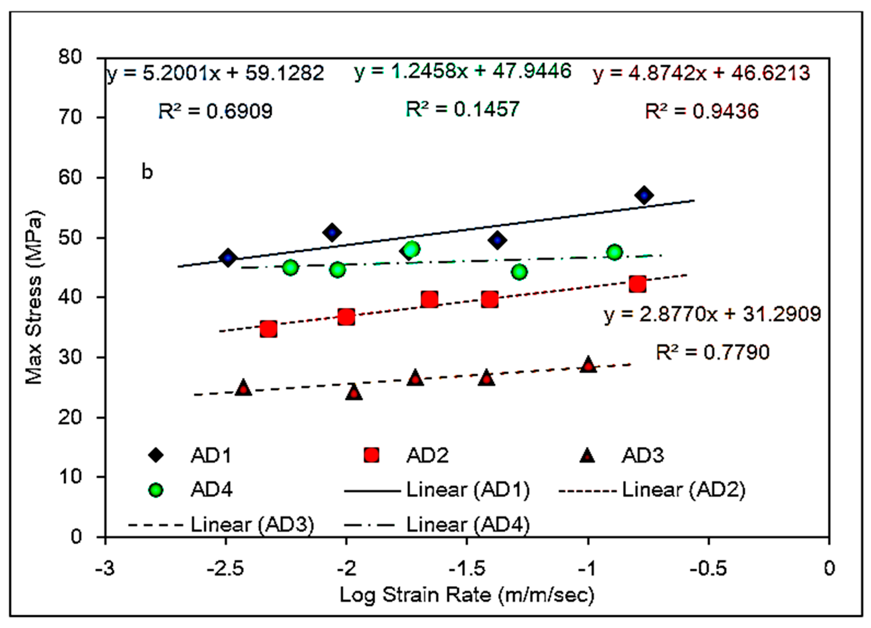
- Based on the slopes of the Ludwik-type linear regression lines for the tensile stress–strain data, Young’s modulus, E2, for adhesive 1 had the highest sensitivity to strain rate followed by adhesive 4 and adhesive 2, respectively. Young’s modulus for adhesive 3 was found less sensitive to the strain rate.
- The average toughness–strain rate behaviors of the model adhesives revealed that adhesive 1 had the lowest toughness at the lowest strain rate, but it also had the highest slope in its regression line, indicating it to be the most desirable adhesive for impact applications. It is interesting to note that, all adhesives used in first phase contained elastomeric tougheners in the form of carboxyl terminated butadiene acrylonitrile (CTBN) copolymer, as well as polyurethane adducts besides inorganic fillers except for adhesive 1. Only adhesive 1 used in first phase included just inorganic fillers. Adhesive 4 had the highest toughness for the strain rate range shown, but its toughness seems to be fairly constant (i.e., rate independent), which is an undesirable feature for an impact resistant adhesive. It contained the least amount of inorganic fillers with 14.72 wt %, which was made up of calcite, talc zeolite and calcium silicate.
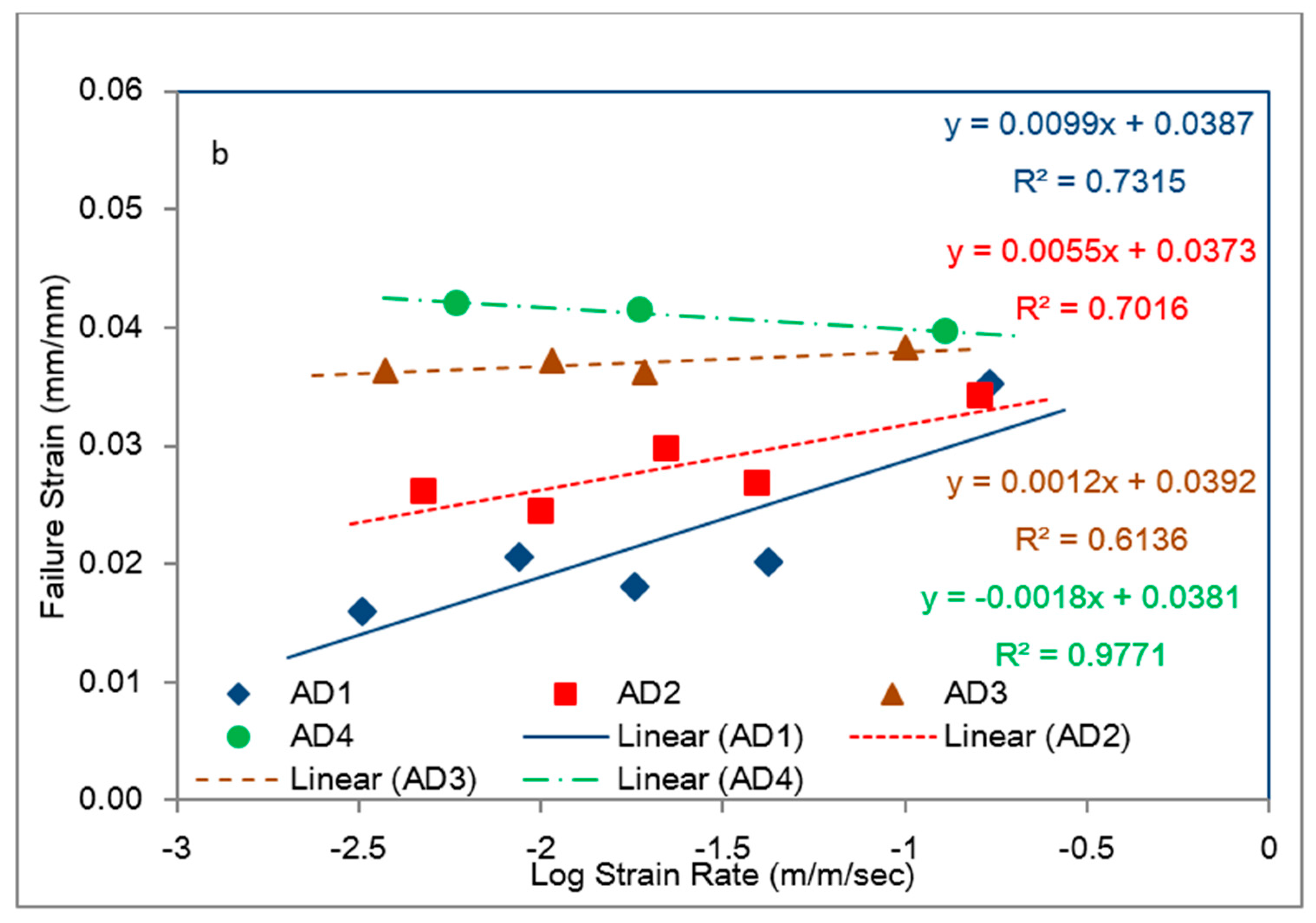
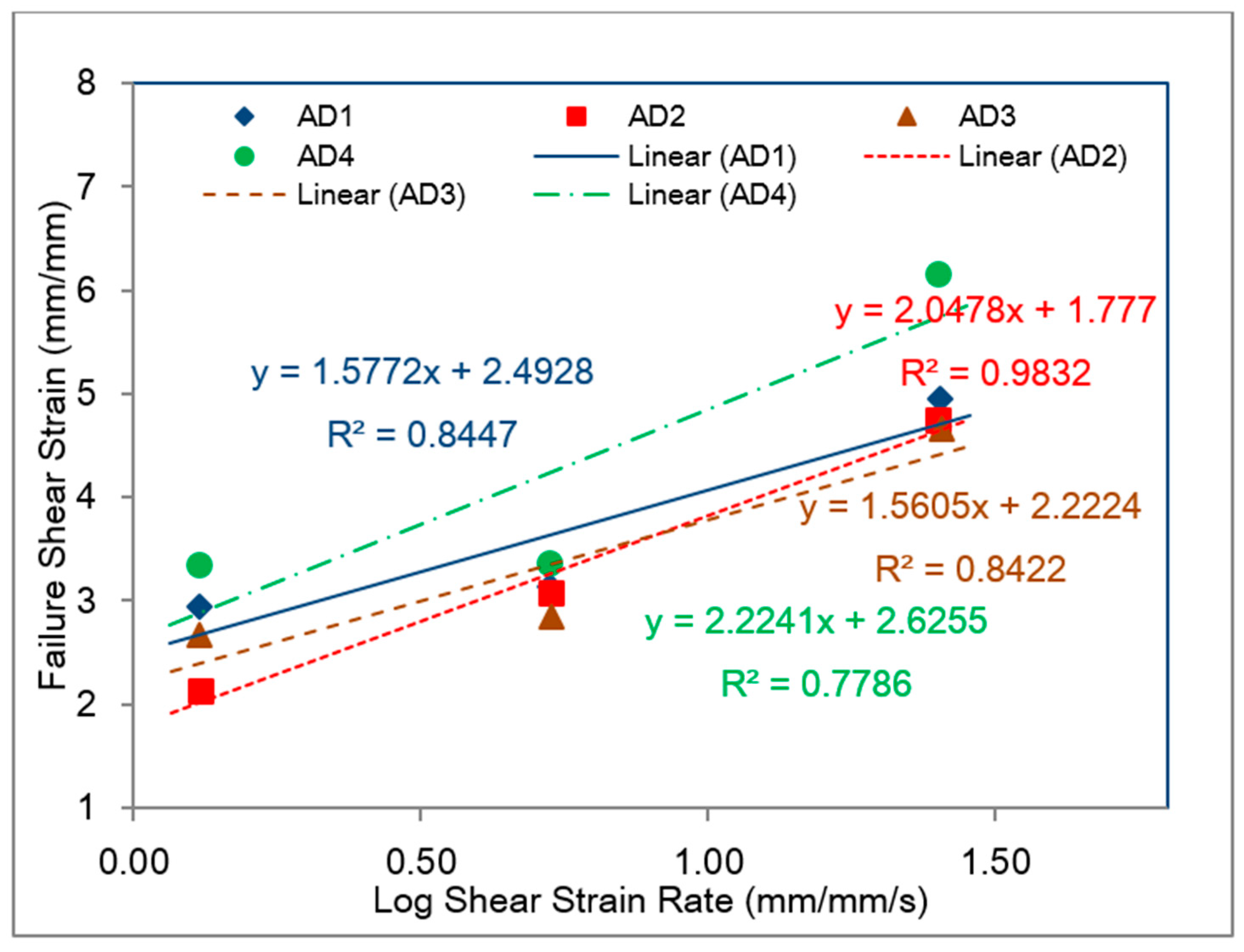
- When the results from bulk (tensile) and bonded (shear) specimens were compared, it was clearly seen that the toughness responses of the adhesives to (tensile/shear) strain rates in the bulk and bonded forms, respectively, were different. The shear toughness values in the bonded form were remarkably higher than those for the bulk tensile specimens with the bonded shear toughness values in the ~25 to ~120 MJ/m3 range within ~1.25 to ~25 mm/mm/s shear strain range in comparison to ~0.5 to ~1.35 MJ/m3 within the ~3 × 10⁻³ to 0.18 m/m/s strain rate range for the 1st Phase adhesives tested in bulk tensile mode. This difference was due to the remarkable increase in the failure strain values for the model adhesives when tested in the bonded single lap shear configuration.
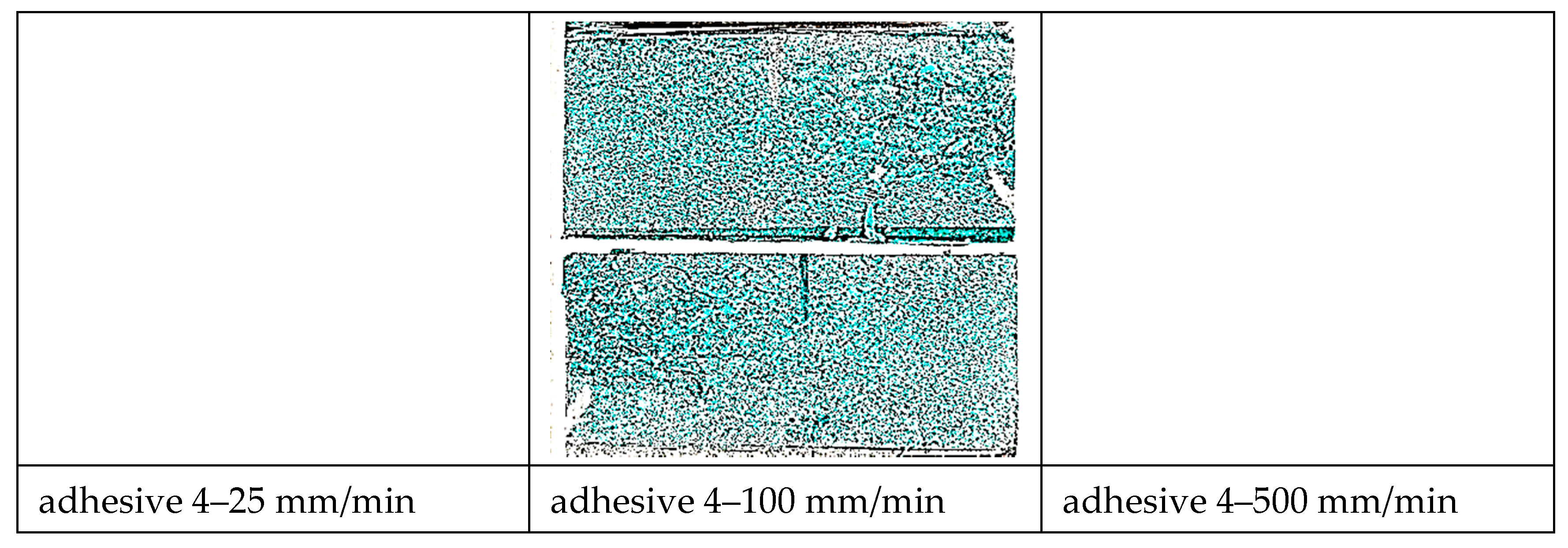
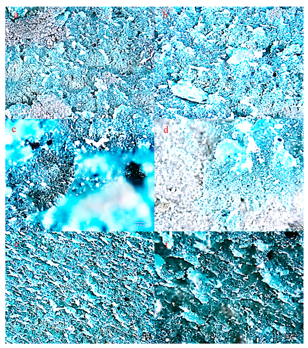
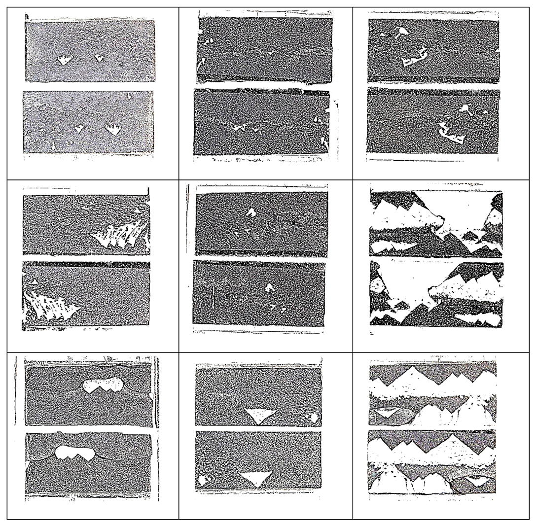
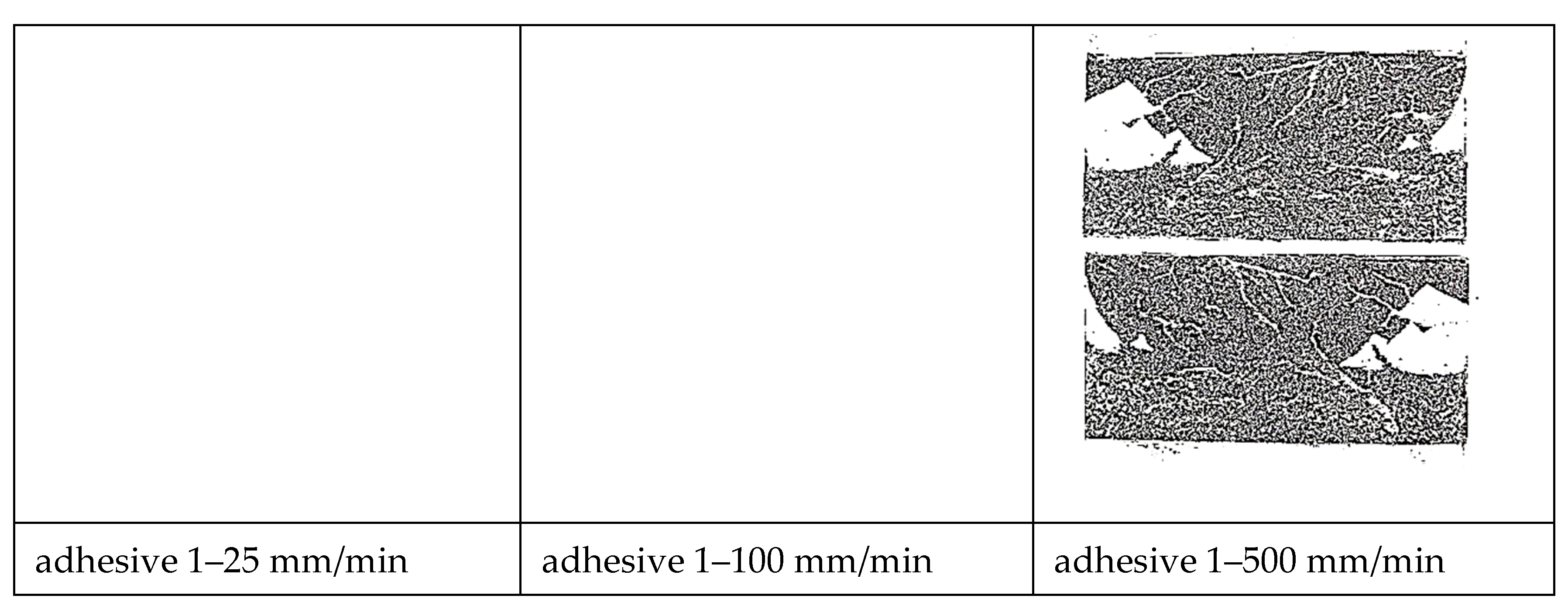
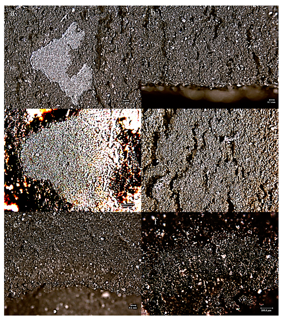
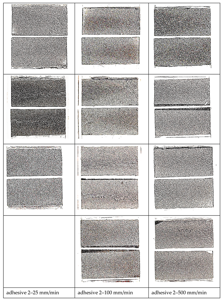
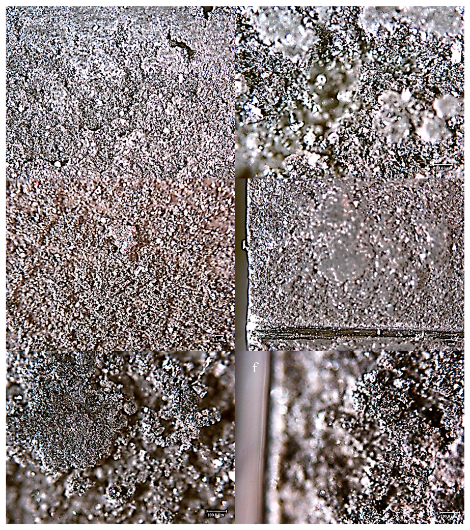
- Based on bonded lap shear data, adhesive 4 had the highest toughness in all shear strain rates followed by adhesive 1. Failure surface observations revealed that the model adhesive which included just inorganic fillers (adhesive 1) and had the lowest tensile toughness at the lowest tensile strain rate, but the highest slope in its tensile toughness regression line, exhibited the second highest bonded shear toughness. When tested at the extension rates of 25 mm/min and 100 mm/min in bonded lap shear, the same adhesive exhibited limited interfacial failure areas, however the dominant failure mode was cohesive failure. When the extension rate increased further, transition to interfacial (adhesive) failure was observed revealing that interfacial failures do not necessarily diminish adhesive bond toughness.
- Thus, our observations point to the fact that cohesive deformation/failure processes indicating interfacial separations, inter-particle interactions as well as polymer matrix deformation in high deformation loading scenario as in bonded shear loadings may provide the highest toughness. Apparently, a large filler weight fraction was not necessary to obtain high shear toughness in bonded form since adhesive 4 had the least amount of inorganic fillers among the model adhesives with 14.72 wt %.
Author Contributions
Funding
Conflicts of Interest
References
- Available online: https://www.epa.gov/regulations-emissions-vehicles-and-engines/final-rule-model-year-2017-and-later-light-duty-vehicle (accessed on 1 May 2020).
- Thryft, A.R. Automotive Structural Adhesives Drive Material Changes. Des. News 2014. Available online: https://www.designnews.com/materials-assembly/automotive-structural-adhesives-drive-material-changes/60752819443699 (accessed on 1 May 2020).
- Chang, B.; Shi, Y.; Dong, S. Comparative studies on stresses in weld-bonded, spot-welded and adhesive-bonded joints. J. Mater. Process. Technol. 1999, 87, 230–236. [Google Scholar] [CrossRef]
- Tao, W.; Ma, Y.; Chen, Y.; Li, L.; Wang, M. The influence of adhesive viscosity and elastic modulus on laser spot weld bonding process. Int. J. Adhes. Adhes. 2014, 51, 111–116. [Google Scholar] [CrossRef]
- Chang, B.; Shi, Y.; Lu, L. Studies on the stress distribution and fatigue behavior of weld-bonded lap shear joints. J. Mater. Process. Technol. 2001, 108, 307–313. [Google Scholar] [CrossRef]
- Real Time Traffic Accident Statistics. Available online: http://www.icebike.org/real-time-traffic-accident-statistics/ (accessed on 1 May 2020).
- Korosec, K. 2016 Was the Deadliest Year on American Roads in Nearly a Decade. Fortune February 15 2017. Available online: https://fortune.com/2017/02/15/traffic-deadliest-year/ (accessed on 1 May 2020).
- Dunn, D.J. Engineering and Structural Adhesives; iSmithers Rapra Publishing: Akron, OH, USA, 2004; Volume 15. [Google Scholar]
- Dillard, D.A. Advances in Structural Adhesive Bonding; Elsevier BV: Amsterdam, The Netherlands, 2010. [Google Scholar]
- Hartshorn, S.R. Structural Adhesives: Chemistry and Technology; Springer Science & Business Media: New York, NY, USA, 2012. [Google Scholar]
- Adams, R.D.; Wake, W.C. Structural Adhesive Joints in Engineering; Springer Science and Business Media LLC: New York, NY, USA, 1984. [Google Scholar]
- Moreira, P.M.; da Silva, L.F.M.; Castro, P.M.S.T. Structural Connections for Lightweight Metallic Structures; Springer: New York, NY, USA, 2012. [Google Scholar]
- da Silva, L.F.; Öchsner, A.; Adams, R.D. Handbook of Adhesion Technology; Springer Science & Business Media: New York, NY, USA, 2011. [Google Scholar]
- Skeist, I. Handbook of Adhesives; Springer Science & Business Media: New York, NY, USA, 2012. [Google Scholar]
- Durig, J.D. Comparisons of epoxy technology for protective coatings and linings in wastewater facilities. J. Prot. Coat. Linings 2000, 17, 49–54. [Google Scholar]
- Epoxy Resins Product Overview Dow Chemical Company. Available online: https://www.dow.com/en-us/search.html?q=epoxy%20resins&t_s=1591158736417&tab=products (accessed on 1 May 2020).
- Kinloch, A. Toughening epoxy adhesives to meet today’s challenges. MRS Bull. 2003, 28, 445–448. [Google Scholar] [CrossRef]
- Zhai, L.; Ling, G.; Li, J.; Wang, Y. The effect of nanoparticles on the adhesion of epoxy adhesive. Mater. Lett. 2006, 60, 3031–3033. [Google Scholar] [CrossRef]
- Gerson, A.L.; Bruck, H.; Hopkins, A.R.; Segal, K.N. Curing effects of single-wall carbon nanotube reinforcement on mechanical properties of filled epoxy adhesives. Compos. Part A Appl. Sci. Manuf. 2010, 41, 729–736. [Google Scholar] [CrossRef]
- May, M.; Wang, H.; Akid, R. Effects of the addition of inorganic nanoparticles on the adhesive strength of a hybrid sol–gel epoxy system. Int. J. Adhes. Adhes. 2010, 30, 505–512. [Google Scholar] [CrossRef]
- Jojibabu, P.; Ram, G.J.; Deshpande, A.P.; Bakshi, S.R. Effect of carbon nano-filler addition on the degradation of epoxy adhesive joints subjected to hygrothermal aging. Polym. Degrad. Stab. 2017, 140, 84–94. [Google Scholar] [CrossRef]
- Jacobs, O.; Xu, W.; Schadel, B.; Wu, W. Wear behaviour of carbon nanotube reinforced epoxy resin composites. Tribol. Lett. 2006, 23, 65–75. [Google Scholar] [CrossRef]
- Dudkin, B.N.; Zainullin, G.G.; Krivoshapkin, P.V.; Krivoshapkina, E.F.; Ryazanov, M.A. Influence of nanoparticles and nanofibers of aluminum oxide on the properties of epoxy composites. Glas. Phys. Chem. 2008, 34, 187–191. [Google Scholar] [CrossRef]
- Ellis, B. Chemistry and Technology of Epoxy Resins; Springer: New York, NY, USA, 1993. [Google Scholar]
- Katz, H.S.; Mileski, J. Handbook of Fillers for Plastics; Springer Science & Business Media: New York, NY, USA, 1987. [Google Scholar]
- Xian, G.; Walter, R.; Haupert, F. Comparative study of the mechanical and wear performance of short carbon fibers and mineral particles (Wollastonite, CaSiO3) filled epoxy composites. J. Polym. Sci. Part B Polym. Phys. 2006, 44, 854–863. [Google Scholar] [CrossRef]
- Sancaktar, E. Mechanical Behavior of Solid Film Adhesives with Scrim Carrier Cloths. In Modulated Structure Materials; Springer Science and Business Media LLC: New York, NY, USA, 1984; pp. 567–581. [Google Scholar]
- Brinson, H.F.; Brinson, L.C. Polymer Engineering Science and Viscoelasticity; Springer Science and Business Media LLC: New York, NY, USA, 2008. [Google Scholar]
- Duncan, B.; Dean, G. Measurements and models for design with modern adhesives. Int. J. Adhes. Adhes. 2003, 23, 141–149. [Google Scholar] [CrossRef]
- White, B.W. Microstructure and Strain Rate Effects on the Mechanical Behavior of Particle Reinforced Epoxy-Based Reactive Materials. Master’s Thesis, Georgia Inst. of Tech, School of Materials Science and Engineering, Atlanta, GA, USA, 2011. [Google Scholar]
- Brinson, H.F.; Dasgupta, A. The strain-rate behavior of ductile polymers. Exp. Mech. 1975, 15, 458–463. [Google Scholar] [CrossRef]
- Sancaktar, E.; Brinson, H.F. The Viscoelastic Shear Behavior of a Structural Adhesive. In Adhesion and Adsorption of Polymers; Springer Science and Business Media LLC: New York, NY, USA, 1980; pp. 279–299. [Google Scholar]
- Brinson, H.; Renieri, M.; Herakovich, C. Rate and Time Dependent Failure of Structural Adhesives. In Fracture Mechanics of Composites; ASTM International: New York, NY, USA, 2009; p. 177. [Google Scholar]
- Renieri, M.P.; Herakovich, C.T.; Brinson, H.F. Rate and Time Dependent Behavior of Structural Adhesives. Ph.D. Thesis, Virginia Polytechnic Institute and State University, Blacksburg, VA, USA, 1976. [Google Scholar]
- Schenck, S.; Sancaktar, E. Material Characterization of Structural Adhesives in the Lap Shear Mode. Master’s Thesis, Clarkson University, Potsdam, NY, USA, 1983. [Google Scholar]
- Sancaktar, E.; Schenck, S.C.; Padgilwar, S. Material characterization of structural adhesives in the lap shear mode. 1. The effects of rate. Ind. Eng. Chem. Prod. Res. Dev. 1984, 23, 426–434. [Google Scholar] [CrossRef]
- Sancaktar, E. Material characterization of structural adhesives in the lap shear mode. Int. J. Adhes. Adhes. 1985, 5, 66–68. [Google Scholar] [CrossRef][Green Version]
- Morin, D.; Haugou, G.; Bennani, B.; Lauro, F. Identification of a new failure criterion for toughened epoxy adhesive. Eng. Fract. Mech. 2010, 77, 3481–3500. [Google Scholar] [CrossRef]
- Morin, D.; Haugou, G.; Bennani, B.; Lauro, F. Experimental Characterization of a Toughened Epoxy Adhesive under a Large Range of Strain Rates. J. Adhes. Sci. Technol. 2011, 25, 1581–1602. [Google Scholar] [CrossRef]
- Haugou, G.; Bourel, B.; Lauro, F.; Bennani, B.; Lesueur, D.; Morin, D. Characterisation and Modelling of Structural Bonding at High Strain Rate, EPJ Web of Conferences; EDP Sciences: Les Ulis, France, 2012; p. 04012. [Google Scholar]
- Yu, X.; Crocombe, A.; Richardson, G. Material modelling for rate-dependent adhesives. Int. J. Adhes. Adhes. 2001, 21, 197–210. [Google Scholar] [CrossRef]
- Richardson, G.; Crocombe, A.; Smith, P. A comparison of two- and three- dimensional finite element analyses of adhesive joints. Int. J. Adhes. Adhes. 1993, 13, 193–200. [Google Scholar] [CrossRef]
- Boynton, R.S. Chemistry and Technology of Lime and Limestone; John Wiley: Hoboken, NJ, USA, 1980. [Google Scholar]
- Kusiorowski, R.; Zaremba, T.; Piotrowski, J.; Gerle, A. Thermal decomposition of asbestos-containing materials. J. Therm. Anal. Calorim. 2013, 113, 179–188. [Google Scholar] [CrossRef]
- Balek, V.; Subrt, J.; Pérez-Maqueda, L.A.; Benes, M.; Bountseva, I.; Beckman, I.; Pérez-Rodríguez, J. Thermal behavior of ground talc mineral. J. Min. Met. Sect. B Met. 2008, 44, 7–17. [Google Scholar] [CrossRef]
- Conconi, M.S.; Gauna, M.R.; Serra, M.F.; Suarez, G.; Aglietti, E.F.; Rendtorff, N.M. Quantitative firing transformations of a triaxial ceramic by X-ray diffraction methods. Cerâmica 2014, 60, 524–531. [Google Scholar] [CrossRef]
- da Silva, L.F.; Dillard, D.A.; Blackman, B.; Adams, R.D. Testing Adhesive Joints: Best Practices; John Wiley & Sons: Hoboken, NJ, USA, 2012. [Google Scholar]
- Gama, B.A.; Lopatnikov, S.L.; Gillespie, J. Hopkinson bar experimental technique: A critical review. Appl. Mech. Rev. 2004, 57, 223–250. [Google Scholar] [CrossRef]
- Chen, W.W.; Song, B. Split Hopkinson (Kolsky) Bar: Design, Testing and Applications; Springer Science & Business Media: New York, NY, USA, 2010. [Google Scholar]
- Chree, C. The equations of an isotropic elastic solid in polar and cylindrical co-ordinates their solution and application. Trans. Camb. Philos. Soc. 1889, 14, 250. [Google Scholar]
- Pochhammer, L. On the propagation velocities of small oscillations in an unlimited isotropic circular cylinder. J. Reine Angew. Math 1876, 81, 324. [Google Scholar]
- Li, P.; Wang, Z. Experimental Characterization and Modified Constitutive Modeling of the Strain Rate Dependent Compressive Behavior of Adhesives. Macromol. Mater. Eng. 2016, 301, 577–585. [Google Scholar] [CrossRef]
- Sancaktar, E. Constitutive Adhesive and Sealant Models. In Handbook of Adhesion Technology; Springer Science and Business Media LLC: New York, NY, USA, 2011; pp. 551–595. [Google Scholar]
- Trimiño, L.; Cronin, D.S. Evaluation of Numerical Methods to Model Structural Adhesive Response and Failure in Tension and Shear Loading. J. Dyn. Behav. Mater. 2016, 2, 122–137. [Google Scholar] [CrossRef]
- Adachi, T.; Kataoka, T.; Higuchi, M. Predicting impact shear strength of phenolic resin adhesive blended with nitrile rubber. Int. J. Adhes. Adhes. 2015, 56, 53–60. [Google Scholar] [CrossRef]
- Sancaktar, E. Fracture Behavior of Epoxy Resins in Fabric-Supported Form. Macromol. Symp. 2017, 373, 1600112. [Google Scholar] [CrossRef]
- Sancaktar, E. Complex Constitutive Adhesive Models, Modeling of Adhesively Bonded Joints; da Silva, M., Filipe, L., Öchsner, A., Eds.; Springer: New York, NY, USA, 2008; pp. 95–130. [Google Scholar]
- Patrick, R.L. Treatise on Adhesion and Adhesives; CRC Press: Boca Raton, FL, USA, 1981; Volume 5. [Google Scholar]









| Composition | AD1 | AD2 | AD3 | AD4 | ||
|---|---|---|---|---|---|---|
| all | filler-minerals | Calcium oxide | <5.0% | <10.0% | <10.0% | <10.0% |
| all | filler-minerals | Limestone, CaCO3 | 15.0%–25.0% | 10.0%–20.0% | 10.0%–20.0% | 5.0%–15.0% |
| all | 1 -Cyanoguanidine | <1.0% | <10.0% | <10.0% | <10.0% | |
| 1,2,4 | filler-minerals | Talc | <1.0% | <10.0% | <1.0% | |
| 2,3,4 | Dimethyl siloxane, reaction product with silica | <5.0% | <10.0% | <10.0% | ||
| 2,3,4 | 2-Propenenitrile, polymer with 1,3-butadiene,carboxy-terminated,polymers with bisphenol A and epichlorohydrin | 5.0%–15.0% | <10.0% | <10.0% | ||
| 1,2 | filler-other | Carbon Black | <5.0% | <1.0% | ||
| 1,2 | filler-minerals | Wollastonite (8Cl), Calcium silicate, CaSiO3 | 5.0%–15.0% | <10.0% | ||
| 1,2 | Propane, 2,2-bis[p-(2,3- epoxypropoxy)phenyl]-, polymers | 30.0%–40.0% | 30.0%–40.0% | |||
| 1,2 | Polypropylene glycol diepoxide resin | <10.0% | <10.0% | |||
| 1,4 | Bisphenol A diglycidyl ether | <10.0% | <10.0% | |||
| 3,4 | Reaction product: Bisphenol A- (epichlorohydrin); epoxy resin (num. Avg. Mw > 1100, Ad3) (<700, ad4) | 35.0%–45.0% | 35.0%–45.0% | |||
| 2 | filler-elastomer | Polyurethane Adduct P99-0151 | 5.0%–15.0% | |||
| filler- elastomer | Aliphatic based urethane polymer P92-500 | 10.0%–20.0% | ||||
| 4 | filler- elastomer | Polyurethane Adduct EUP27 (P10-0078) | <10.0% | |||
| 2 | Bisphenol A | <5.0% | ||||
| Diallyl Bisphenol A | <5.0% | |||||
| 4 | Bisphcnol A-epichlorohydrin polyoxyproplenc diamine copolymer | 5.0%–15.0% | ||||
| filler-minerals | Chlorite-group minerals | <10.0% | ||||
| Epoxy resin | 5.0%–15.0% | |||||
| filler-minerals | Aluminum hydroxide | <10.0% | ||||
| 3 | Glycidyl neodecanoate | <1.0% | ||||
| min fillers wt% | 20% | 15% | 20% | 5% | ||
| max fillers wt% | 61% | 66% | 70% | 36% |
| Composition | AD1 | AD3 | AD4 | AD5 | ||
|---|---|---|---|---|---|---|
| 1,3,5 | 1 -Cyanoguanidine | <10.0% | 0.0%–10.0% | 2.5%–10.0% | ||
| 3,5 | Phenol, 4,4′-( l-methylethylidene)bis-, polymer with 2,2′-( l- methylethylidene) Bis[(4, 1-p henyleneoxymethylene)]bis[oxiran)e] (DGEBPA-based polymer) | 0.0%–15.0% | 2.5%–10.0% | |||
| 1,3 | filler-minerals | Calcium oxide | <10.0% | <10.0% | ||
| 1,3 | Dimethylsiloxane, reaction product with silica | <10% | 0.0%–10.0% | |||
| 1,3 | 2-Propenenitrile, polymer with 1,3-butadiene, carboxy-tenninated, polymers | <10.0% | 0.0%–10.0% | |||
| 1,5 | Reaction product: Bisphenol A-(epichlorohydrin); epoxy resin Avg. Mw > I 100, Ad3) (<700, ad4) | 35%–45.0% | 2.5%–10.0% | |||
| 4,5 | P-tert-Butylphenyl glycidyl ether | 1.0%–5.0% | 1.0%–5.0% | |||
| 4 | Bisphenol A diglycidyl ether | 30.0%–60.0% | ||||
| Diallyl Bisphenol A | <5.0% | |||||
| Propane, 2,2-bis[p-(2,3-cpoxypropoxy) phcnyl]-, polymers | 25.0%–40.0% | |||||
| filler -minerals | Aluminum hydroxide | <10.0% | ||||
| Glycidyl neodecanoate | <1.0% | |||||
| filler-minerals | Limestone, CaCO3 | 10.0%–20.0% | ||||
| filler-minerals | Talc | 0.0%–10.0% | ||||
| filler -minerals | Wollastonite (SCI), Calcium silicate, CaSiO3 | 0.0%–15.0% | ||||
| filler-minerals | Calcium Carbonate | 5.0%–25.0% | ||||
| 1,3 | filler-elastomer | Polyurethane Adduct EUP30 | 5.0%–25.0% | |||
| filler -elastomer | Aliphatic based urethane polymer P92-500 | 10.0%–20.0% | ||||
| Epoxy resin | 0.0%–10.0% | |||||
| 4 | Mequinol | 1.0%–5.0% | ||||
| 4 | Neopentyl glycol diglycidly ether | 1.0%–5.0% | ||||
| 5 | filler -minerals | Natural Calcium Carbonate | 10.0%–25.0% | |||
| Bisphenol F-Epoxy Resin | 25.0%–50.0% | |||||
| min fillers wt% | 20% | 10% | 0% | 10% | ||
| maxfillers wt% | 70% | 85% | 0% | 25% |
| Bars’ Diameter | 12.7 | mm |
| Bars’ Young’s Moduli | 1.97E+11 | GPa |
| Striker Bar Length | 127 | mm |
| Bars’ Density | 7810 | kg/m3 |
| Striker Bar Velocity | 17.27 | m/s |
| Incident C1 | −2633.98 | mm/s |
| Incident C2 | 335.28E+3 | mm/s |
| Transmission C1 | −2715.26 | mm/s |
| Transmission C2 | 350.52 E+3 | mm/s |
| Distance between gages | 78.74 | cm |
| Distance between gage-sample | 45.72 | cm |
| Incident excitation (Volts) | 5.85 |
| Transmission excitation (Volts) | 5.85 |
| Incident amplification | 20 |
| Transmission amplification | 20 |
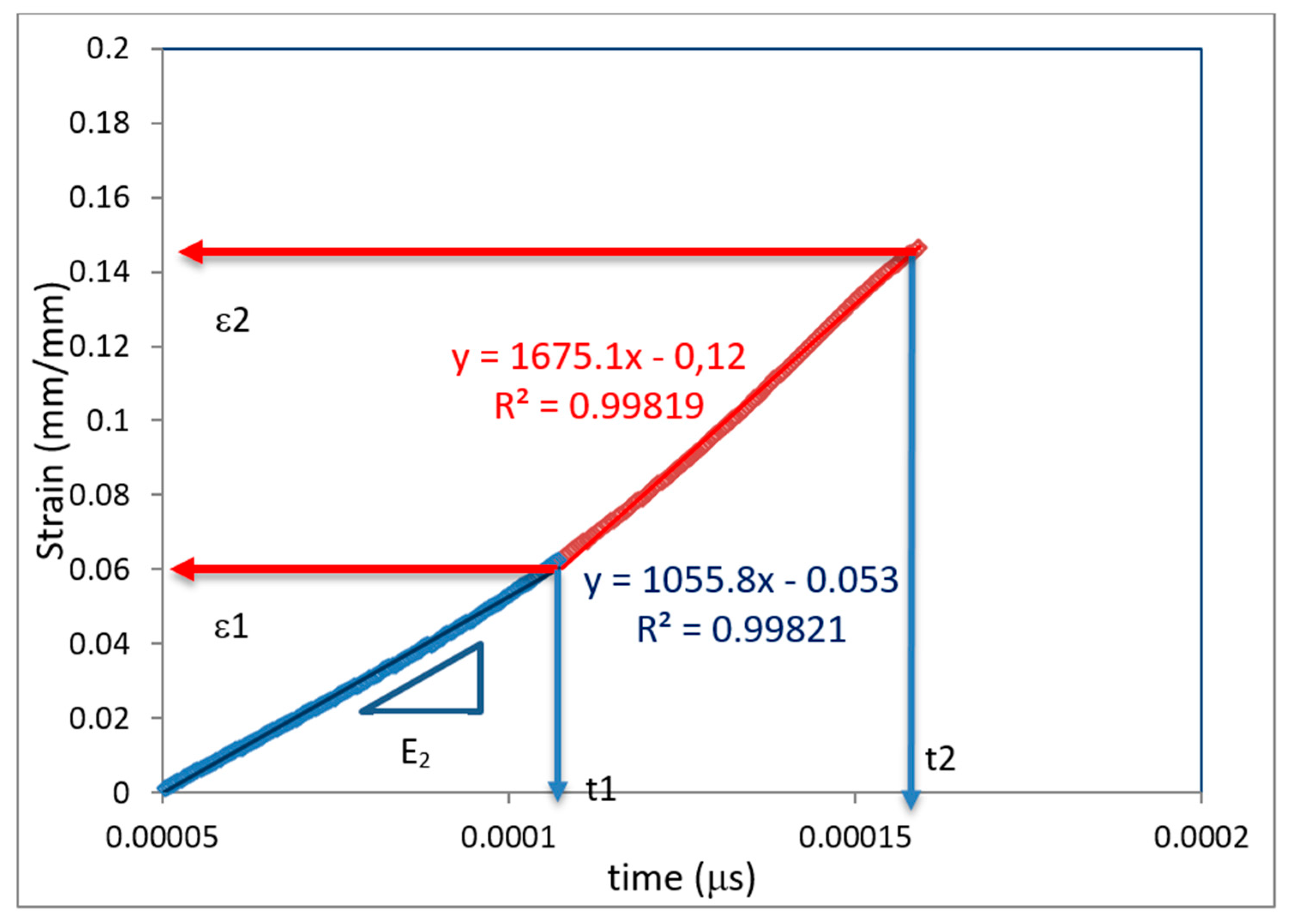
| t1 (μs) | 0.0001074 |
| t2 (μs) | 0.0001594 |
| ε1 (mm/mm) | 0.06271 |
| ε2 (mm/mm) | 0.14692 |
| R1 (1/s) | 1055.81956 |
| R2 (1/s) | 1675.09431 |
| Max. Strain Rate (1/s) | 1875 |
© 2020 by the authors. Licensee MDPI, Basel, Switzerland. This article is an open access article distributed under the terms and conditions of the Creative Commons Attribution (CC BY) license (http://creativecommons.org/licenses/by/4.0/).
Share and Cite
Baş, G.S.; Sancaktar, E. Mechanical Behavior of Toughened Epoxy Structural Adhesives for Impact Applications. ChemEngineering 2020, 4, 38. https://doi.org/10.3390/chemengineering4020038
Baş GS, Sancaktar E. Mechanical Behavior of Toughened Epoxy Structural Adhesives for Impact Applications. ChemEngineering. 2020; 4(2):38. https://doi.org/10.3390/chemengineering4020038
Chicago/Turabian StyleBaş, Gamze S., and Erol Sancaktar. 2020. "Mechanical Behavior of Toughened Epoxy Structural Adhesives for Impact Applications" ChemEngineering 4, no. 2: 38. https://doi.org/10.3390/chemengineering4020038
APA StyleBaş, G. S., & Sancaktar, E. (2020). Mechanical Behavior of Toughened Epoxy Structural Adhesives for Impact Applications. ChemEngineering, 4(2), 38. https://doi.org/10.3390/chemengineering4020038


