A significant amount of human-made CO
2 emissions has its origin in combustion processes such as the burning of coal, oil and gas [
1]. CO
2 capture utilization and storage (CCUS) has been suggested to cope with such emissions as a possible solution. The term CCUS describes a process that involves the capture of CO
2 from extensive facilities that are burning fossil- or biomass fuel. The captured CO
2 can be used at the facility or compressed and stored in permanent storage locations. Such locations for storage can, for instance, be depleted oil and gas reservoirs. Approximately 230 Mt of CO
2 is utilized globally each year, largely for fertilizer production (roughly 125 Mt/year) and improved oil recovery (around 70–80 Mt/year). Food and beverage manufacturing, cooling, water treatment, and greenhouses are some of the other commercial uses of CO
2. Today, 20% of the global CO
2 emissions are emitted from heavy industries, and the world’s carbon-capture facilities can capture more than 40 Mt of CO
2 [
2]. This amount of captured CO
2 is expected to double because the interest in CO
2 capture is growing. More facilities for CO
2 capture are being built, and the technology is recognized as a significant contributor to reducing CO
2 emissions [
2].
1.1. Literature Review
Post-combustion CO
2 capture is the most industry-established capture method found in fossil fuel power plants and, to some extent, in the cement, steel, and iron industries [
4]. Regarding a study by Patel et al. [
5], CO
2 capture is the most expensive part of the overall carbon-capture and storage (CCS) operation, accounting for about 70% of the total cost [
5]. A lot of work has been done on the simulation and cost optimization of CO
2 capture. The work in this study is a continuation of previous projects at the University of South-Eastern Norway on CO
2 capture simulation and cost estimation using Aspen HYSYS. Therefore, it is interesting to investigate which variables affect the plant cost.
According to Kallevik [
6], the cost of a plant is mostly influenced by five factors. The first is the exhaust gas flow that goes into the absorption column. This affects the dimensions of the process equipment in the gas path, which is a large part of the total equipment. The second is the CO
2 content in the flue gas. A high concentration lowers the energy consumption due to a higher driving force. Third, an increase in CO
2 removal rate increases energy consumption. Fourth, the flow rate of the solvent determines the size of the equipment and the utility need. Fifth is the energy requirement of hot utility and electricity. A hot utility is required as the desorption is endothermic, and it needs heat to reverse the CO
2 absorption. The thermal energy need will increase with a high solvent flow rate. The electricity demand is mainly due to the flue gas transport through the process and will grow with the pressure requirement and volume flow.
Lars Erik Øi [
7] used Aspen HYSYS to simulate a basic combined cycle gas power plant and a monoethanolamine (MEA)-based CO
2 removal process. The CO
2 removal (%) and energy consumption in the CO
2 removal plant were calculated as a function of amine circulation rate, absorption column height, absorption temperature, and steam temperature. The focus has been on MEA-based absorption and desorption calculation techniques for CO
2 collection of atmospheric exhaust gas of a gas-based power plant in Aspen HYSYS. Total CO
2 removal quality and heat consumption have been calculated as a function of circulation rate, absorber temperature, and other variables. One of the project’s objectives was to determine the process’ cost optimum parameters [
7].
Rubin et al. [
8] advocated using a uniform set of items to include in a cost estimate, a standard nomenclature to characterize each cost element, and a consistent technique of aggregating intermediate cost elements to arrive at a project’s total capital and operational costs. To increase the clarity and uniformity of cost estimates for greenhouse gas mitigation methods, they propose a standard costing approach as well as standards for CCS cost reporting [
8]. Van Der Spek et al. [
9] studied the recent advances in CCS engineering and economic analysis in 2019. They evaluated equipment design and size, cost indices and location factors, process and project contingency costs, CO
2 transportation and storage costs, and uncertainty analysis and validation.
Xiaobo Luo, in his PhD thesis [
10], provided modelling, simulation, and optimization research on the best design and operation of an MEA-based post-combustion carbon-capture (PCC) process and integrated system with a natural gas combined cycle (NGCC) power plant, with the goal of lowering the cost of PCC commercial deployment for NGCC power plants. He created a cost model, using vendor-provided key equipment costs from a benchmark report that included a comprehensive technical design [
10].
In another study, Øi et al. [
11] simulated several absorption and desorption configurations for 85 per cent amine-based CO
2 removal from a natural gas-fired power plant. Simulated processes include a standard procedure, split-stream, vapor recompression, and various combinations thereof. Equipment dimensioning, cost estimates, and process optimization have all been carried out via the simulations. A basic vapor recompression case was determined to be the most cost-effective arrangement of the analyzed cases [
11].
Aromada and Øi indicate in their research [
3] that both vapor recompression and vapor recompression paired with split-stream operations can minimize energy usage. Among the combinations studied, the vapor recompression technique was shown to be the most energy efficient. In addition, for the CO
2 capture parameters, which are based on a natural gas-based power plant project in Mongstad, Norway, energy optimization and economic analysis were undertaken [
3].
Regarding the other methods of CO
2 removal, Roussanaly et al. [
12] present a new systematic method for designing and optimizing CO
2 capture membrane systems that integrates both technological and economic principles. This approach generates graphical separation issue solutions in order to construct a cost-optimal membrane system that meets CO
2 capture ratio and purity standards. The technique is demonstrated through the design of a post-combustion CO
2 capture membrane system placed on an Advanced Super Critical (ASC) power station and compared to a MEA capture unit. Finally, a comparison is made between the cost model used and models found in the literature to show that the competitiveness of the membrane system described in this research is attributable to superior design rather than an underestimating of the membrane capture cost [
12].
CO
2 capture science and technology based on adsorbents are discussed and reviewed in terms of chemistry and methodology by Patel et al. [
5]. Six criteria are anticipated to be satisfied in a successful sorbent design: cost, capacity, selectivity, stability, recyclability, and fast kinetics [
5].
To cost-optimize the plant, this study wishes to conduct a sensitivity analysis on the effect of the overall cost when process parameters are changed. The typical choices of process parameters are according to Øi [
7]: the gas temperature into the absorber, the pressure into the absorber, the minimum temperature difference in the lean/rich heat exchanger, the reboiler temperature, the condenser temperature or the reflux ratio, the solvent circulation rate, the pressure in the desorber, and efficiency of the CO
2 removal rate of the process. The process parameters investigated are the efficiency of the absorber, the minimum temperature in the lean/rich heat exchanger, and the absorber packing height.
For efficiency, similar studies were conducted by Øi et al., [
13], Kallevik [
6], and Ali [
14]. They all ended up with an optimum cleaning efficiency equal to 85%. Ali found an optimum efficiency of 87%.
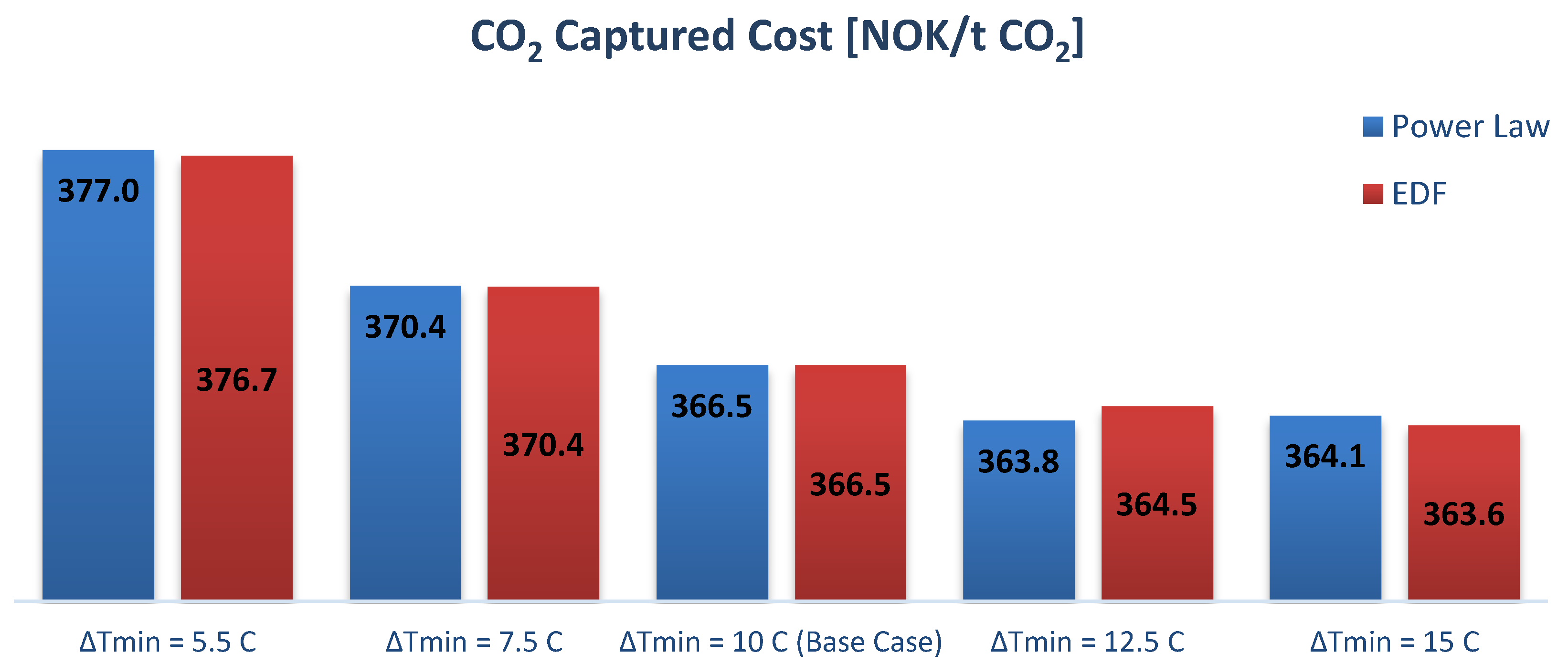
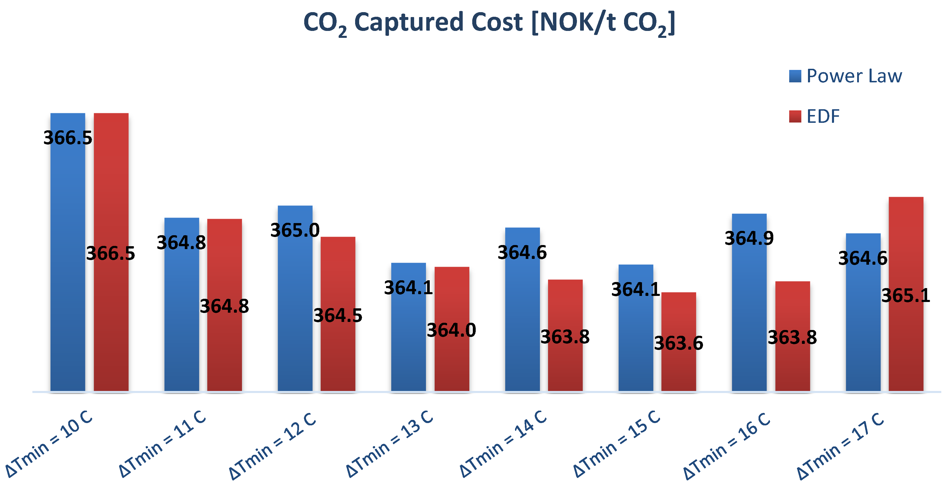
For the minimum temperature (ΔT
min) in the lean/rich heat exchanger, Aromada et al. [
15] calculated 15 °C as the optimum. However, Kallevik [
6] and Øi et al. [
13] found ΔT
min = 13 °C as the optimum. It is worth noticing that in Øi et al. [
13], depending on the parameters, the optimal temperature difference in the primary heat exchanger was determined to be 10–15 °C, which also agrees with the result of Aromada et al. [
15].
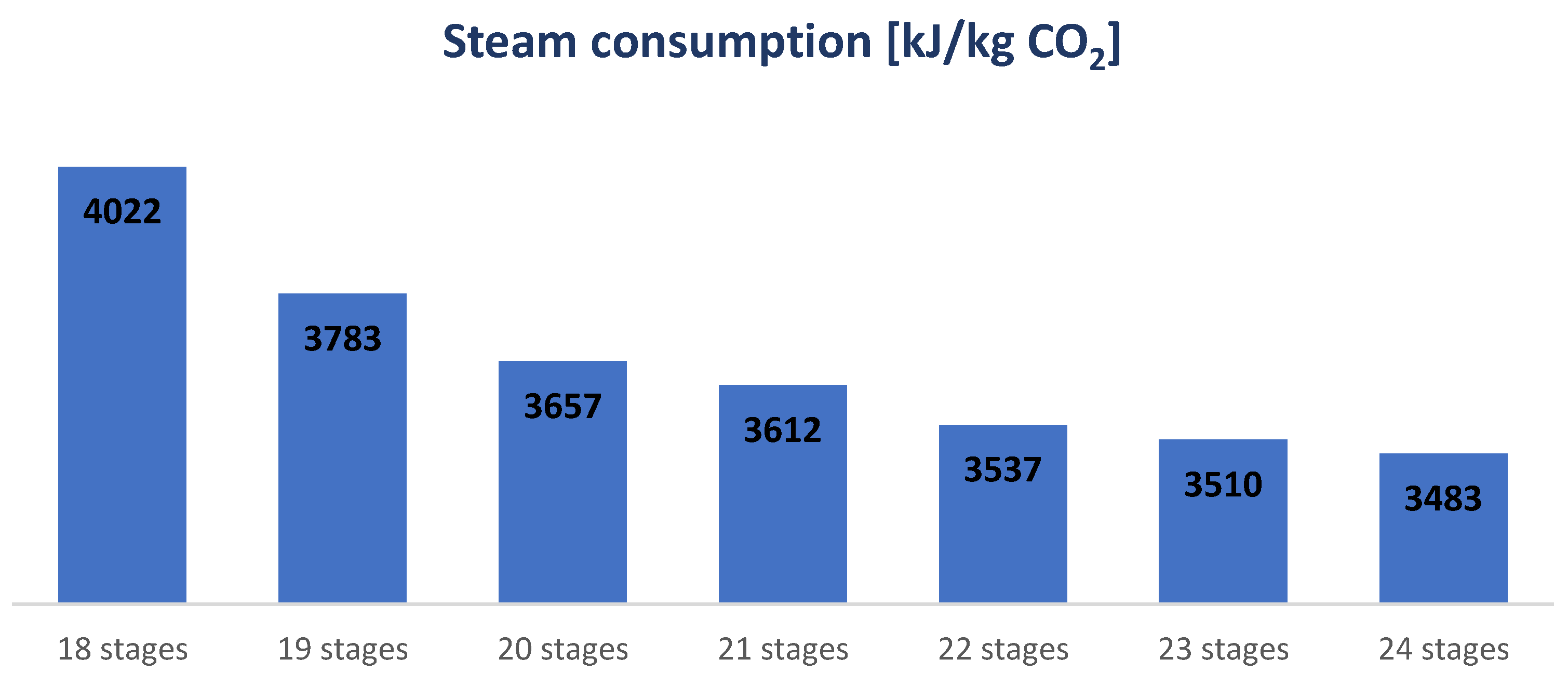
For the absorber packing height, Kallevik [
6] performed a sensitivity analysis with 90% cleaning efficiency, with a flue gas inlet 3.7 mole% CO
2 and an optimum absorber packing height of 19 m. Additionally, Øi et al. [
13] studied a 90% cleaning efficiency with a CO
2-content of 17.8 mole%. They ended up with an optimum packing height of 12 m.
1.2. Scope of the Study
This paper will investigate an amine absorption process based on available emission data from Fortum’s FEED report [
16]. There are no simulated and cost-estimated scenarios on CO
2 capture from waste incineration facilities reported. Fortum’s waste-burning facility at Klemetsrud in Norway has started a carbon-capture pilot project based on amine absorption of CO
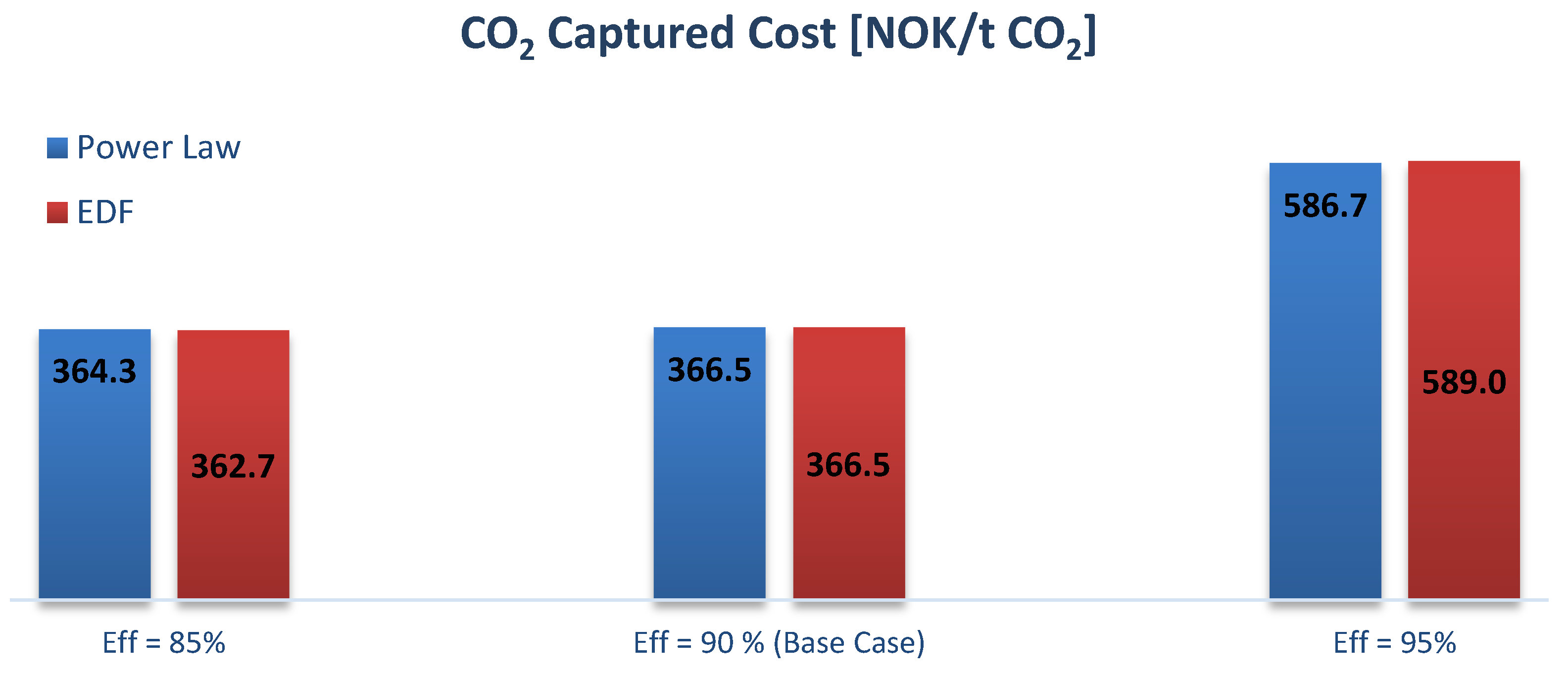
2. According to Fortum’s FEED report from 2019, the carbon-capture process targets removal efficiency of 95% of the CO
2 emissions [
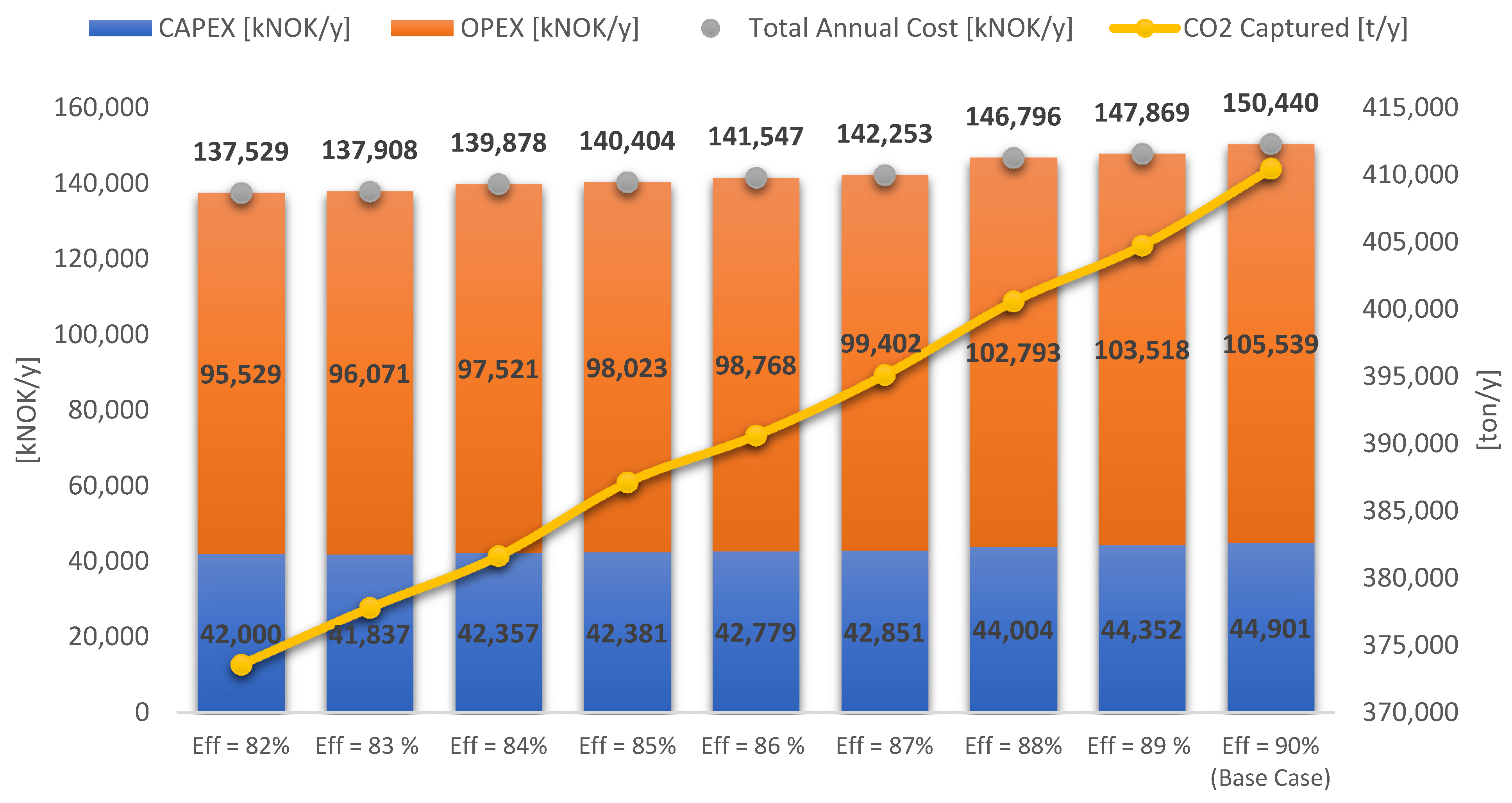
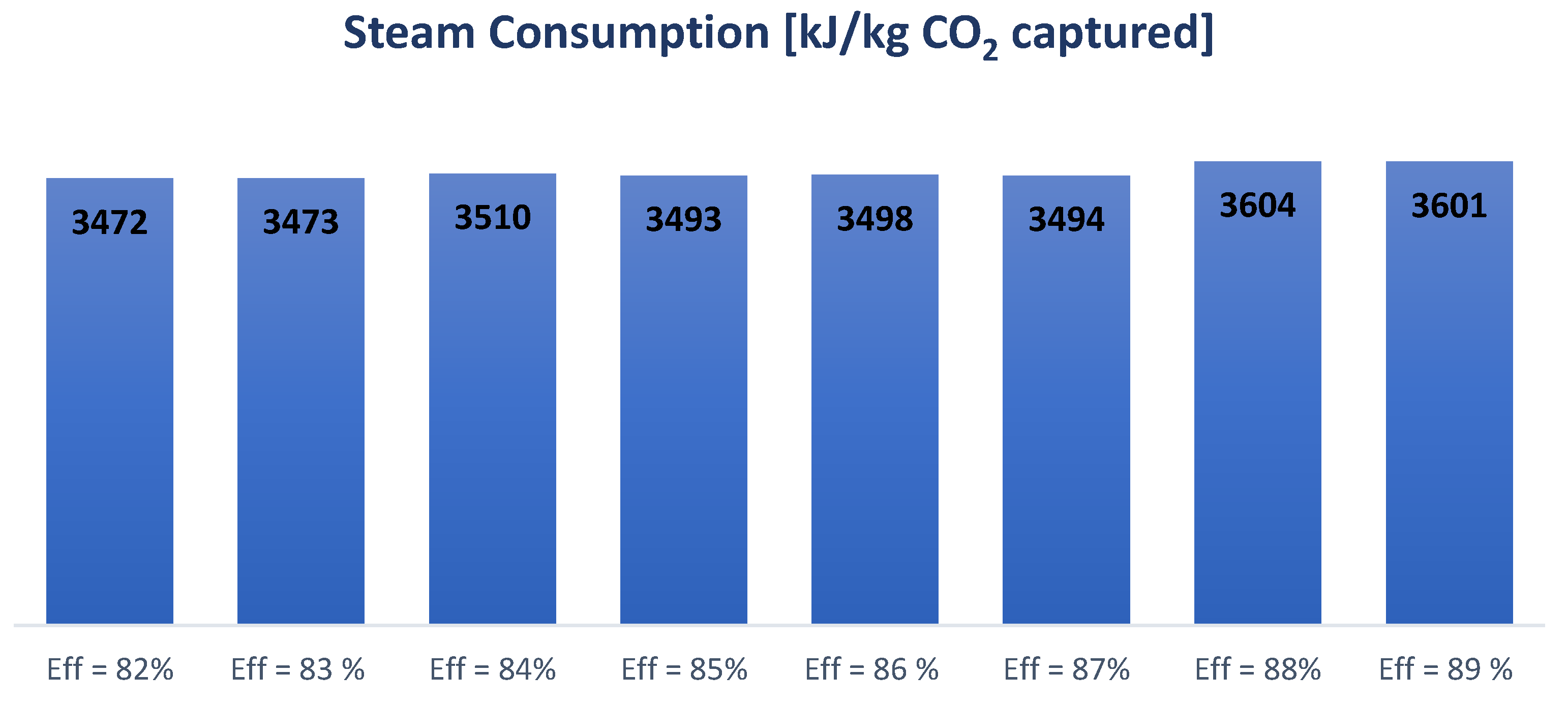
16]. A base case is established in Aspen HYSYS based on Fortum’s data, and then a dimensioning and cost estimation is performed. A sensitivity analysis executes cost optimization to minimize and reduce costs. A series of case studies conducts the technique to investigate the changes in price affected by the different variables. In this study, the variables manipulated are the absorber packing height, the CO
2 capture efficiency, and the lean/rich heat exchanger minimum temperature difference.
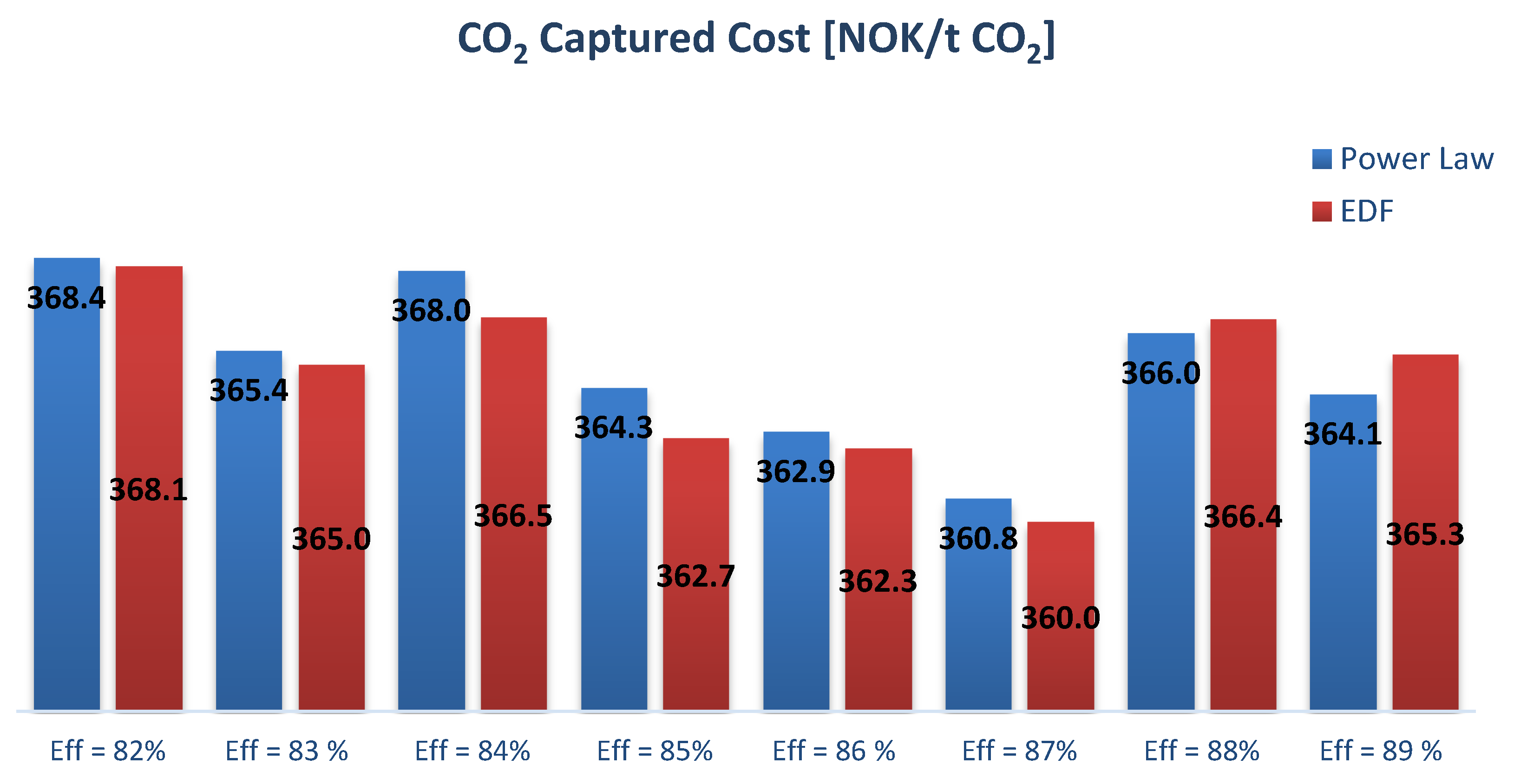
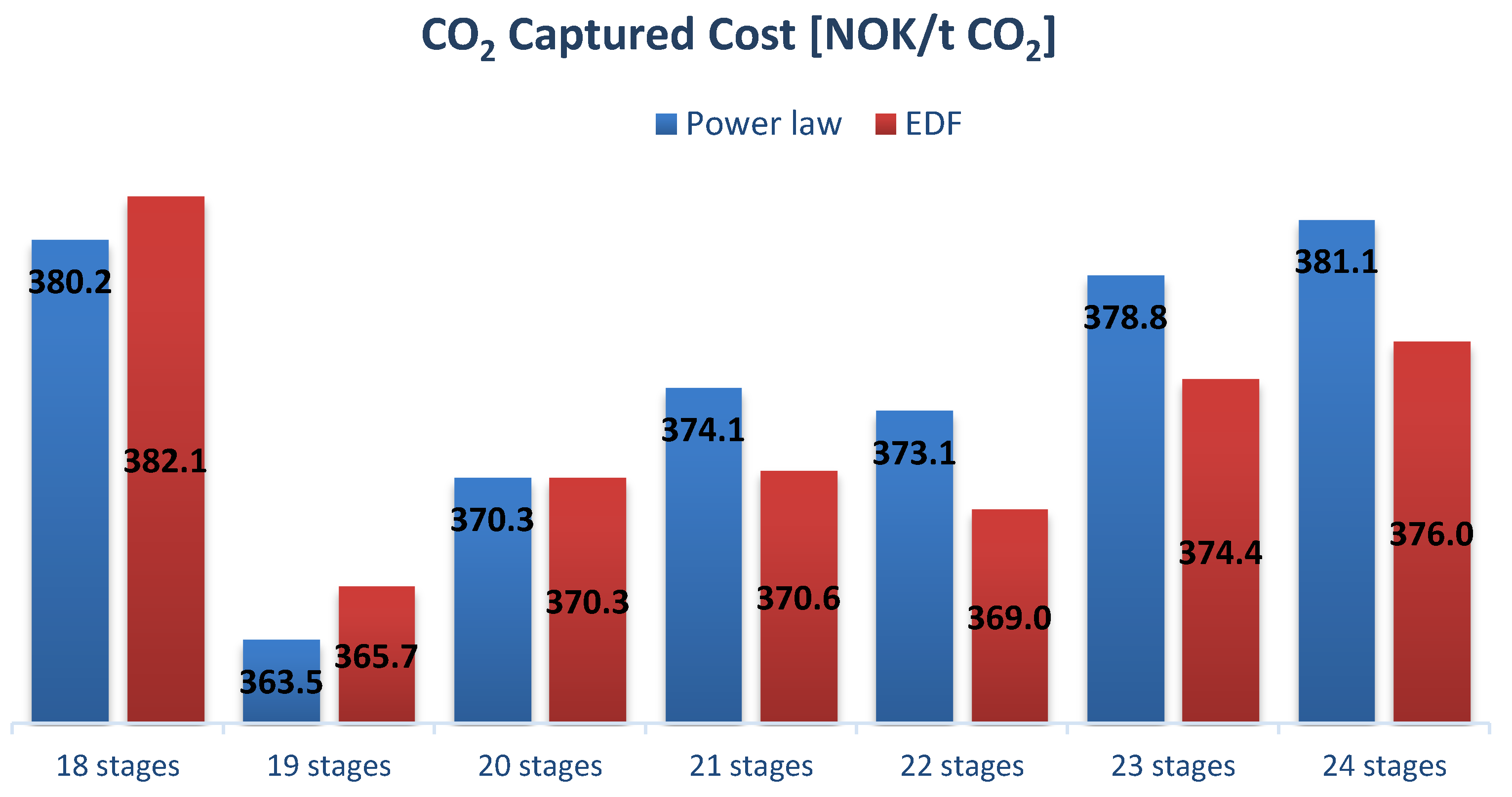
Further, the Power Law method is utilized to adjust the equipment cost when the sensitivity analysis changes the size. However, this way of calculating the equipment cost can be considered a “shortcut” as it is a time-saving process. To investigate the uncertainties in the results from the Power Law method, a comparison between the Enhanced Detailed Factor (EDF) using Aspen In-Plant Cost estimator and the Power Law method has been accomplished.
Lastly, to improve the usage of the Power Law method, a derivation of the individual size factor exponent for all the equipment—except the absorber and desorber—was executed. The derivation is a technique to find a unique exponent factor for each piece of equipment.
In this study, data from Fortum’s waste burning facility at Klemetsrud in Norway has been used. There are no simulated and cost-estimated scenarios on CO2 capture from waste incineration facilities reported in the open literature. Additionally, for all cases in the sensitivity analysis, a comparison between the Enhanced Detailed Factor (EDF) using Aspen In-Plant Cost estimator and the Power Law method has been accomplished to investigate the uncertainties in the results from the Power Law approach. In most literature, just the Power Law method has been utilized to adjust the equipment cost when the sensitivity analysis changes the size. Further, to improve the usage of the Power Law method, a derivation of the individual size factor exponent for all the equipment—except the absorber and desorber—was executed.


