Article

Experimental Study and Numerical Simulation of Hydrodynamic Parameters of Tangential Swirlers

by
Nikolai A. Voinov
,
Alexander S. Frolov
,
Anastasiya V. Bogatkova
and
Denis A. Zemtsov
*
Institute of Chemical Technology, Reshetnev Siberian State University of Science and Technology, 31 Krasnoyarsky Rabochy Av., Krasnoyarsk 660037, Russia
*
Author to whom correspondence should be addressed.
ChemEngineering 2022, 6(4), 48; https://doi.org/10.3390/chemengineering6040048
Submission received: 16 May 2022 / Revised: 22 June 2022 / Accepted: 23 June 2022 / Published: 27 June 2022
(This article belongs to the Special Issue Feature Papers in Chemical Engineering)

Abstract

:
This paper presents and patents new profiled- and annular-channel tangential swirlers with 1.8–3 times less hydraulic drag coefficient compared to swirlers with straight channel walls at the same flow rate, respectively. The results of numerical simulation of the gas velocity and pressure profiles for tangential swirler channels of different structures are presented. The modelling was carried out with the help of OpenFOAM software using the k-ε turbulence model. It is found that the shape of the velocity profile at the channel inlet has a decisive influence on the swirler drag coefficient. The greatest contribution to the total drag coefficient of the tangential swirler is made by the pressure drop at the channel inlet compared to the pressure drop at the channel wall and the channel outlet. The experimental dependencies of the tangential swirlers’ drag coefficient on the Reynolds number with a gas criterion of 2000–20,000 and the following structural channel parameters: width 1, 2–9 mm, height 1, 5–10 mm, number 5–45 units, inclination angle 0–45° are presented. The experimental data were compared with the modelling calculations and the convergence of data was achieved. The generalized dependence for the measurement of the hydraulic drag coefficient of three types of tangential swirlers considering the effect made by the geometric parameters (flow rate, width and height of the channel, wall inclination angle) on the pressure drop has been determined; it can be useful at the unit design stage as it allows for reducing the calculation time of the swirler parameters.

1. Introduction

The widespread use of swirling gas and liquid flows is due to the achievement of a significantly intensified transfer of momentum, heat, and mass in various devices compared to the well-known phase interaction methods.
The use of vortex swirling flows brought significant success in the chemical and oil processing industries, as well as in the energy industry and the gas emission filtering technologies.
Vortex flows are now widely used in gas turbines and combustors [1], centrifugal contactors [2], and circulating water cooling systems and cooling towers [3].
The swirling compacted layer can be used to intensify multiphase reactions [4,5], for absorption and desorption [6,7,8,9], and for gas emission purification [10,11].
Swirler devices designed to create a rotational motion in gas (steam) are used in separators to separate gas from droplets and dispersed particles [12,13,14], scrubbers for cleaning gas emissions, in contact stages and distillation column devices, in vaporizers, and in evaporators [15].
The integration of swirlers improves the technical and economic performance of the equipment for better compliance with the production technology requirements.
In this way, the practice shows that swirlers are promising devices and, therefore, the improvement of their structural options is a relevant task.
The main requirement for the swirler structure development is to create a device with a low hydraulic drag, intense flow swirling, and a high liquid or gas throughput, which are the parameters subject to various restrictions. For instance, when separators with vortex contact devices for droplet or particle settling are installed on a technological line, a restriction is applied to the resistance value of the unit, which causes the losses of fan or compressor productivity when exceeded. That is unacceptable and requires searching for constructive solutions to reduce the drag value with the maintained intense swirling that ensures the required effectiveness.
Reducing the swirler drag in the vortex scrubber design allows the gas transportation expenses to be reduced and to, therefore, reduce the operating costs. Installed on the rectification column trays, vortex contact devices with a low resistance value can reduce the steam consumption costs. Moreover, they maintain the required tray operation mode by varying the ratio of the constructive swirler parameters. The gas bubbles in the liquid are intensively crushed, and the liquid fluctuation on the tray deck and formation of stagnant zones are prevented.
Further improvement in vortex devices is impeded by the absence of reliable recommendations on the calculation of the swirlers’ parameters and making comprehensive analysis of their structures.
The dependencies known and used in engineering practice for the hydraulic drag measurement produce inaccurate and controversial results. For instance, the widely spread method of measuring the channel inlet and outlet pressure drop based on their section area ratio (swirling parameter) does not consider the flow hydrodynamics, causing undue errors. The data on the effect made by the channel width and slope angle on the drag value are controversial. There are no data on the effect made by the number and height of the channels on the pressure drop varying within a broad interval depending on the technological purpose of the unit.
The diversity of factors influencing swirler resistance makes it impossible to assess the degree of impact of each of them separately, as this requires computing power and a numerical model describing the gas behavior within the device [16,17,18,19,20,21,22].
The objective of this study is the experimental and numerical investigation of the hydrodynamic properties of tangential swirlers to identify the parameters and functional dependences for the subsequent calculation of the hydraulic resistance coefficient value.

2. Materials and Methods

The most commonly used swirlers are tangential (radial) swirlers for ensuring intensive flow swirling with a relatively simple design (see Figure 1).
As shown in Figure 1a, gas is fed through the gas feeding pipe 2, passes through the tangential channels 4, where it loses a part of its energy, then initiates the rotation and gains speed until it disperses, for instance, into a liquid placed on the mass transfer apparatus tray.
Tangential swirlers can be divided according to their design into devices with straight, profiled, and annular channel walls. The designs have different cross sections and curvatures of the channel wall sides.
Swirlers with straight channel walls are simple in design and, therefore, the most commonly used type. However, as the channel width and wall slope angle increase, the tangential component of velocity providing intensive flow swirling begins to decrease.
Swirlers with profiled channel walls [23,24] in some cases eliminate the above drawback and contribute to intense flow swirling with a relatively simple device design.
The next stage in improving swirler design was creating devices with annular channels. These have a high gas and liquid capacity and low resistance.
The complexity of calculating the hydrodynamic parameters of the swirlers [16,17] complicates their efficient practical use and requires comprehensive research.
The following equation was obtained for calculating the pressure drop in the swirler [25], taking into account friction and inertia:
E u = B · 3 · φ · ρ g l · 1 l + 1 8 · ψ · ( 1 φ ) · h + 2 · d ¯ · ρ g + u ¯ 2 · ρ g l · ( 1 l + 2 ) 2 · ρ g + I 4 · sin α 2 ,
where Eu = ΔP/ ( ρ g · u 2 ) —Euler’s criterion; ρ g l —gas-liquid layer density (kg/m3); I, B—swirler design-dependent factors; φ—gas content; ρ g —gas density (kg/m3); ψ—minimum relative area (m); h+—device dimensionless height; d ¯ —bubble dimensionless diameter; l+—dimensionless distance from axis to layer boundary; and u ¯ —average gas flow velocity (m/s).
The dependence shows the variety of swirler parameters affecting its resistance.
The tangential swirler resistance coefficient can be calculated using the presented empirical dependences [26,27].
For example, the paper [26] presents the dependence as
ξ = exp ( 4.23 2.345 · A ) ,
where A = f/F—rotation factor; f = n∙h∙b—total channel area (m2); F = π∙Dsh—swirler area (m); b—channel width (m); h—channel height (m); Ds—swirler diameter (m); and n—number of channels.
Dependence (2) does not take into account the influence of the design parameters on the resistance or flow hydrodynamics.
The expression formulated as an empirical dependence is known [28]:
ξ = 3.1 · α 0.7 · ( b h ) 1.54 · ( h D s t ) 1.48 ,
where α—channel slope angle (degrees); b, h—width and height of channel walls (m); and Dst—stage diameter (m).
Equation (3) contradicts the dependence presented in paper [27]:
ξ = 21 · R e 0.28 · ( h b ) 0.25 ,
where Re—Reynolds number; h—swirler channel height (m); and b—swirler channel width (m).
The results of calculating the drag coefficient according to these equations, depending on the design of the swirler, may differ by two or more times.
According to [26,27,29], the resistance of a tangential device depends on the rotation factor, swirler radius, number of channels, their width and height, and channel wall thickness and slope angles [27].
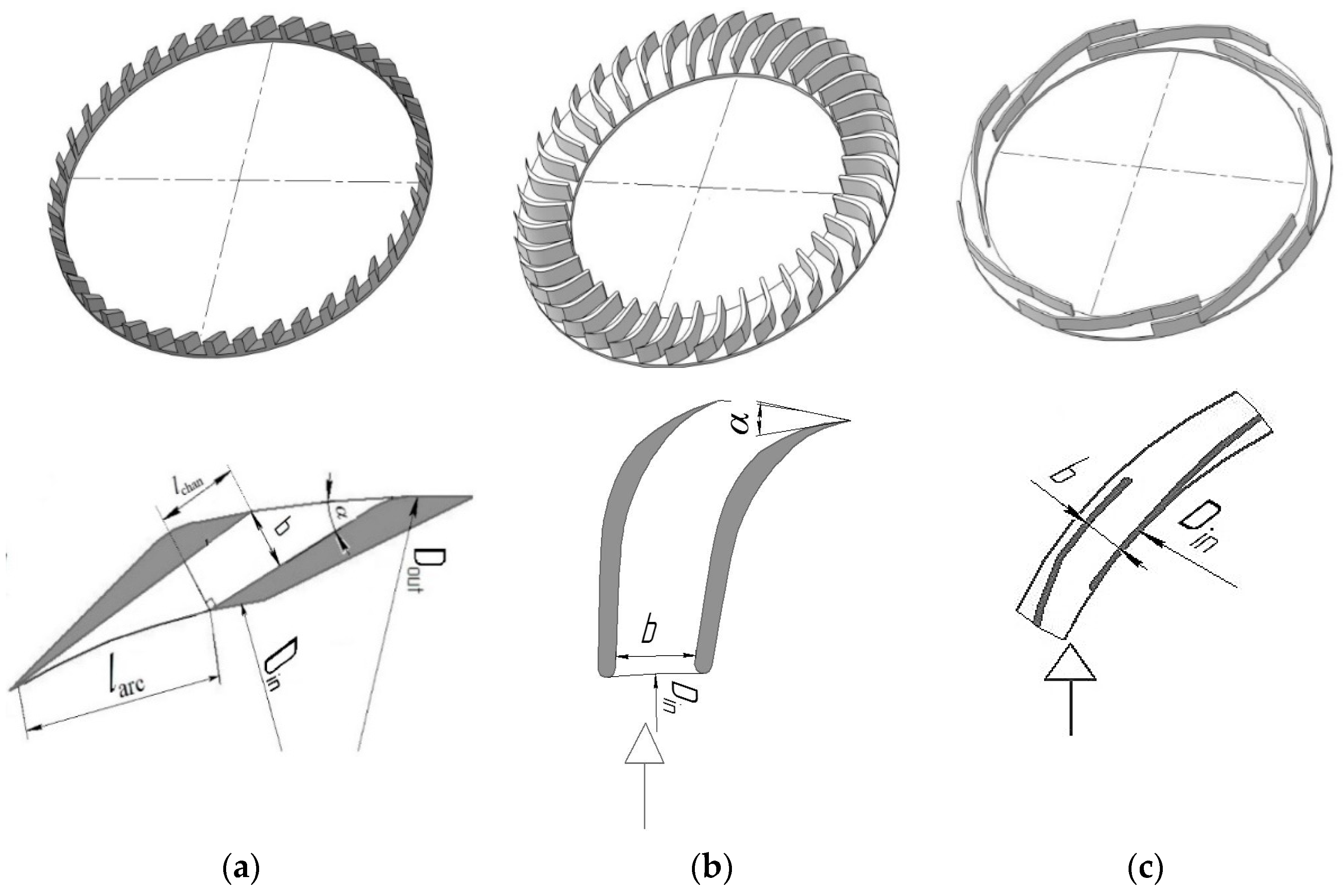
The swirlers were designed based on a 3D model on a computer numerical control (CNC) machine using layer-by-layer printing technology. The studied swirler models are presented in Figure 2, and their parameters are described in Table 1.
The swirlers were blown through with air at a temperature of 25 °C, with the orifice-measured air consumption being up to 100 m3/h.
The following dependence was used to determine the experimental value of the swirler resistance coefficient:
ξ = 2 · Δ P ρ g · u ¯ 2 ,
where ΔP is the pressure drop (Pa), ρ g is the gas density (kg/m3), and u ¯ is the average gas flow velocity (m/s).
The average gas flow velocity was calculated from the smallest section of the swirler channel.
The design resistance coefficient was determined according to expression (5) based on the design pressure drop determined by numerical simulation.
The Reynolds number was determined from the dependence:
R e = u ¯ · b · ρ g μ ,
where b—channel width (m), μ—dynamic viscosity coefficient (Pa s), and Re—Reynolds number.
The hydrodynamic properties of the swirler, velocity fields, and pressure drops were studied by numerical simulation using OpenFOAM software—an interactive medium that is based on the control volume method [30].
Initially, to prepare the swirler for hydrodynamic analysis, solid-state models (Figure 3) of its interior were created to reproduce its internal working cavity and all the curves of the actual device. The reproduced geometry was imported to OpenFOAM software and broken into computational grid elements.
The embedded utilities were used to make up a computational grid with a significant concentration of elements in the areas of the greatest velocity gradient. The velocity profile developed on the basis of the experimental consumption value was set up on the swirler model inlet; at the outlet, excessive pressure was adjusted. On all the other solid walls of the interior geometry cavity, the noSlip condition of sticking was chosen to ensure the velocity. The mesh independence test revealed an optimal computational grid consisting of 1,300,000 different-shaped elements. The optimal mesh means a reduction in the computational mesh in the most complex geometry areas with high velocity gradients and constant controlled parameter values (velocity, pressure) in the mesh convergence process.
In the simulation, air having physical and chemical properties corresponding to full-scale tests was set as a working medium. For the computation, the turbulent k-ε model commonly used in computational practice was selected. The model used showed good results in the internal flows. It works stably in the computation process, requiring no significant computational resources.
The modelling data presented herein correspond to the established working mode. The established working mode was found out to be achieved in 5 s.
The desired values were pressure drop and gas velocity. The total velocity up and its components along the coordinate axes ux, uz, and uy were calculated. In post-processing the numerical experiment results, the resulting pressure value P characterizes the total swirler losses ΔP.
The design pressure and channel inlet and outlet velocity in the simulation were read from lines Lin and Lout, Figure 3c,d, and when processing the obtained data in accordance with Figure 3a,b.
Pressure drop losses due to the inlet ΔPin were calculated as per Figure 3a,b as follows:
ΔPin = PPtran,
where P is the total design pressure in the swirler chamber (Pa); Ptran is the channel inlet pressure in the transition area channel.
Figure 3a,b presents a diagram for calculating the pressure drop in a preset swirler section. The design pressure and velocity (at the channel inlet and outlet) during simulation and data processing were read along the L lines, Figure 3c,d.

3. Results and Discussion

3.1. Swirler Resistance Comparison

Figure 4 presents the changes in the resistance coefficient dependent on the Reynolds number for the swirlers with straight, profiled, and annular channels for similar parameters. According to the actual data, the smallest pressure drop was found in the swirler with annular channels (Figure 4a, points 3), and the largest was found in the device with straight channel walls (Figure 4a, points 1). The simulation results showed that the greatest impact on the swirler pressure drop value is made by the head loss caused by the forces of viscous friction against the channel walls and head loss at the channel inlet (Figure 4b). According to these data, the inlet loss of a swirler with annular channels is 2.4 times less compared to channels with straight walls and 1.4 times less than profiled walls. The outlet pressure losses for all three compared types of swirlers are comparable.
It can be assumed that the lowest resistance of the annular swirler is due to the presence of one leading edge at the gas inlet to the channel, as opposed to channels with straight and profiled walls, as well as the difference in the gas velocity profile in each device.
The resistance of a profiled channel has a lower pressure drop than straight channels due to the difference in the slope of walls at the channel gas inlet. The slope angle in the channel with straight walls was 26° and in the profiled channels, 90°.

3.2. Gas Flow Modes in Swirler Channels

Experimental values of the resistance coefficient of the tangential swirlers having different channel profiles and widths depending on the Reynolds number presented in Figure 5 allowed two typical gas flow areas to be identified: the turbulent and self-pressing flows separated by a dashed line.
For the straight channels, Figure 5a, the critical Reynolds number characterizing a transfer to the self-pressing mode was Re = 6000–7000, with the resistance coefficient having the dependence ξ = Re−0.265. For the profiled channels, Figure 5b, Re = 6500–8000, and ξRe−0.297, and for the annular channels Re = 8000–10,000, Figure 5c, and ξRe−0.396.
For all the studied channel types, increasing width leads to a corresponding increase in the hydraulic resistance.

3.3. Effect of Channel Length on Swirler Resistance

The experimental resistance coefficient value measured at a different swirler channel length with straight and annular walls obeys the dependence ξ = lchan0.19, Figure 6. The pressure drop is caused by the viscous friction forces acting on the channel wall. This paper focused on swirlers having hydraulically smooth channel walls, which was also considered in the boundary conditions of the numerical model.

3.4. Influence of the Channel Wall Slope Angle on Swirler Resistance

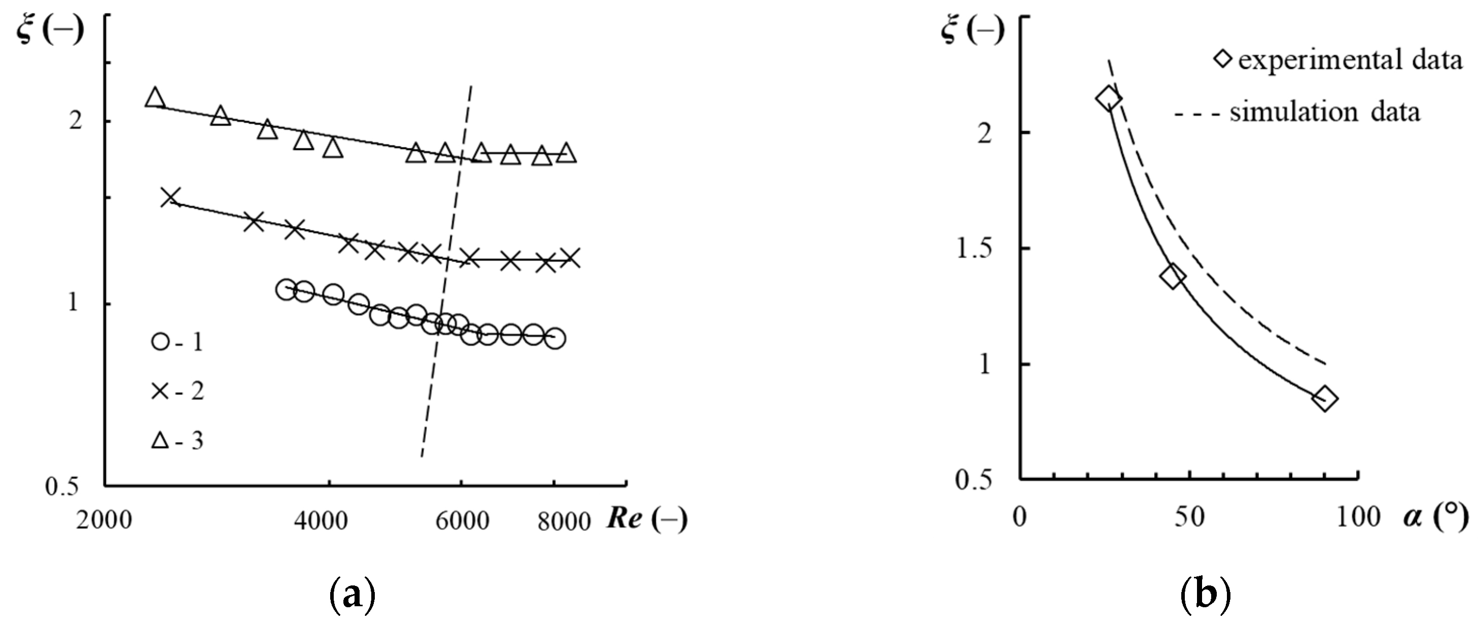
The values of the resistance coefficient of the swirler having straight channel walls at different slope angles are presented in Figure 7. An increase in the slope angle of the straight channel walls from 26° to 90° leads to a two-fold decrease in the experimental resistance coefficient (see Figure 7b), which is confirmed by numerical simulation. The computation results are presented with the dashed line in Figure 7b. The resistance coefficient values obey the dependence ξ = α−0.71.
Figure 8 presents the total gas velocity profiles at the channel inlet and outlet at different channel wall slope angles.
With a change in the channel wall slope angle, the gas velocity profiles at the channel outlet do not change significantly. With a change in the channel wall slope angle, the velocity distribution at the channel inlet changes. As the channel wall slope angle decreases, the velocity profile tends to be concave, i.e., the velocity decreases along the length larc between the edges of adjacent channel walls. A decrease in velocity leads to an increase in pressure losses both at the inlet and in the channel itself compared to channels placed at an angle of 90°. As the velocity decreases, the dynamic velocity on the channel wall also decreases, leading to an increase in the boundary layer thickness and the resistance value.
With a change in the value of α from 26° to 45°, the experimental value of the resistance coefficient was reduced by 1.5 times, and by 1.9 times in the numerical simulation. The difference in the drag coefficient calculated with numerical modelling compared to the experimental one can be reduced by means of correction of the turbulence model factors used.
Figure 9 presents the distribution of the total velocity up and its components along the coordinate axes uz, uy, and ux. The velocities uy and ux are comparable and have bigger values than the velocity uz. At a channel slope angle of 26°, the velocities uy are higher than at a channel slope angle of 45°. That is, reducing the channel wall slope angle increases the flow rotation intensity.

3.5. Influence of Channel Height and Number on Resistance Value

Figure 10 presents the typical dependences of the velocity and pressure profiles at different swirler channel heights. As established for swirlers with straight and profiled channel walls, an increase in the wall height leads to a decrease in the pressure drop and obeys the dependence ξ = h−0.13.
According to the presented velocity curves, other things being equal, a swirler with a lower channel height has a lower velocity compared to swirlers with higher channels. It is safe to assume that viscous frictional forces on the swirler bottom and lid at a low channel height have a bigger impact on the velocity profile at the inlet. A decrease in velocity leads to an increase in the thickness of the boundary layer and an increase in the swirler head loss.
For annular channels, no relationship between the channel height and its resistance was revealed.
With a decrease in the number of channels in the swirler from 40 to 8, the swirler resistance decreased by 15%, which the numerical simulation confirmed. An analysis of the velocity profile revealed that for 8 channels, the outcoming gas flows do not contact each other, while for 40 channels, they mix, which, according to [31,32], generates more turbulence in the flow, and, therefore, increases the pressure drop.

3.6. Effect of Channel Width on Resistance

According to the simulation results, the dashed lines in Figure 11, and the experimental data shown as points in Figure 11, an increase in the channel width leads to an increase in the swirler resistance coefficient and obeys the dependence ξ~b0.6.
Figure 12 presents the shares of pressure drop (from total resistance) caused by channel inlet, walls, and outlet at different swirler channel widths. According to the data obtained, the largest contribution to the total resistance is made by the head loss in the channel and the inlet loss.
Velocity profiles obtained by simulation with different channel widths and the same Reynolds number are presented in Figure 13. According to the data obtained, an increase in the channel width leads to a decrease in the gas velocity which, in turn, leads to an increase in the swirler head losses. Due to the different velocity profiles at the channel inlet, the velocity is redistributed along the channel length, which affects the swirler resistance.
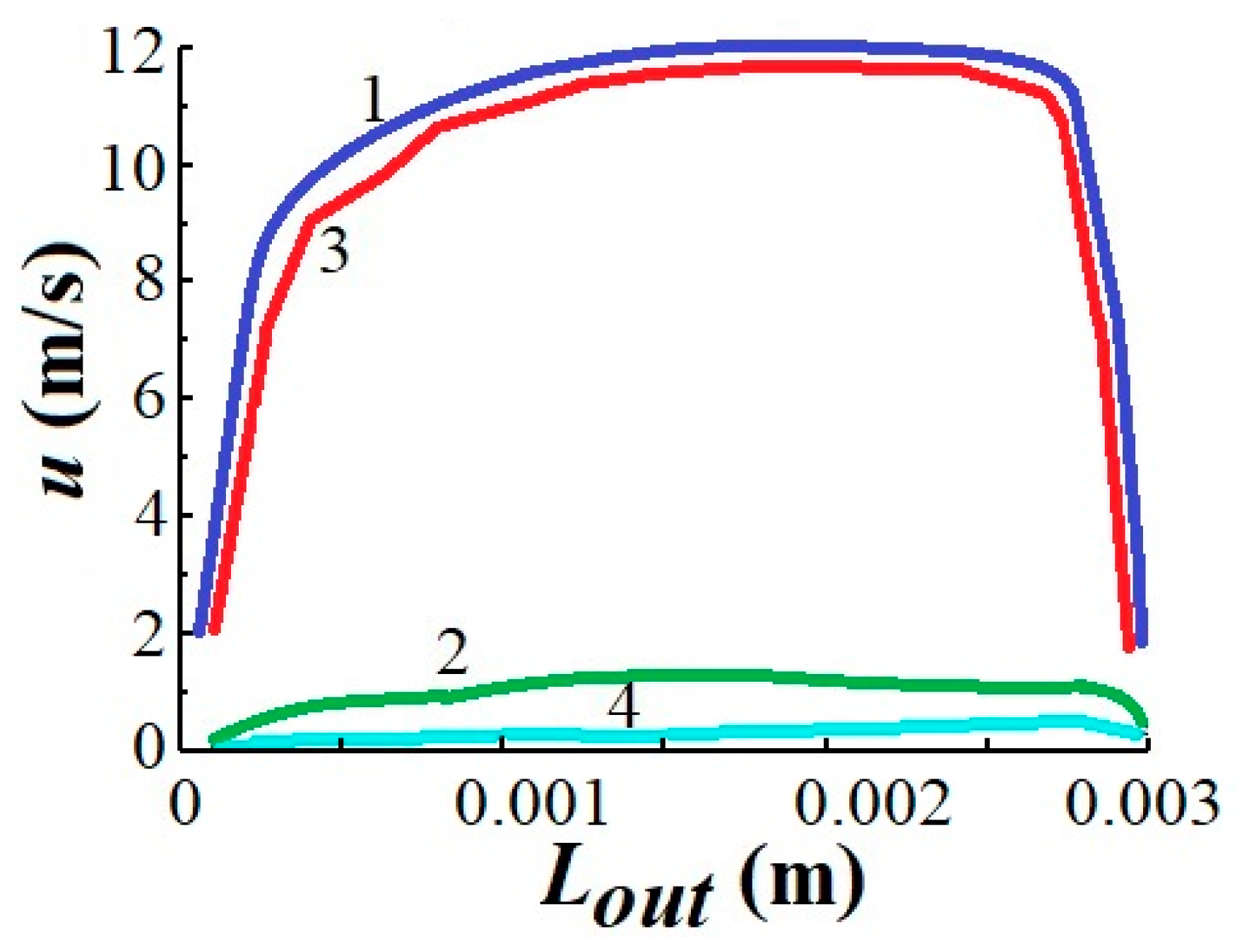
The distribution of the total velocity up and its components along the coordinate axes uy, ux, and uz for the annular channels are presented in Figure 14. The tangential component of the velocity uy has the biggest value compared to the velocities ux and uz and makes the main contribution to the total velocity value.
Compared to the straight channel walls, the tangential velocity component for the annular channels dominates the others.
The tangential velocity uy distribution curves in the annular channel, computed for different channel lengths, are presented in Figure 15. According to the collected data, the tangential velocity element increases along the annular channel length under 0.007 (m). For this reason, designing a further increase in the swirler channel length is not practical.

3.7. Dependence for Estimating the Resistance Coefficient

To calculate the hydraulic resistance of a swirler for developing experimental data- and numerical simulation-based designs, an empirical dependence was formulated. The experimental swirler resistance coefficient values were processed as presented in Figure 16.
ξ = K·α−0.71·Rem·lchan0.19·b0.6·hq,
where K = 10,173—coefficient for straight channels, K = 751—for profiled channels, K = 1571—for annular channels; m = 0.281 for straight and profiled channels, m = 0.396 for annular channels (Figure 4); m = 0.042 general in turbulent mode; q = 0.13 for straight and profiled channels, q = 0 for annular channels (Figure 11).

4. Conclusions

1. For the first time, comprehensive experimental studies of the effect made by the resistance of the tangential swirlers’ structural parameters with the results confirmed by numerical modelling data have been carried out. The shape of the velocity profile depends on both the gas flow rate and the channel design and was proved to be making the greatest impact on the total pressure drop due to the head loss conditioned by the channel inlet velocity profile shape.
2. The dependence for the computation of the tangential swirler hydraulic drag coefficient considering the flow rate and the channel size has been formulated. As the value of the Reynolds gas criterion increases, the drag coefficient decreases due to a reduction in the viscous friction force. Increasing the channel width and decreasing the inclination angle results in an increase in head loss due to a reduction in the gas velocity at the channel inlet. The height of the swirler channel influences the pressure drop by changing the velocity profile due to the gas friction against the cover and the bottom of the unit.
3. The completed research allowed us to achieve good convergence of the numerical simulation and experimental results and to draw conclusions on the rationality of using the given computation method. The new data obtained allow for the design of swirlers with a given drag coefficient within a wide range of design and process parameters, taking into account the flow hydrodynamics based on the analysis of velocity and pressure profiles.

Author Contributions

N.A.V. conceived and designed the experiments. A.S.F. performed numerical simulation of experiments. A.V.B. performed the majority of experiments and D.A.Z. performed additional experiments. All authors contributed to the data analysis and writing of the paper. All authors have read and agreed to the published version of the manuscript.

Funding

The work reported in the paper Experimental Study and Numerical Simulation of Hydrodynamic Parameters of Tangential Swirlers was supported by the Ministry of Science and Higher Education of the Russian Federation within the framework of the State Assignment of the Technology and Equipment for the Chemical Processing of Biomass of Plant Raw Materials project FEFE-2020 0016.

Data Availability Statement

This article contains all the data generated or evaluated throughout the research.

Conflicts of Interest

The authors declare no conflict of interest.

Abbreviations

Arotation factor
bwidth of the channel in the swirler (m)
Ddiameter (m)
d ¯ bubble dimensionless diameter
EuEuler’s criterion
Farea of the swirler (m2)
ftotal area of the channels (m2)
hheight of the channels in the swirler (m)
h+device dimensionless height
I, B, Kswirler design-dependent factors
Jshare of the head loss
Lline of pressure reading (m)
llength (m)
l+dimensionless distance from axis to layer boundary
m, qdegree
nnumber of channels (pcs)
Pdesign pressure (Pa)
ΔPpressure drop (Pa)
ReReynolds number of gas in the swirler’s channels
udesign gas velocity in the swirler’s channels (m/s)
u ¯ average gas flow velocity in the swirler’s channels (m/s)
αchannel slope angle (deg)
μcoefficient of dynamic viscosity of the gas (Pa·s)
ξdimensionless resistance coefficient
ρ density (kg/m3)
φdimensionless gas content
ψminimum relative area (m)
Indices
arcarc
chanchannel
ggas
g-lgas-liquid
ininlet
outouter
ptotal
sswirler
ststage
trantransition area
wworking
ytangential

References

  1. Eldrainy, Y.A.; Ibrahim, M.F.A.; Jaafar, M.N.M. Investigation of radial swirler effect on flow pattern inside a gas turbine combustor. Mod. Appl. Sci. 2009, 3, 21–31. [Google Scholar] [CrossRef] [Green Version]
  2. Sandilya, P.; Rao, D.P.; Sharma, A.; Biswas, G. Gas-Phase Mass Transfer in a Centrifugal Contactor. Ind. Eng. Chem. Res. 2001, 40, 384–392. [Google Scholar] [CrossRef]
  3. Dmitrieva, O.S.; Dmitriev, A.V.; Nikolaev, A.N. Distribution of circulating water in the work area of a vortex chamber with disk atomizer for the purpose of increasing the efficiency of the cooling process. Chem. Pet. Eng. 2014, 50, 169–175. [Google Scholar] [CrossRef]
  4. Wang, Z.; Yang, T.; Liu, Z.; Wang, S.; Gao, Y.; Wu, M. Mass Transfer in a Rotating Packed Bed: A Critical Review. Chem. Eng. Process. 2019, 139, 78–94. [Google Scholar] [CrossRef]
  5. Chen, Y.-S.; Lin, C.-C.; Liu, H.-S. Mass Transfer in a Rotating Packed Bed with Various Radii of the Bed. Ind. Eng. Chem. Res. 2005, 44, 7868–7875. [Google Scholar] [CrossRef]
  6. Sun, B.; Zou, H.; Chu, G.; Shao, L.; Zeng, Z.; Chen, J. Determination of Mass-Transfer Coefficient of CO2 in NH3 and CO2 Absorption by Materials Balance in a Rotating Packed Bed. Ind. Eng. Chem. Res. 2012, 51, 10949–10954. [Google Scholar] [CrossRef]
  7. Qian, Z.; Xu, L.; Cao, H.; Guo, K. Modeling Study on Absorption of CO2 by Aqueous Solutions of N-Methyldiethanolamine in Rotating Packed Bed. Ind. Eng. Chem. Res. 2009, 48, 9261–9267. [Google Scholar] [CrossRef]
  8. Chen, Q.-Y.; Chu, G.-W.; Luo, Y.; Sang, L.; Zhang, L.; Zou, H.-K.; Chen, J.-F. Polytetrafluoroethylene Wire Mesh Packing in a Rotating Packed Bed: Mass-Transfer Studies. Ind. Eng. Chem. Res. 2016, 55, 11606–11613. [Google Scholar] [CrossRef]
  9. Sun, B.-C.; Wang, X.-M.; Chen, J.-M.; Chu, G.-W.; Chen, J.-F.; Shao, L. Simultaneous Absorption of CO2 and NH3 into Water in a Rotating Packed Bed. Ind. Eng. Chem. Res. 2009, 48, 11175–11180. [Google Scholar] [CrossRef]
  10. Qian, Z.; Li, Z.-H.; Guo, K. Industrial Applied and Modeling Research on Selective H2S Removal Using a Rotating Packed Bed. Ind. Eng. Chem. Res. 2012, 51, 8108–8116. [Google Scholar] [CrossRef]
  11. Guo, K.; Wen, J.; Zhao, Y.; Wang, Y.; Zhang, Z.; Li, Z.; Qian, Z. Optimal Packing of a Rotating Packed Bed for H2S Removal. Environ. Sci. Technol. 2014, 48, 6844–6849. [Google Scholar] [CrossRef] [PubMed]
  12. Ovchinnikov, A.A. Dynamics of Two-Phase Swirling Turbulent Flows in Vortex Separators; New Knowledge: Kazan, Russia, 2005; 285p. [Google Scholar]
  13. Gurbanov, A.N. Highly efficient separation equipment for cleaning natural gas and oil refinery gases. Oilfield Bus./Oilfield Eng. 2017, 6, 46–51. [Google Scholar]
  14. Zamalieva, A.T.; Ziganshin, M.G. Improving the energy and environmental efficiency of gas cleaning systems at thermal power plants. Izv. TPU 2019, 330, 143–153. [Google Scholar] [CrossRef] [Green Version]
  15. Kharkov, V.V.; Nikolaev, A.N. Development and research of a vortex-type apparatus for concentrating fruit juices. Vestn. Kazan. Tekhnol. Univ. 2014, 14, 445–448. [Google Scholar]
  16. Eldrainy, Y.A.; Saqr, K.M.; Aly, H.S.; Jaafar, M.N.M. CFD insight of the flow dynamics in a novel swirler for gas turbine combustors. Int. Commun. Heat Mass Transf. 2009, 36, 936–941. [Google Scholar] [CrossRef]
  17. Jiao, W.Z.; Liu, Y.Z.; Qi, G.S. Gas Pressure Drop and Mass Transfer Characteristics in a Cross-flow Rotating Packed Bed with Porous Plate Packing. Ind. Eng. Chem. Res. 2010, 49, 3732–3740. [Google Scholar] [CrossRef]
  18. Wu, W.; Luo, Y.; Chu, G.-W.; Liu, Y.; Zou, H.-K.; Chen, J.-F. Gas Flow in a Multiliquid-Inlet Rotating Packed Bed: Three-Dimensional Numerical Simulation and Internal Optimization. Ind. Eng. Chem. Res. 2018, 57, 2031–2040. [Google Scholar] [CrossRef]
  19. Candel, S.; Durox, D.; Schuller, T.; Bourgouin, J.-F.; Moeck, J.P. Dynamics of Swirling Flames. Annu. Rev. Fluid Mech. 2014, 46, 147–173. [Google Scholar] [CrossRef]
  20. Palies, P.; Durox, D.; Schuller, T.; Candel, S. Experimental Study on the Effect of Swirler Geometry and Swirl Number on Flame Describing Functions. Combust. Sci. Technol. 2011, 183, 704–717. [Google Scholar] [CrossRef]
  21. Hu, H.B.; Wen, J.; Bao, L.Y.; Jia, L.B.; Song, D.; Song, B.W.; Pan, G.; Scaraggi, M.; Dini, D.; Xue, Q.J.; et al. Significant and stable drag reduction with air rings confined by alternated superhydrophobic and hydrophilic strips. Sci. Adv. 2017, 3, e1603288. [Google Scholar] [CrossRef] [Green Version]
  22. Wen, J.; Zhang, W.Y.; Ren, L.Z.; Bao, L.Y.; Dini, D.; Xi, H.D.; Hu, H.B. Controlling the number of vortices and torque in Taylor-Couette flow. J. Fluid Mech. 2020, 901, A30. [Google Scholar] [CrossRef]
  23. Deryagina, N.V.; Voinov, N.A.; Zemtsov, D.A.; Bogatkova, A.V. Hydrodynamics of the vortex tray. Therm. Sci. Eng. Prog. 2020, 18, 100524. [Google Scholar] [CrossRef]
  24. Litra, A.N.; Kunina, P.S.; Pavlenko, P.P. Study of the model of direct-flow centrifugal element. Gas Ind. 2009, 12, 17–19. [Google Scholar]
  25. Goldshtik, M.A. Transfer Processes in a Granular Layer; Publishing House of IT SB RAS: Novosibirsk, Russia, 2005; 358p. [Google Scholar]
  26. Laptev, U.G. Boundary Layer Models and Calculation of Heat and Mass Transfer Processes; Kazan University Product: Kazan, Russia, 2007; 500p. [Google Scholar]
  27. Voinov, N.A.; Zemtsov, D.A.; Zhukova, O.P.; Bogatkova, A.V. Hydraulic Resistance of Tangential Swirlers. Chem. Petrol. Eng. 2019, 55, 51–56. [Google Scholar] [CrossRef]
  28. Frolov, A.S.; Voinov, N.A.; Bogatkova, A.V.; Zemtsov, D.A.; Zhukova, O.P. Resistance of Tangential Swirlers with Rectilinear Channel Walls. Theor. Found. Chem. Eng. 2021, 55, 914–922. [Google Scholar] [CrossRef]
  29. Sheen, H.J.; Chen, W.J.; Jeng, S.Y.; Huang, T.L. Correlation of swirl number for a radial-type swirl generator. Exp. Therm. Fluid Sci. 1996, 12, 444–451. [Google Scholar] [CrossRef]
  30. Open Source Licensing Software OpenFOAM v1712. Available online: https://www.openfoam.com/news/main-news/openfoam-v1712 (accessed on 1 June 2022).
  31. Mitrofanova, O.V. Hydrodynamics and Heat Transfer in Swirling Flows in Channels with Swirlers (Analytical Review). High Temp. 2003, 41, 518–559. [Google Scholar] [CrossRef]
  32. Mitrofanova, O.V. Hydrodynamics and Heat Transfer of Swirling Flows in the Channels of Nuclear Power Plants; Fizmatlit: Moscow, Russia, 2010; 287p. [Google Scholar]
Figure 1. Swirler structure. (a) Channels, (bd): 1—tray deck; 2—steam channel; 3—cover; 4—tangential swirler.
Chemengineering 06 00048 g001
Figure 2. Swirler models with straight (a), profiled (b), and annular channels (c).
Chemengineering 06 00048 g002
Figure 3. The solid-state model for the straight (a), profiled (b) and annular channels (c), pressure and velocity reading lines during simulation (d).
Chemengineering 06 00048 g003
Figure 4. Dependence of the resistance coefficient value on the Reynolds number (a) for the considered swirler types and distribution of the design pressure drop (b). Experimental data (1–3): 1—Swirler No. 3 (according to Table 1) at channel length lchan = 0.022 (m); 2—No. 15 at lchan = 0.025 (m); 3—No. 18 at lchan = 0.022 (m). (b) Calculation data at velocity in channel u ¯ = 1 4 (m/s).
Chemengineering 06 00048 g004
Figure 5. Dependence of the resistance coefficient on the Reynolds number for swirlers with straight (a), profiled (b), and annular (c) channel walls. Experimental points (according to Table 1): (a) 1—No. 2 at lw = 0.004 (m); 2—No. 5 at lw = 0.012 (m); 3—No. 6 at lw = 0.022 (m); 4—No. 9; 5—No. 1; 6—No. 7; 7—No. 8; (b) (1–5): 1—No. 12; 2—No. 13; 3—No. 14; 4—No. 15; 5—No. 16; (c) 1—No. 17 at lchan = 0.022 (m); 2—No. 18 at lchan = 0.022 (m); 3—No. 19 at lchan = 0.020 (m).
Chemengineering 06 00048 g005
Figure 6. Dependence of the straight channel resistance coefficient (according to Table 1) on Reynolds number (a) and channel length (b). (a) Experimental points (1–3): 1—No. 4 at channel length lchan = 0.002 (m); 2—No. 5 at lchan = 0.007 (m); 3—No. 6 lchan = 0.022 (m); (b) Experimental points at channel width b = 0.005 (m) for the swirler channel profiles. Lines—calculation based on simulation results.
Chemengineering 06 00048 g006
Figure 7. Dependence of the resistance coefficient on the Reynolds number with straight channels (a) and slope angle α (b): Experimental points at channel width b = 0.003 (m) and channel length lw = 0.004 (m) by different channel wall slope angle α.
Chemengineering 06 00048 g007
Figure 8. Change in total velocity up for swirlers with straight channel walls along the reading line at the channel inlet Lin and outlet Lout at b = 0.003 (m), h = 0.008 (m), u ¯ = 14 (m/s): (a) α = 26°; (b) α = 45°; (c) α = 90°. Lines (1–3) for reading by channel height h: 1—h = 0.004 (m); 2—h = 0; 3—h = 0.008 (m).
Chemengineering 06 00048 g008aChemengineering 06 00048 g008b
Figure 9. Distribution of the total velocity up and its components along the coordinate axes ux, uy, and uz at channel wall slope angle α = 26° (a) and α = 45° (b): Straight channel walls.
Chemengineering 06 00048 g009
Figure 10. Distribution of pressure drop in straight (a,b) and profiled (c,d) swirler channels at h = 0.080 (m) (a,c) and h = 0.008 (m) (b,d) at u ¯ = 14 (m/s), b = 0.003 (m), and n = 40. Lines (1–3), according to Figure 8.
Chemengineering 06 00048 g010
Figure 11. Dependence of the resistance coefficient value on the swirler channel width. Experimental data Re = 2200–5000 (1–3): 1—channel width b = 0.0015–0.004 (m); 2—b = 0.0015–0.008 (m); 3—b = 0.003–0.004 (m). Dashed lines: experimental data by Re = 2100–3500.
Chemengineering 06 00048 g011
Figure 12. Share of the head loss of the total pressure drop at different swirler channel widths and at h = 0.008 (m): (a) straight channels n = 32 (pcs); (b) profile channels n = 40 (pcs); (c) annular channels n = 8 (pcs).
Chemengineering 06 00048 g012
Figure 13. Full inlet velocity curves for straight (ac), profiled (df), and annular (gi) channels at different swirler channel widths at Re = 2200: (a,d,g) b = 0.0015 (m); (b,e,h) 0.003 (m); (c,i) 0.006 (m); (f) 0.009 (m). Lines (1–3), according to Figure 8.
Chemengineering 06 00048 g013
Figure 14. Velocity distribution at annular channel inlet. Lines (1–4): 1—up; 2—ux; 3—uy; 4—uz.
Chemengineering 06 00048 g014
Figure 15. Distribution of tangential velocity uy; reference lines for different channel lengths (1–4): 1—lchan = 0 (inlet), 2—lchan = 0.007 (m), 3—lchan = 0.014 (m); 4—lchan = 0.021 (m).
Chemengineering 06 00048 g015
Figure 16. Dependence of the resistance coefficient ξ on α 0.71 · R e m · l c h a n 0.19 · b 0.6 · h q (right side of Equation (8)) for swirlers with straight parallel (a), profiled (b), and annular channels (c). Experimental points (according to Table 1): (a) 1—No. 2 at lw = 0.004 (m); 2—No. 5 at lw = 0.012 (m). 3—No. 6 at lw = 0.022 (m); 4—No. 7; 5—No. 10; 6—No. 11; (b) (1–5): 1—No. 12; 2—No. 13; 3—No. 14; 4—No. 15; 5—No. 16; (c) 1—No. 17 at lchan = 0.022 (m); 2—No. 18 at lchan = 0.022 (m); 3—No. 19 at lchan = 0.020 (m).
Chemengineering 06 00048 g016
Table 1. Parameters of the studied swirlers.
No. SwirlerFigureDout (m)Din (m)h (m)b (m)n (pcs)α (deg)Channel Walls
1Figure 1a0.065 0.0050.001240-straight
20.1720.1560.0080.00304026
30.1800.1500.0080.00304026
40.1670.1560.0080.00502526
50.1740.1560.0100.00502526
60.1860.1500.0080.00502526
70.1700.1140.0100.00304026
80.1500.1400.0060.00404026
90.1860.1760.0050.00154026
100.167 0.0080.00304045
110.150 0.0080.00304090
12Figure 1b0.1500.1080.0040.00604041profiled
130.1100.0680.0060.00354028
140.1700.1280.0030.00804025
150.1700.1200.0080.00354026
160.1700.1200.0160.00154031
17Figure 1c0.130 0.0080.004080annular
180.205 0.0080.003080
190.170 0.0080.005080
Publisher’s Note: MDPI stays neutral with regard to jurisdictional claims in published maps and institutional affiliations.