

Inter-Specimen Analysis of Diverse Finite Element Models of the Lumbar Spine


 , and
, and
Abstract
:1. Introduction
2. Materials and Methods
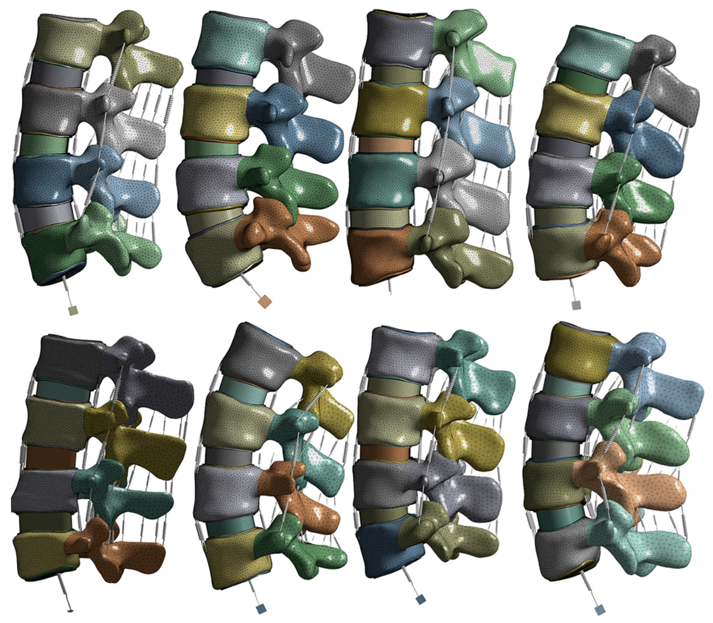
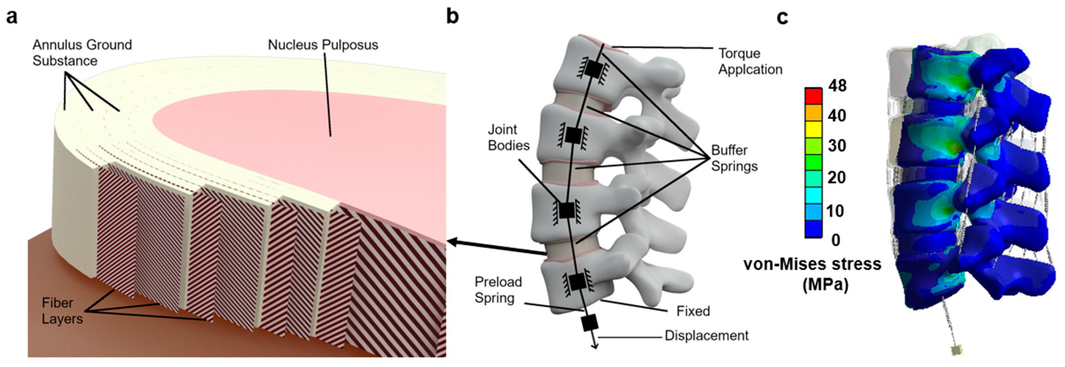
2.1. Model and Material
2.2. Boundary, Contact and Loading Conditions
2.3. Statistical Analysis
3. Results
3.1. Convergence
3.2. Intervertebral Rotation
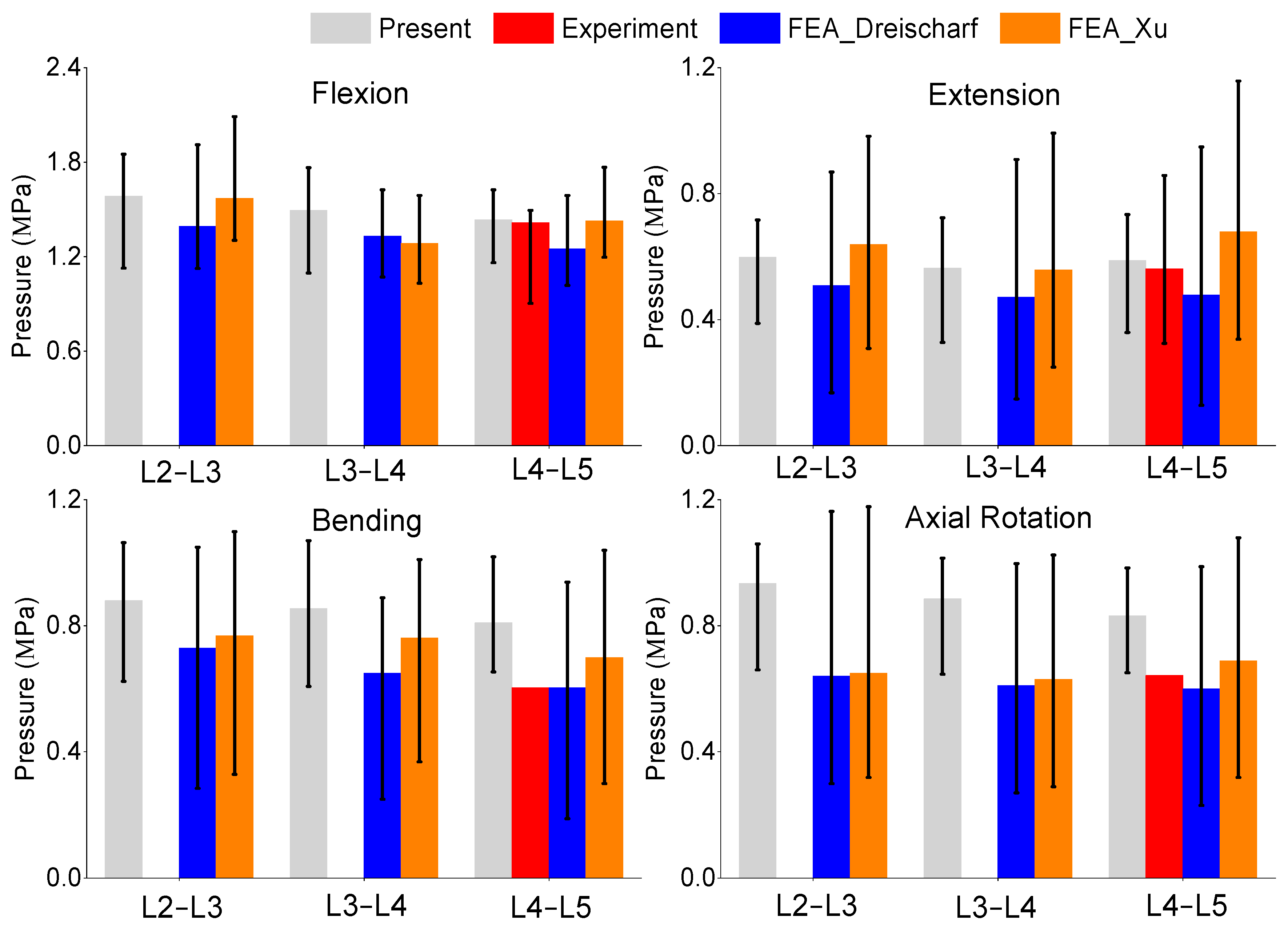
3.3. Pressure
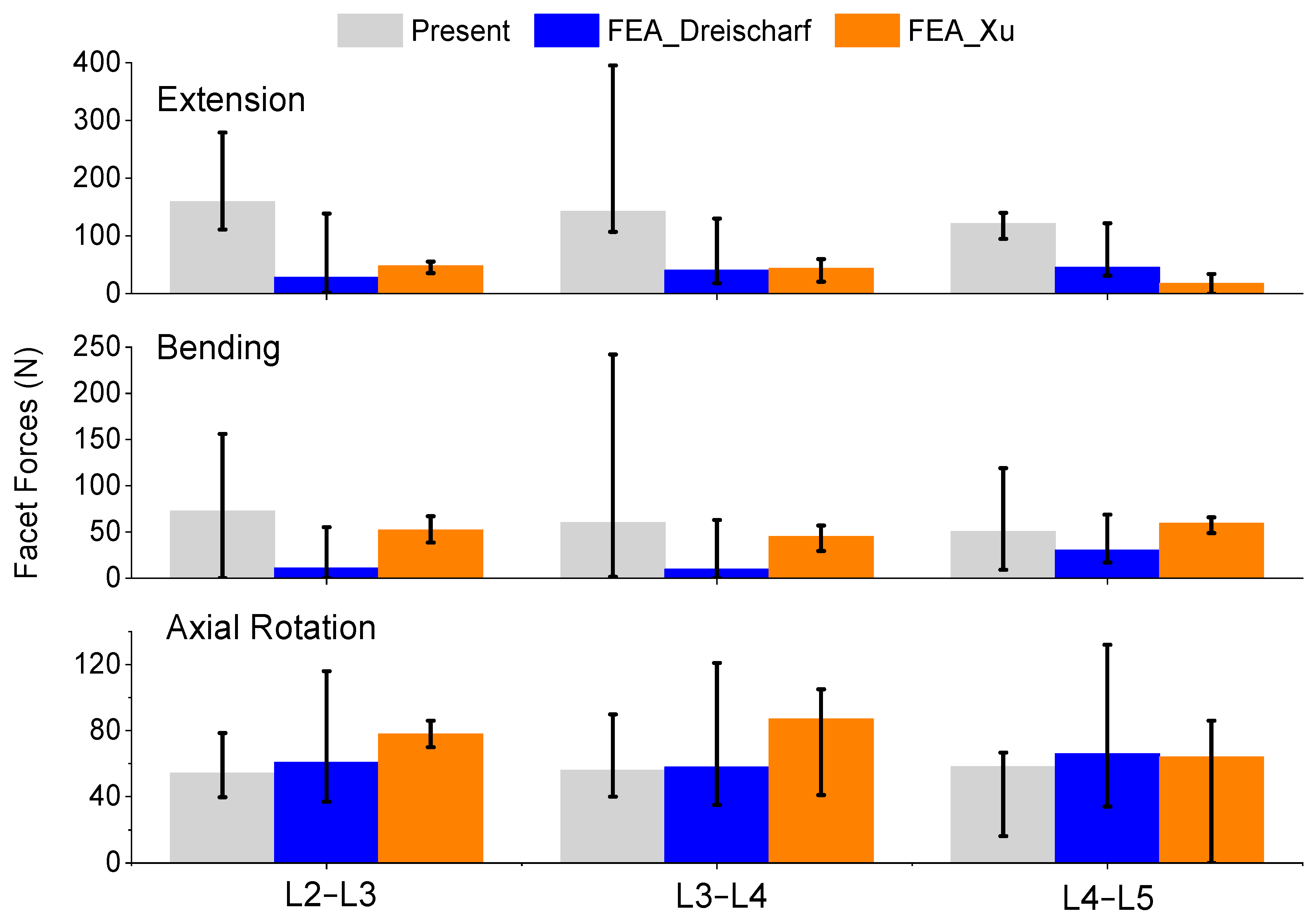
3.4. Facet Forces
3.5. Model Validation
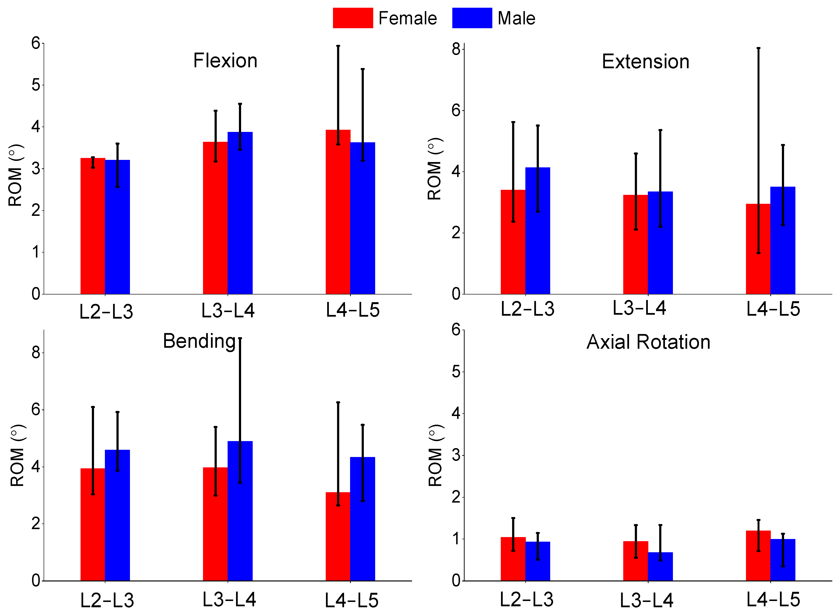
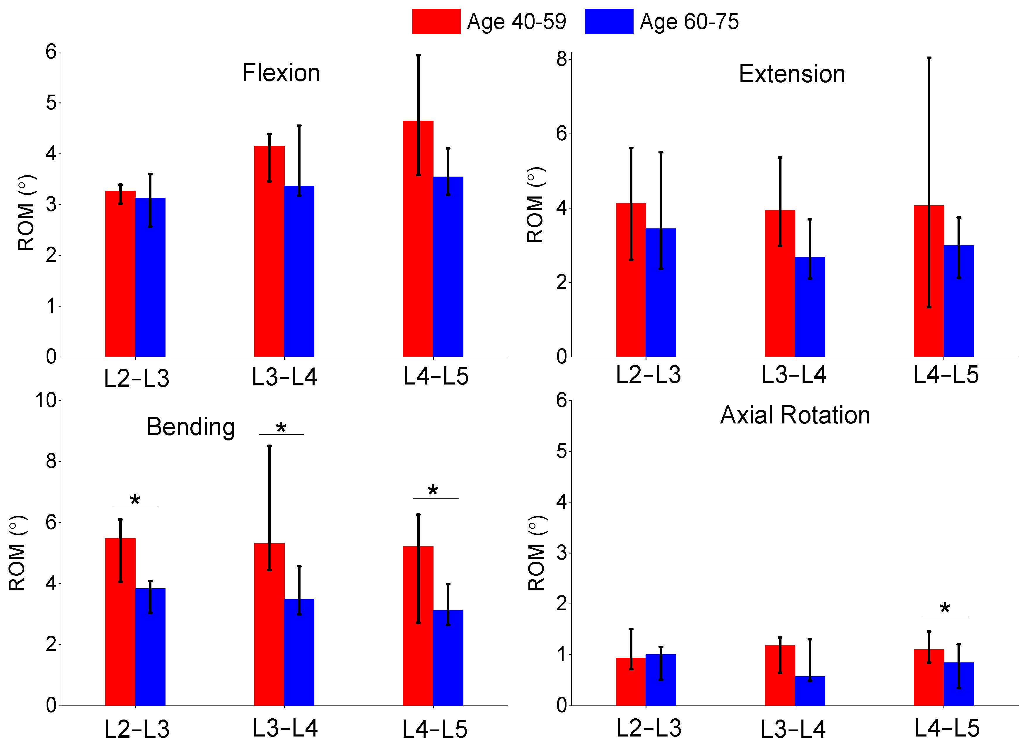
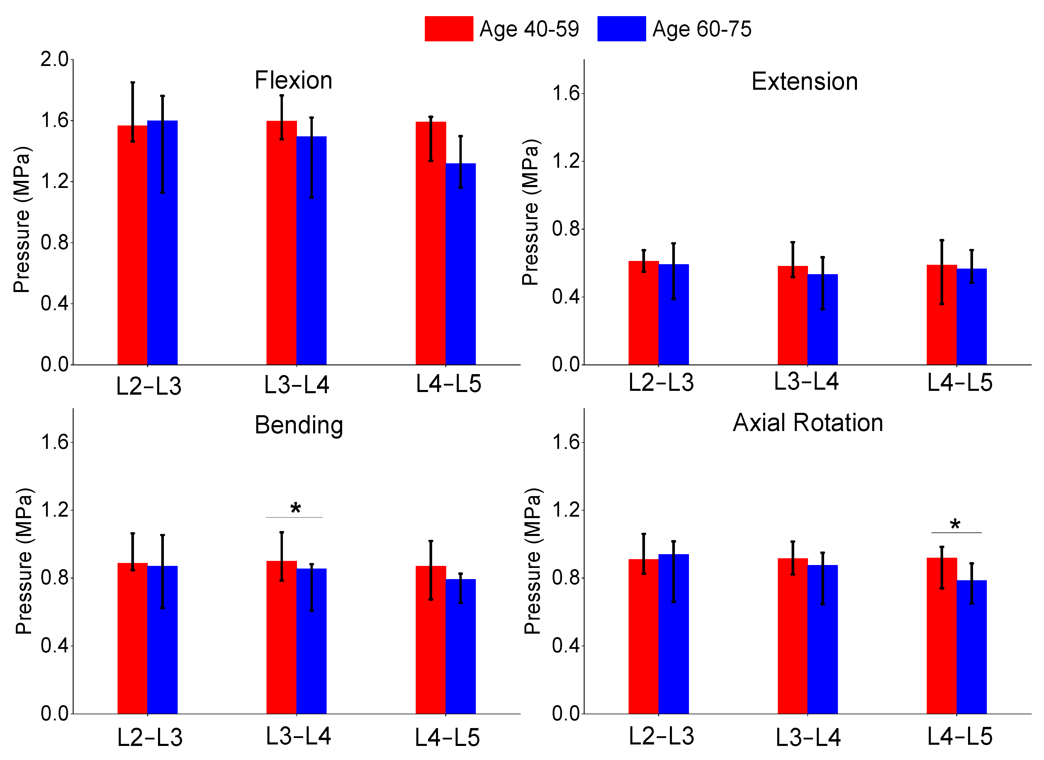
3.6. Age and Gender Comparison
4. Discussion
5. Conclusions
- The methodology produces reasonable representations of lumbar spine biomechanics and is suitable for comparative analyses.
- Future studies should investigate material and loading conditions.
- Spring elements are viable additions to lumbar spine finite element modeling.
- Multiple specimens are needed in lumbar spine finite element modeling to account for specimen variability.
- The age of the specimens had more noticeable differences compared to the gender in this study.
Author Contributions
Funding
Institutional Review Board Statement
Informed Consent Statement
Data Availability Statement
Conflicts of Interest
References
- Smith, C.; Lamba, N.; Ou, Z.; Vo, Q.-A.; Araujo-Lama, L.; Lim, S.; Joshi, D.; Doucette, J.; Papatheodorou, S.; Tafel, I. The prevalence of complications associated with lumbar and thoracic spinal deformity surgery in the elderly population: A meta-analysis. J. Spine Surg. 2019, 5, 223. [Google Scholar] [CrossRef] [PubMed]
- Cholewicki, J.; Breen, A.; Popovich, J.M., Jr.; Reeves, N.P.; Sahrmann, S.A.; Van Dillen, L.R.; Vleeming, A.; Hodges, P.W. Can biomechanics research lead to more effective treatment of low back pain? A point-counterpoint debate. J. Orthop. Sports Phys. Ther. 2019, 49, 425–436. [Google Scholar] [CrossRef] [PubMed]
- Lu, L.; Zhang, J.; Xie, Y.; Gao, F.; Xu, S.; Wu, X.; Ye, Z. Wearable health devices in health care: Narrative systematic review. JMIR Mhealth Uhealth 2020, 8, e18907. [Google Scholar] [CrossRef] [PubMed]
- Khuyagbaatar, B.; Kim, K.; Kim, Y.H. Recent developments in finite element analysis of the lumbar spine. Int. J. Precis. Eng. Manuf. 2023, 1–10. [Google Scholar] [CrossRef]
- Laubach, M.; Kobbe, P.; Hutmacher, D.W. Biodegradable interbody cages for lumbar spine fusion: Current concepts and future directions. Biomaterials 2022, 288, 121699. [Google Scholar] [CrossRef] [PubMed]
- Fisher, C.; Harty, J.; Yee, A.J.; Li, C.L.; Komolibus, K.; Grygoryev, K.; Lu, H.; Burke, R.; Wilson, B.C.; Andersson-Engels, S. Perspective on the integration of optical sensing into orthopedic surgical devices. J. Biomed. Opt. 2022, 27, 010601. [Google Scholar] [CrossRef] [PubMed]
- Tadano, S.; Tanabe, H.; Arai, S.; Fujino, K.; Doi, T.; Akai, M. Lumbar mechanical traction: A biomechanical assessment of change at the lumbar spine. BMC Musculoskelet. Disord. 2019, 20, 1–12. [Google Scholar] [CrossRef]
- Galbusera, F.; Niemeyer, F. Mathematical and finite element modeling. In Biomechanics of the Spine; Elsevier: Amsterdam, The Netherlands, 2018; pp. 239–255. [Google Scholar]
- Gierig, M.; Liu, F.; Weiser, L.; Lehmann, W.; Wriggers, P.; Marino, M.; Saul, D. biomechanical effects of a cross connector in sacral fractures–a finite element analysis. Biotechnology 2021, 9, 669321. [Google Scholar] [CrossRef]
- Pradeep, K.; Pal, B. Finite element analysis of an intact lumbar spine model: Effects of loading under different coordinate systems. Proc. Inst. Mech. Eng. Part H J. Eng. Med. 2023, 237, 09544119231177346. [Google Scholar] [CrossRef]
- Lin, M.; Doulgeris, J.; Dhar, U.K.; O’Corner, T.; Papanastassiou, I.D.; Tsai, C.-T.; Vrionis, F.D. Effect of graded posterior element and ligament removal on annulus stress and segmental stability in lumbar spine stenosis: A finite element analysis study. Front. Bioeng. Biotechnol. 2023, 11, 1237702. [Google Scholar] [CrossRef]
- Eberlein, R.; Holzapfel, G.A.; Fröhlich, M. Multi-segment FEA of the human lumbar spine including the heterogeneity of the annulus fibrosus. Comput. Mech. 2004, 34, 147–163. [Google Scholar] [CrossRef]
- Zhang, Z.; Fogel, G.R.; Liao, Z.; Sun, Y.; Liu, W. Biomechanical analysis of lumbar interbody fusion cages with various lordotic angles: A finite element study. Comput. Methods Biomech. Biomed. Eng. 2018, 21, 247–254. [Google Scholar] [CrossRef]
- Pawlikowski, M.; Domański, J.; Suchocki, C. Advanced finite element analysis of L4–L5 implanted spine segment. Contin. Mech. Thermodyn. 2015, 27, 571–582. [Google Scholar] [CrossRef]
- Dreischarf, M.; Zander, T.; Shirazi-Adl, A.; Puttlitz, C.M.; Adam, C.J.; Chen, C.S.; Goel, V.K.; Kiapour, A.; Kim, Y.H.; Labus, K.M.; et al. Comparison of eight published static finite element models of the intact lumbar spine: Predictive power of models improves when combined together. J. Biomech. 2014, 47, 1757–1766. [Google Scholar] [CrossRef]
- Lin, M.; Paul, R.; Liao, X.; Doulgeris, J.; Menzer, E.L.; Dhar, U.K.; Tsai, C.-T.; Vrionis, F.D. A New Method to Evaluate Pressure Distribution Using a 3D-Printed C2-C3 Cervical Spine Model with an Embedded Sensor Array. Sensors 2023, 23, 9547. [Google Scholar] [CrossRef]
- Lin, M.; Shapiro, S.Z.; Doulgeris, J.; Engeberg, E.D.; Tsai, C.T.; Vrionis, F.D. Cage-screw and anterior plating combination reduces the risk of micromotion and subsidence in multilevel anterior cervical discectomy and fusion-a finite element study. Spine J. 2021, 21, 874–882. [Google Scholar] [CrossRef]
- Lin, M.; Paul, R.; Shapiro, S.Z.; Doulgeris, J.; O’Connor, T.E.; Tsai, C.T.; Vrionis, F.D. Biomechanical Study of Cervical Endplate Removal on Subsidence and Migration in Multilevel Anterior Cervical Discectomy and Fusion. Asian Spine J. 2022, 16, 615–624. [Google Scholar] [CrossRef]
- Lin, M.; Shapiro, S.Z.; Engeberg, E.D.; Tsai, C.T.; Vrionis, F.D. Finite Element Analysis of the Effect of Dynamic Plating on Two-Level Anterior Cervical Discectomy Fusion Biomechanics. World Neurosurg. 2022, 163, e43–e52. [Google Scholar] [CrossRef]
- Lin, M.; Paul, R.; Dhar, U.K.; Doulgeris, J.; O’Connor, T.E.; Tsai, C.-T.; Vrionis, F.D. A Review of Finite Element Modeling for Anterior Cervical Discectomy and Fusion. Asian Spine J. 2023, 17, 94. [Google Scholar] [CrossRef]
- Lu, Y.M.; Hutton, W.C.; Gharpuray, V.M. Do bending, twisting, and diurnal fluid changes in the disc affect the propensity to prolapse? A viscoelastic finite element model. Spine 1996, 21, 2570–2579. [Google Scholar] [CrossRef]
- Meijer, G.J.; Homminga, J.; Veldhuizen, A.G.; Verkerke, G.J. Influence of interpersonal geometrical variation on spinal motion segment stiffness: Implications for patient-specific modeling. Spine 2011, 36, E929–E935. [Google Scholar] [CrossRef]
- Robin, S.; Skalli, W.; Lavaste, F. Influence of geometrical factors on the behavior of lumbar spine segments: A finite element analysis. Eur. Spine J. 1994, 3, 84–90. [Google Scholar] [CrossRef]
- Gonzalez-Blohm, S.A.; Doulgeris, J.J.; Lee, W.E.; Shea, T.M.; Aghayev, K.; Vrionis, F.D. The Current Testing Protocols for Biomechanical Evaluation of Lumbar Spinal Implants in Laboratory Setting: A Review of the Literature. BioMed Res. Int. 2015, 2015, 506181. [Google Scholar] [CrossRef]
- Xu, M.; Yang, J.; Lieberman, I.H.; Haddas, R. Lumbar spine finite element model for healthy subjects: Development and validation. Comput. Methods Biomech. Biomed. Eng. 2017, 20, 1–15. [Google Scholar] [CrossRef]
- Kim, H.-J.; Kang, K.-T.; Chang, B.-S.; Lee, C.-K.; Kim, J.-W.; Yeom, J.S. Biomechanical Analysis of Fusion Segment Rigidity Upon Stress at Both the Fusion and Adjacent Segments: A Comparison between Unilateral and Bilateral Pedicle Screw Fixation. Yonsei Med. J. 2014, 55, 1386. [Google Scholar] [CrossRef]
- Wilke, H.-J.; Rohlmann, A.; Neller, S.; Graichen, F.; Claes, L.; Bergmann, G. ISSLS Prize Winner: A Novel Approach to Determine Trunk Muscle Forces During Flexion and Extension: A Comparison of Data From an: In Vitro: Experiment and: In Vivo: Measurements. Spine 2003, 28, 2585–2593. [Google Scholar] [CrossRef]
- Rohlmann, A.; Zander, T.; Rao, M.; Bergmann, G. Realistic loading conditions for upper body bending. J. Biomech. 2009, 42, 884–890. [Google Scholar] [CrossRef]
- Panjabi, M.M.; Goel, V.; Oxland, T.; Takata, K.; Duranceau, J.; Krag, M.; Price, M. Human lumbar vertebrae. Quantitative three-dimensional anatomy. Spine 1992, 17, 299–306. [Google Scholar] [CrossRef]
- Goel, V.K.; Kong, W.; Han, J.S.; Weinstein, J.N.; Gilbertson, L.G. A combined finite element and optimization investigation of lumbar spine mechanics with and without muscles. Spine 1993, 18, 1531–1541. [Google Scholar] [CrossRef]
- Schmidt, H.; Shirazi-Adl, A.; Galbusera, F.; Wilke, H.-J. Response analysis of the lumbar spine during regular daily activities—A finite element analysis. J. Biomech. 2010, 43, 1849–1856. [Google Scholar] [CrossRef]
- Schmidt, H.; Heuer, F.; Simon, U.; Kettler, A.; Rohlmann, A.; Claes, L.; Wilke, H.J. Application of a new calibration method for a three-dimensional finite element model of a human lumbar annulus fibrosus. Clin. Biomech. 2006, 21, 337–344. [Google Scholar] [CrossRef]
- Shirazi-Adl, A.; Ahmed, A.M.; Shrivastava, S.C. Mechanical response of a lumbar motion segment in axial torque alone and combined with compression. Spine 1986, 11, 914–927. [Google Scholar] [CrossRef]
- Pearcy, M.J. Stereo radiography of lumbar spine motion. Acta Orthop. Scand. Suppl. 1985, 212, 1–45. [Google Scholar] [CrossRef]
- Sato, K.; Kikuchi, S.; Yonezawa, T. In vivo intradiscal pressure measurement in healthy individuals and in patients with ongoing back problems. Spine 1999, 24, 2468–2474. [Google Scholar] [CrossRef]
- Wilke, H.; Neef, P.; Hinz, B.; Seidel, H.; Claes, L. Intradiscal pressure together with anthropometric data--a data set for the validation of models. Clin. Biomech. 2001, 16 (Suppl. S1), S111–S126. [Google Scholar] [CrossRef]
- Kang, K.-T.; Koh, Y.-G.; Son, J.; Yeom, J.S.; Park, J.-H.; Kim, H.-J. Biomechanical evaluation of pedicle screw fixation system in spinal adjacent levels using polyetheretherketone, carbon-fiber-reinforced polyetheretherketone, and traditional titanium as rod materials. Compos. Part B Eng. 2017, 130, 248–256. [Google Scholar] [CrossRef]
- Ke, S.; He, X.; Yang, M.; Wang, S.; Song, X.; Li, Z. The biomechanical influence of facet joint parameters on corresponding segment in the lumbar spine: A new visualization method. Spine J. 2021, 21, 2112–2121. [Google Scholar] [CrossRef]
- Niemeyer, F.; Wilke, H.J.; Schmidt, H. Geometry strongly influences the response of numerical models of the lumbar spine—A probabilistic finite element analysis. J. Biomech. 2012, 45, 1414–1423. [Google Scholar] [CrossRef]
- Korecki, C.L.; MacLean, J.J.; Iatridis, J.C. Dynamic compression effects on intervertebral disc mechanics and biology. Spine 2008, 33, 1403–1409. [Google Scholar] [CrossRef]
- Menon, R.G.; Zibetti, M.V.W.; Pendola, M.; Regatte, R.R. Measurement of Three-Dimensional Internal Dynamic Strains in the Intervertebral Disc of the Lumbar Spine with Mechanical Loading and Golden-Angle Radial Sparse Parallel-Magnetic Resonance Imaging. J. Magn. Reson. Imaging 2021, 54, 486–496. [Google Scholar] [CrossRef]
- Michalek, A.J.; Buckley, M.R.; Bonassar, L.J.; Cohen, I.; Iatridis, J.C. Measurement of local strains in intervertebral disc anulus fibrosus tissue under dynamic shear: Contributions of matrix fiber orientation and elastin content. J. Biomech. 2009, 42, 2279–2285. [Google Scholar] [CrossRef]
- Little, J.P.; Adam, C.J. Geometric sensitivity of patient-specific finite element models of the spine to variability in user-selected anatomical landmarks. Comput. Methods Biomech. Biomed. Eng. 2015, 18, 676–688. [Google Scholar] [CrossRef]


| Component | Material Properties | Reference |
|---|---|---|
| Cortical bone | E = 12,000 MPa ν = 0.30 | Xu et al. [25] |
| Posterior elements | E = 3500 MPa ν = 0.30 | Xu et al. [25] |
| Cancellous bone | E = 100 MPa | Xu et al. [25] |
| Endplates | E = 23.8 MPa ν = 0.40 | Xu et al. [25] |
| Annulus ground substance | Hyperelastic c1 = 0.56, c2 = 0.14 | Schmidt et al. [32] |
| Nucleus pulpous | Hyperelastic c1 = 0.12, c2 = 0.09 | Schmidt et al. [32] |
| Ligaments | Nonlinear stress–strain curves, tension only | Averaged values between Eberlein et al. [12] and Shirazi-Adl et al. [33] |
| ALL | CSA = 35 mm2 | |
| PLL | CSA = 15 mm2 | |
| FLA | CSA = 75 mm2 | |
| FCL | CSA = 50 mm2 | |
| TL | CSA = 8 mm2 | |
| ISL | CSA = 35 mm2 | |
| SSL | CSA = 30 mm2 | |
| Annulus fiber | Nonlinear stress–strain curves, tension only | Shirazi-Adl et al. [33] |
| Layer 1 and 2 (Innermost layer) | Elasticity ratio = 0.65 CSA = 0.20 mm2 | |
| Layer 3 and 4 | Elasticity ratio = 0.75 CSA = 0.20 mm2 | |
| Layer 5 and 6 | Elasticity ratio = 0.90 CSA = 0.20 mm2 | |
| Layer 7 and 8 (Outermost layer) | Elasticity ratio = 1.00 CSA = 0.20 mm2 |
| ALL/PLL/TLL/SSL | FLA | FCL | ISL | ||||
|---|---|---|---|---|---|---|---|
| Strain | Stress (MPa) | Strain | Stress (MPa) | Strain | Stress (MPa) | Strain | Stress (MPa) |
| 0 | 0 | 0 | 0 | 0 | 0 | 0 | 0 |
| 0.15 | 1 | 0.35 | 1 | 0.24 | 1 | 0.17 | 1 |
| 0.18 | 1.5 | 0.4 | 1.5 | 0.28 | 1.5 | 0.295 | 2 |
| 0.22 | 2.5 | 0.45 | 2.5 | 0.315 | 2.5 | 0.39 | 3 |
| 0.25 | 5 | 0.52 | 5 | 0.35 | 5 | 0.49 | 4 |
| 0.27 | 7.5 | 0.55 | 7.5 | 0.38 | 7.5 | 0.56 | 5 |
| 0.285 | 10 | 0.575 | 10 | 0.39 | 10 | 0.6 | 5.6 |
| Layers 1 and 2 | Layers 3 and 4 | Layer 5 and 6 | Layer 7 and 8 | |
|---|---|---|---|---|
| Strain | Stress (MPa) | |||
| 0 | 0 | 0 | 0 | 0 |
| 0.05 | 29.25 | 33.75 | 40.5 | 45 |
| 0.1 | 47.45 | 54.75 | 65.7 | 73 |
| 0.15 | 57.2 | 66 | 79.2 | 88 |
| 0.2 | 63.05 | 72.75 | 87.3 | 97 |
| 0.25 | 66.3 | 76.5 | 91.8 | 102 |
Disclaimer/Publisher’s Note: The statements, opinions and data contained in all publications are solely those of the individual author(s) and contributor(s) and not of MDPI and/or the editor(s). MDPI and/or the editor(s) disclaim responsibility for any injury to people or property resulting from any ideas, methods, instructions or products referred to in the content. |
© 2023 by the authors. Licensee MDPI, Basel, Switzerland. This article is an open access article distributed under the terms and conditions of the Creative Commons Attribution (CC BY) license (https://creativecommons.org/licenses/by/4.0/).
Share and Cite
Doulgeris, J.; Lin, M.; Lee, W.; Aghayev, K.; Papanastassiou, I.D.; Tsai, C.-T.; Vrionis, F.D. Inter-Specimen Analysis of Diverse Finite Element Models of the Lumbar Spine. Bioengineering 2024, 11, 24. https://doi.org/10.3390/bioengineering11010024
Doulgeris J, Lin M, Lee W, Aghayev K, Papanastassiou ID, Tsai C-T, Vrionis FD. Inter-Specimen Analysis of Diverse Finite Element Models of the Lumbar Spine. Bioengineering. 2024; 11(1):24. https://doi.org/10.3390/bioengineering11010024
Chicago/Turabian StyleDoulgeris, James, Maohua Lin, William Lee, Kamran Aghayev, Ioannis Dimitri Papanastassiou, Chi-Tay Tsai, and Frank D. Vrionis. 2024. "Inter-Specimen Analysis of Diverse Finite Element Models of the Lumbar Spine" Bioengineering 11, no. 1: 24. https://doi.org/10.3390/bioengineering11010024
APA StyleDoulgeris, J., Lin, M., Lee, W., Aghayev, K., Papanastassiou, I. D., Tsai, C.-T., & Vrionis, F. D. (2024). Inter-Specimen Analysis of Diverse Finite Element Models of the Lumbar Spine. Bioengineering, 11(1), 24. https://doi.org/10.3390/bioengineering11010024