Investigation of Degradation and Biocompatibility of Indirect 3D-Printed Bile Duct Stents

 ,
,
Abstract
:
1. Introduction
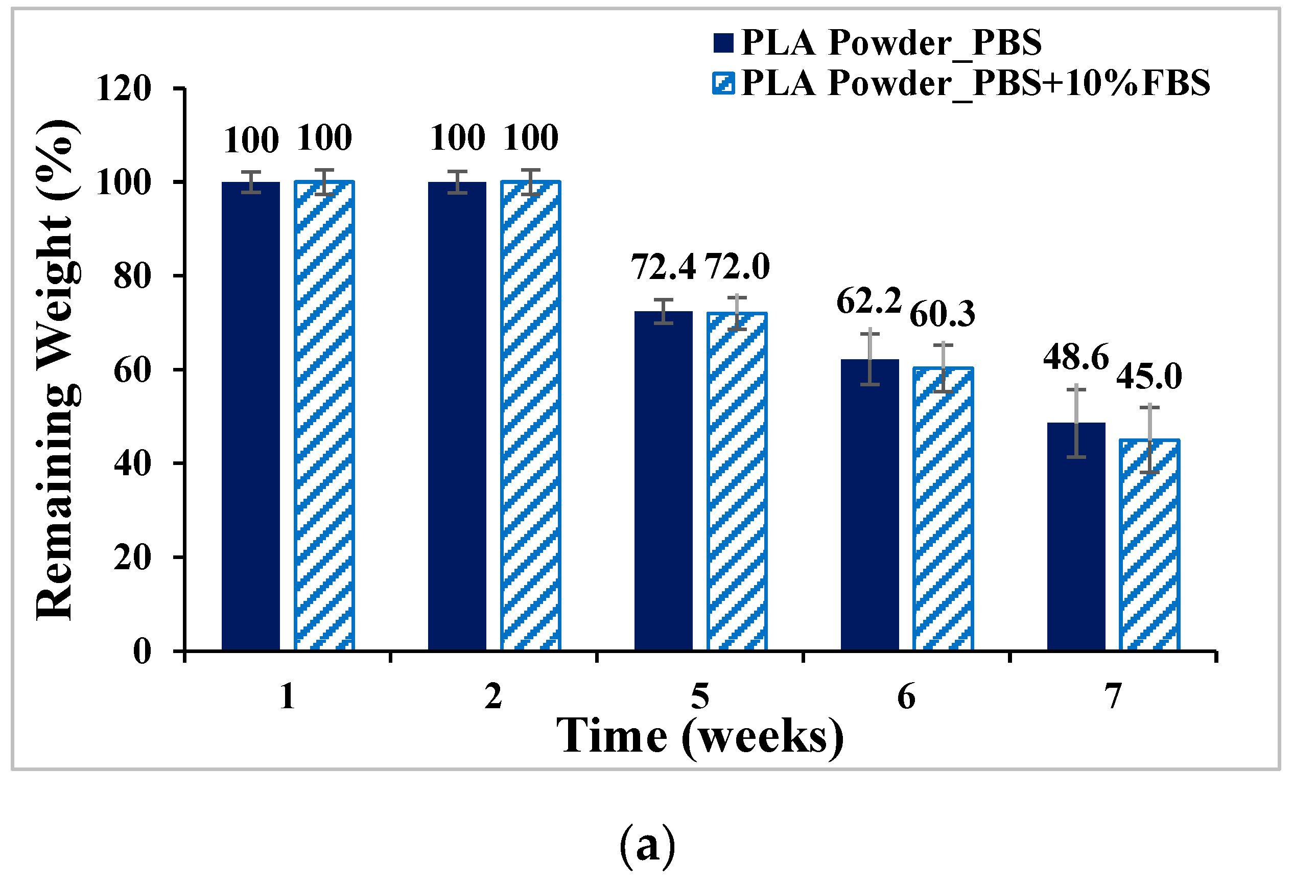
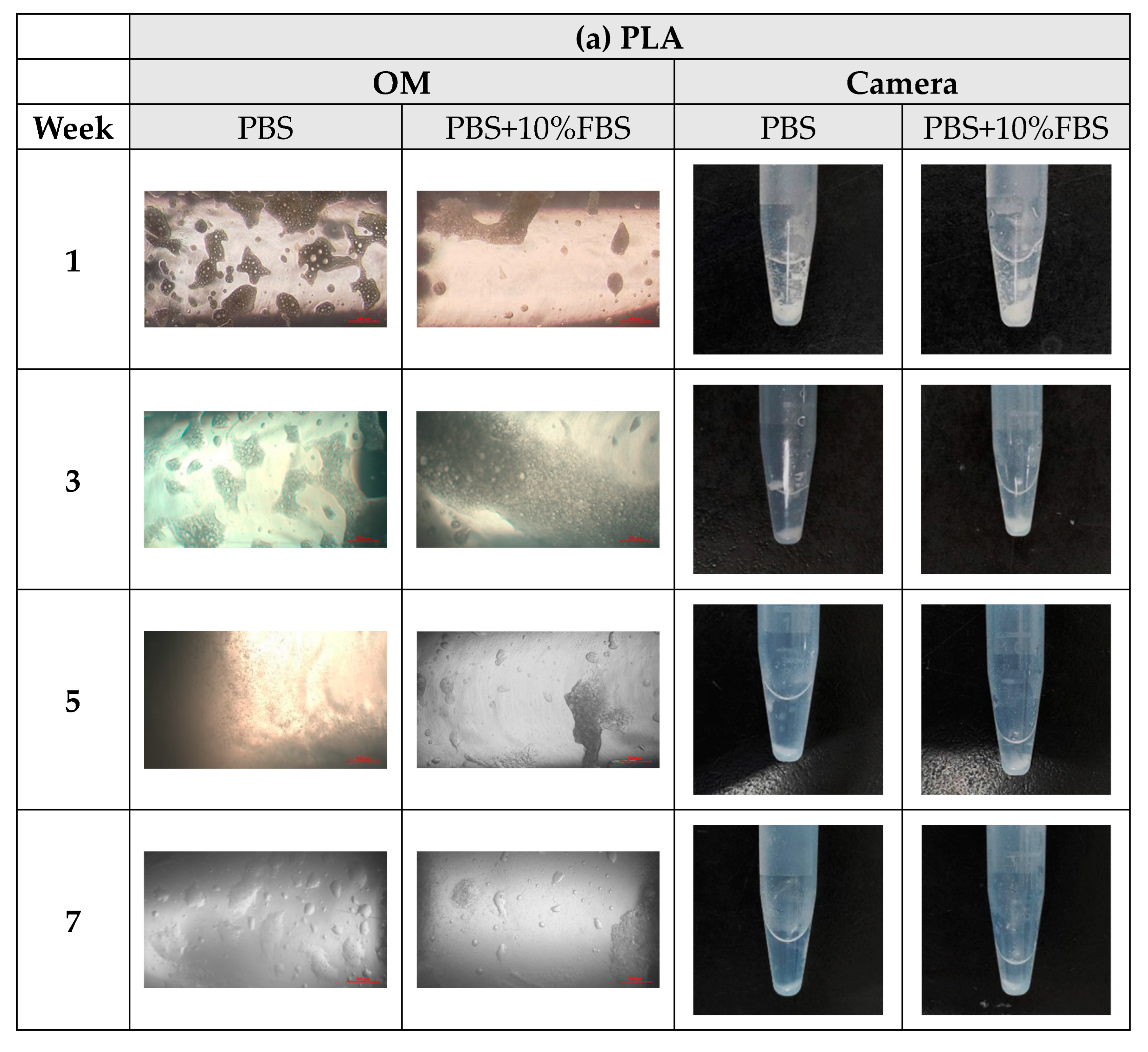
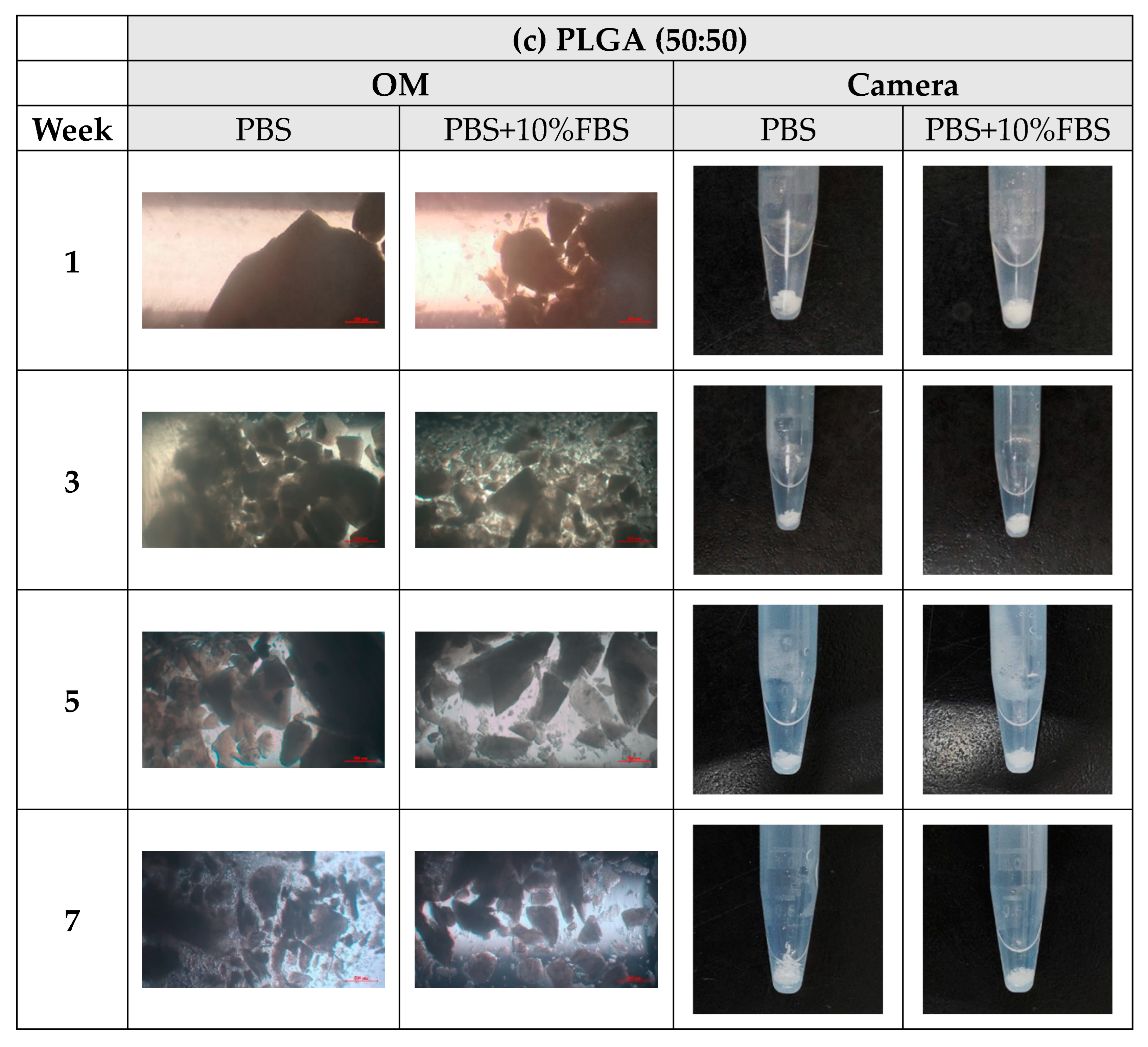
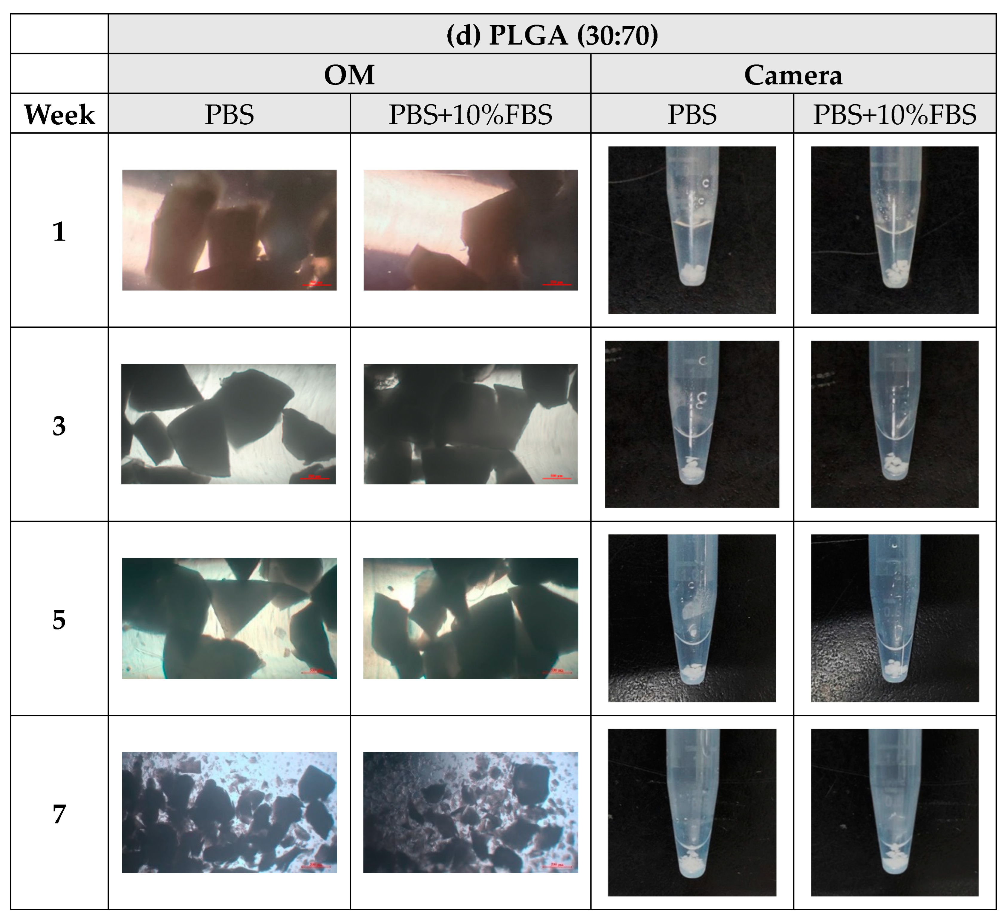
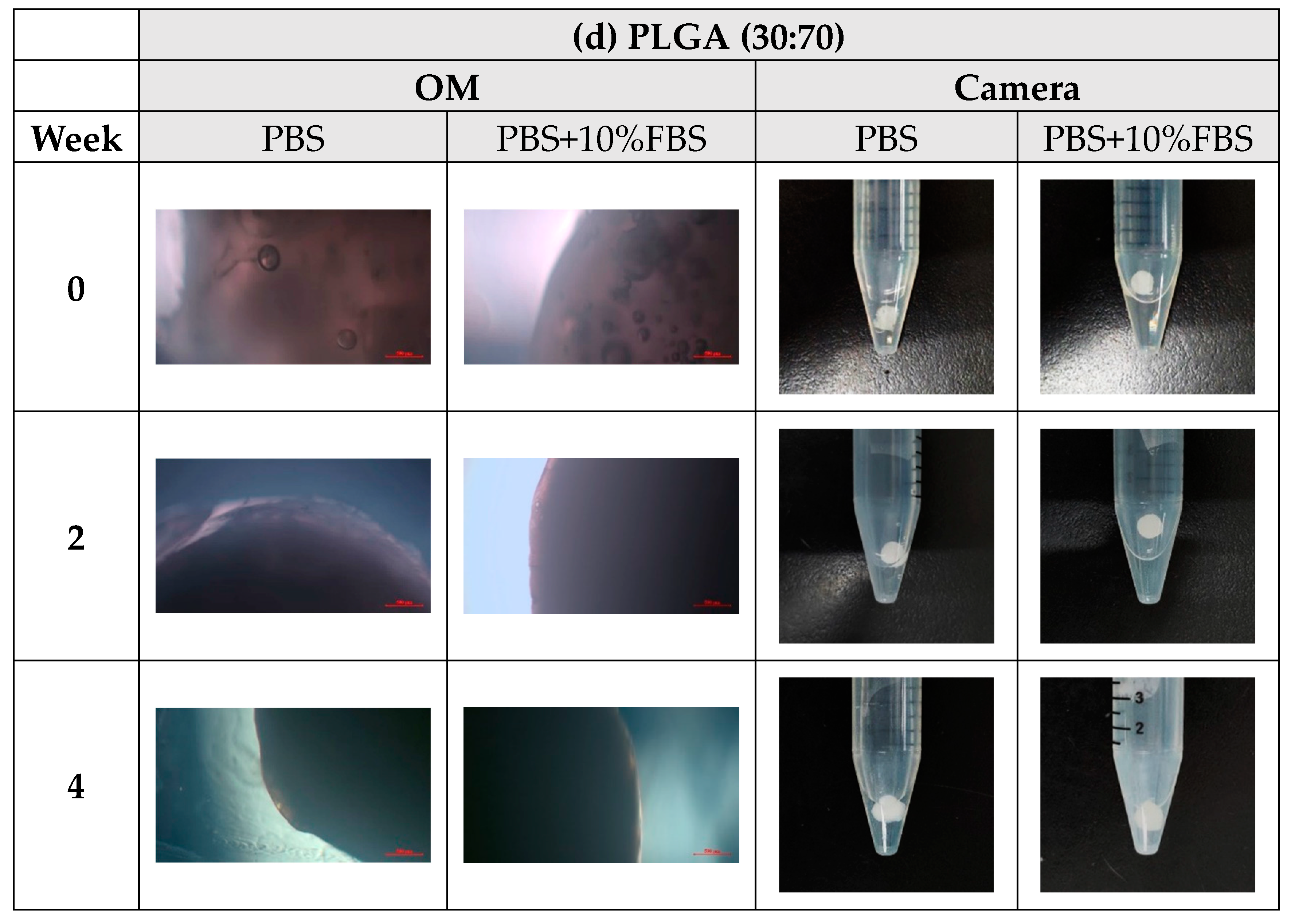
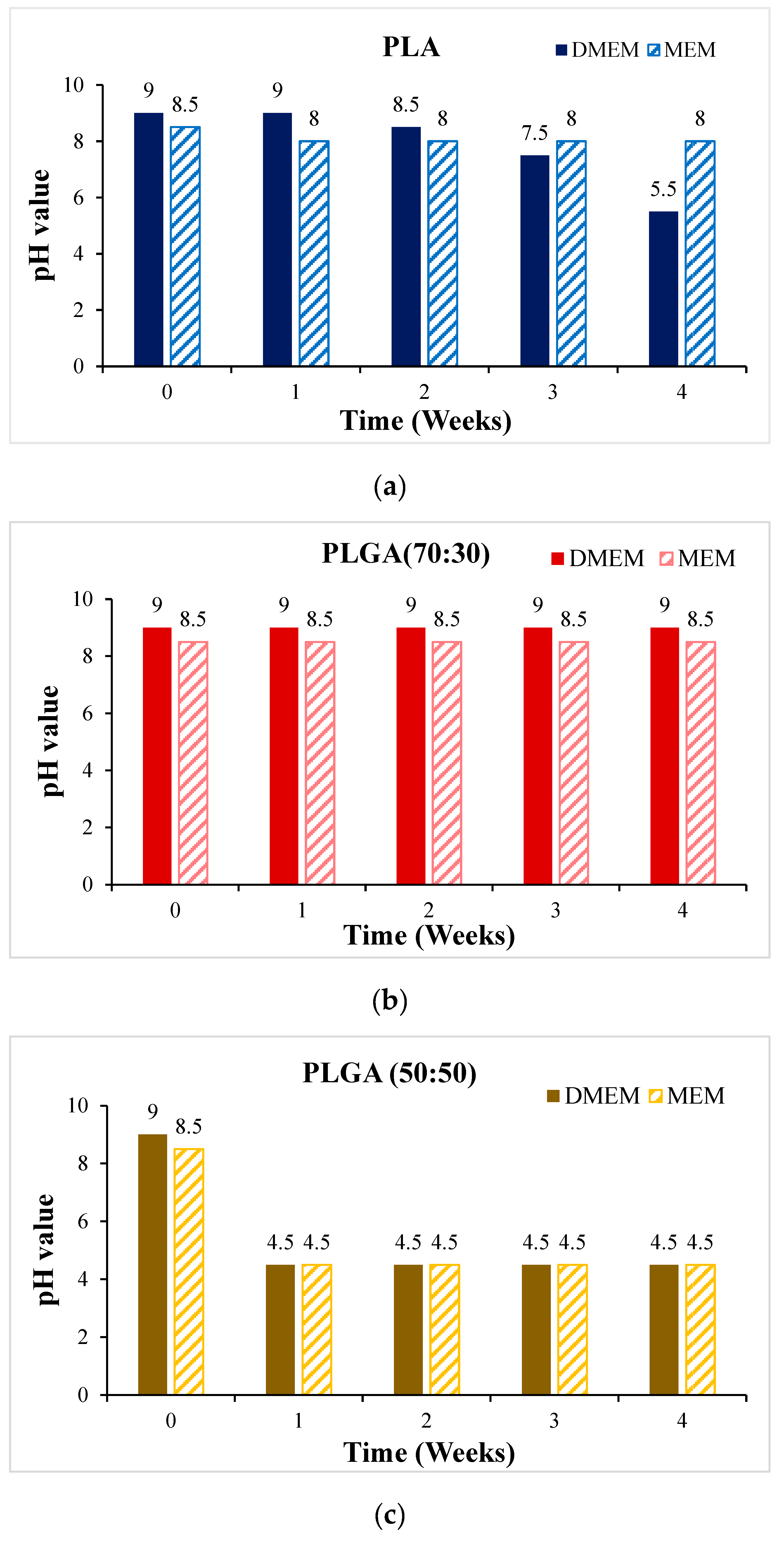
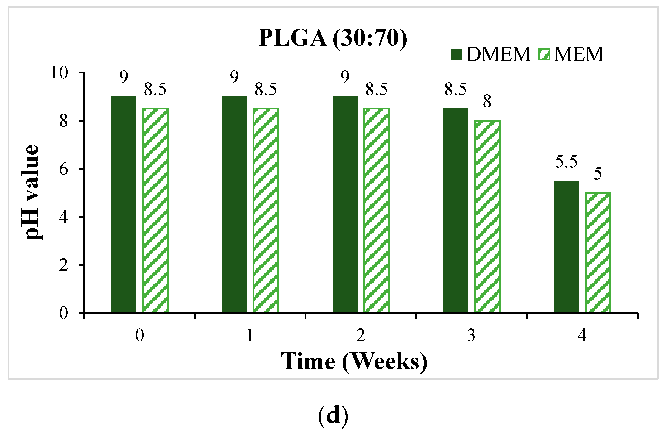
- In vitro degradation experiments of both powder and stent were conducted, and the degradation of powder and stent materials with different proportions was compared. In the powder degradation experiment, significant weight loss was observed in all four materials, meeting the conditions for material degradation within 4–6 weeks.
- Human liver cancer cells Hep-3B assessed the material’s biocompatibility and obtained preliminary test results. These served as the basis for the subsequent optimization of the scaffold.
2. Methods
2.1. Material Synthesis
- The GA monomer, LA monomer, and starting group (benzyl alcohol) were weighed and then vacuumed.
- The catalyst, tin-2-ethylhexanoate (0.0648 mL), was diluted with dry toluene (5 mL), and only 2.5 mL of this solution was used.
- The catalyst mixture was added to the monomers and the starting group. The toluene was drained after about 10 min, nitrogen (N2) was fed into the system, and the mixture was heated to 120–130 °C at 500 rpm to facilitate the reaction, followed by a purification process.
- For purification, the material was dissolved in dichloromethane (DCM), then crystallized and precipitated using methanol as an auxiliary material. It required maintaining a low temperature for 2–3 days before filtering out the sediment.
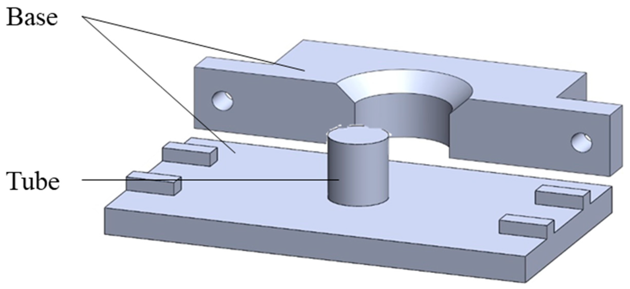
2.2. Stent Manufacturing Process
2.3. In Vitro Degradation Experiment
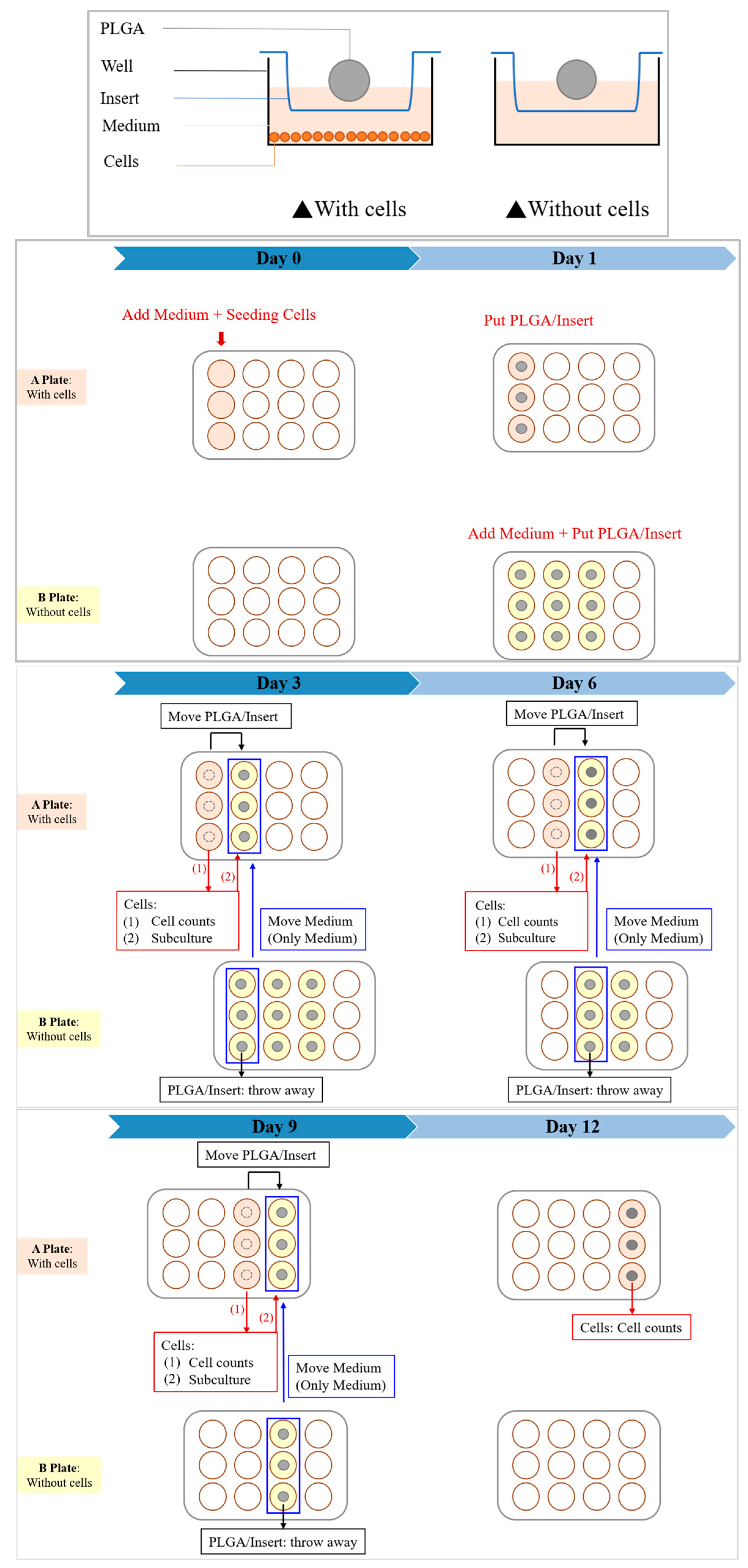
2.4. In Vitro Cytotoxicity Test
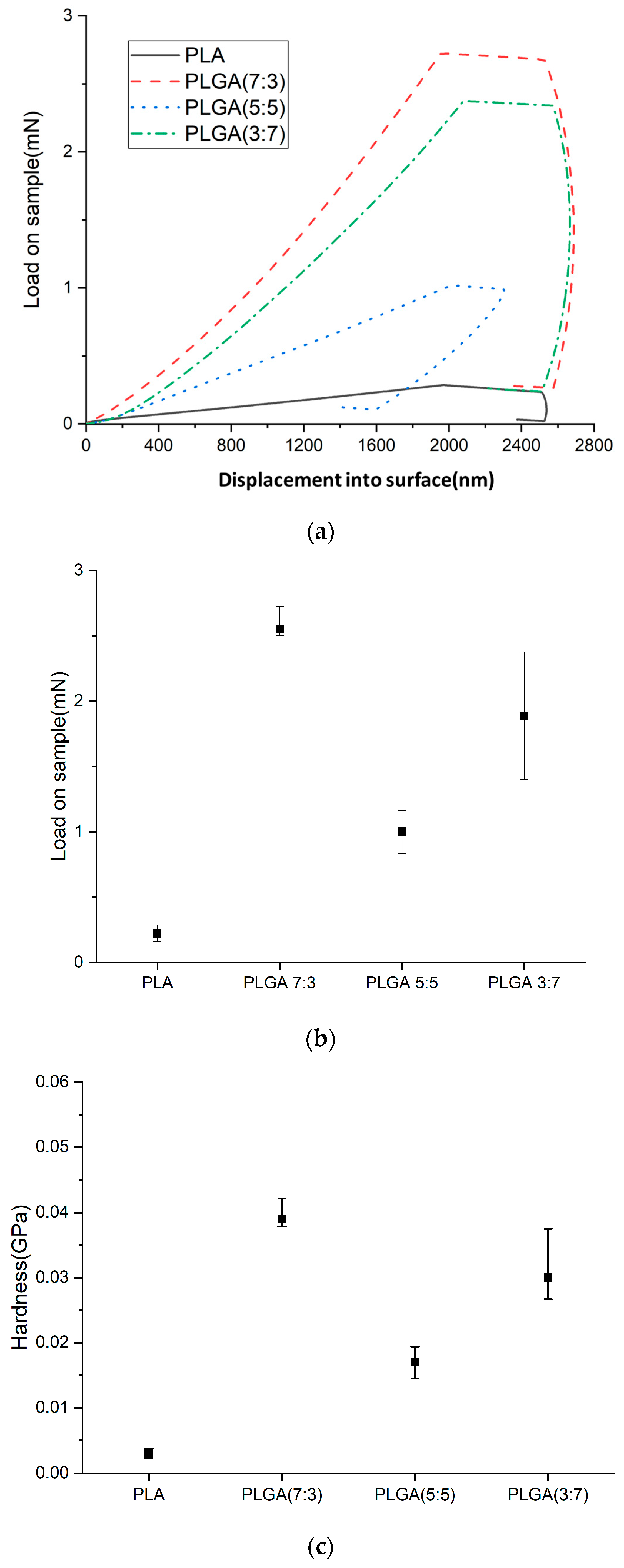
2.5. Nano-Indenter Testing System
- Hardness (H)
- 1.
- Load–displacement curve: During the test, a known force (load) is applied to an indenter as it presses into the material’s surface. The displacement of the indenter tip into the material is recorded, creating a load–displacement curve.
- 2.
- Maximum load: The curve identifies the maximum force applied during the indentation (PMAX) and the corresponding displacement.
- 3.
- Contact area calculation: The indentation impression’s contact area (A) at maximum load is calculated. This depends on the geometry of the indenter tip (commonly a Berkovich or a spherical tip) and the depth of the indentation.
- 4.
- Hardness calculation: Hardness is defined as the material’s resistance to deformation under load. It is calculated using the formula:
- Young’s Modulus (E)
3. Results
3.1. Material Synthesis
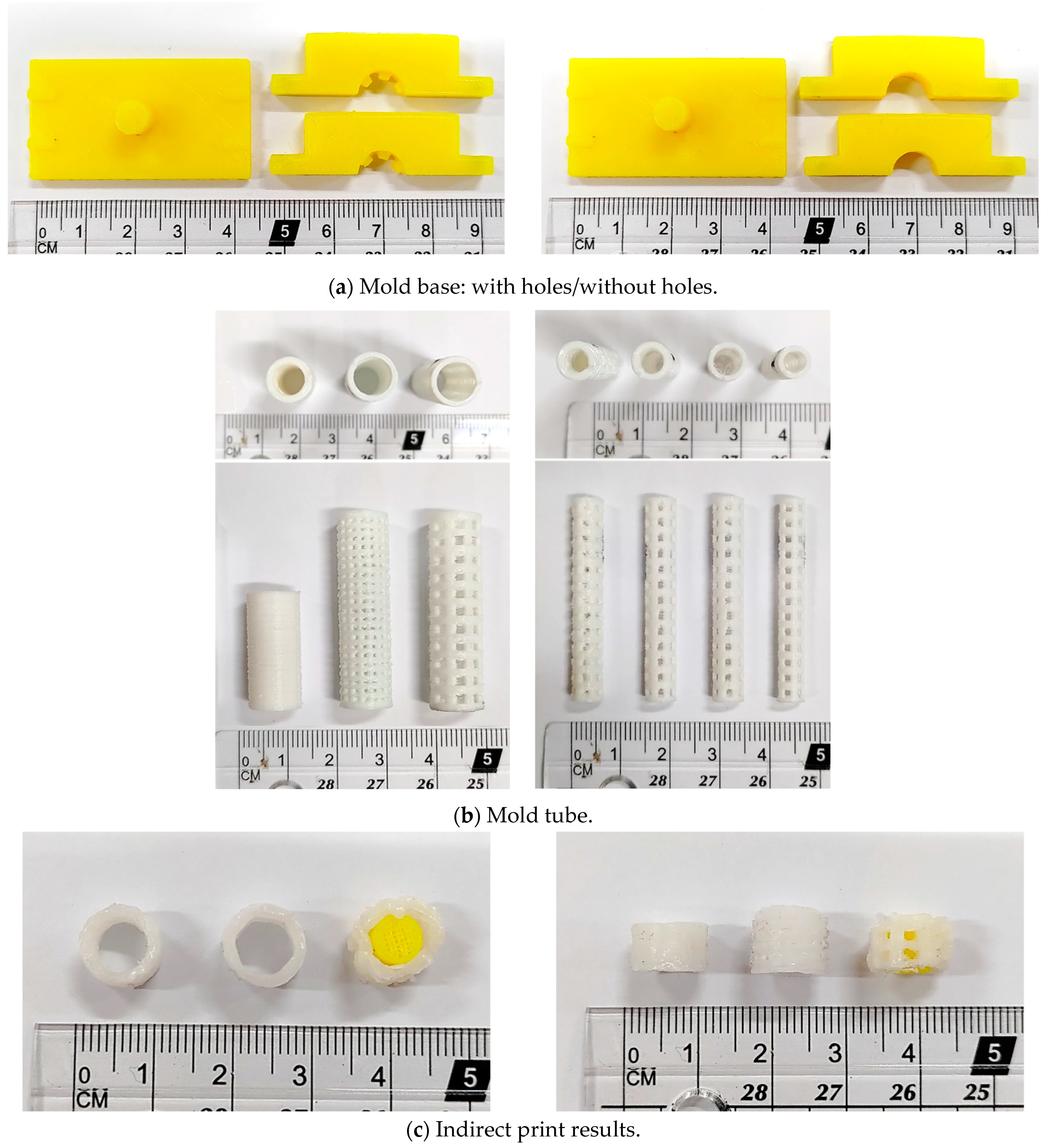
3.2. Stent Manufacturing Process
3.3. In Vitro Degradation Experiment
3.4. In Vitro Cytotoxicity Test
4. Conclusions
Author Contributions
Funding
Institutional Review Board Statement
Informed Consent Statement
Data Availability Statement
Conflicts of Interest
References
- MordorIntelligence. Global Medical Devices Market Size & Share Analysis—Growth Trends & Forecasts (2023–2028). 2023. Available online: https://www.mordorintelligence.com/industry-reports/global-medical-device-technologies-market-industry (accessed on 1 February 2023).
- Ministry of Health and Welfare of the Republic of China. Statistical Results of Causes of Death in the Republic of China in 2010. 2021. Available online: https://www.mohw.gov.tw/np-128-2.html (accessed on 18 June 2021).
- Health Promotion Administration of the Republic of China. Top 10 Cancer Rates; Health Promotion Administration of the Republic of China: Taipei, Taiwan, 2023. [Google Scholar]
- Schneider, J.; Duckworth-Mothes, B.; Schweizer, U.; Königsrainer, A.; Fisch, J.; Wichmann, D. Exerting Forces and Wall Load during Duodenoscopy for ERCP: An Experimental Measurement in an Artificial Model. Bioengineering 2023, 10, 523. [Google Scholar] [CrossRef] [PubMed]
- Li, F.; Zhu, Y.; Song, H.; Zhang, H.; Chen, L.; Guo, W. Analysis of Postoperative Remodeling Characteristics after Modular Inner Branched Stent-Graft Treatment of Aortic Arch Pathologies Using Computational Fluid Dynamics. Bioengineering 2023, 10, 164. [Google Scholar] [CrossRef]
- Kovács, N.; Pécsi, D.; Sipos, Z.; Farkas, N.; Földi, M.; Hegyi, P.; Bajor, J.; Erőss, B.; Márta, K.; Mikó, A.; et al. Suprapapillary Biliary Stents Have Longer Patency Times than Transpapillary Stents—A Systematic Review and Meta-Analysis. J. Clin. Med. 2023, 12, 898. [Google Scholar] [CrossRef] [PubMed]
- Shingwekar, D.; Laster, H.; Kemp, H.; Mellies, J.L. Two-Step Chemo-Microbial Degradation of Post-Consumer Polyethylene Terephthalate (PET) Plastic Enabled by a Biomass-Waste Catalyst. Bioengineering 2023, 10, 1253. [Google Scholar] [CrossRef] [PubMed]
- Bergman, J.J.; Burgemeister, L.; Bruno, M.J.; Rauws, E.A.; Gouma, D.J.; Tytgat, G.N.; Huibregtse, K. Long-term follow-up after biliary stent placement for postoperative bile duct stenosis. Gastrointest. Endosc. 2001, 54, 154–161. [Google Scholar] [CrossRef] [PubMed]
- ELLACS. DV Stent Biliary. Available online: https://ellacs.cz/en/dv-stent-biliary (accessed on 1 February 2023).
- Medtronic. Archimedes™* Biodegradable Biliary and Pancreatic Stent. Available online: https://www.medtronic.com/covidien/en-gb/products/therapeutic-endoscopy/archimedes-biliary-and-pancreatic-stent.html# (accessed on 1 February 2023).
- AmgInternational. UNITY-B Endoscopic Balloon Expandable Biodegradable Stent System. Available online: http://www.amggastro.com/unity-b.html (accessed on 1 February 2023).
- Park, S.-B.; Lih, E.; Park, K.-S.; Joung, Y.K.; Han, D.K. Biopolymer-based functional composites for medical applications. Prog. Polym. Sci. 2017, 68, 77–105. [Google Scholar] [CrossRef]
- Lal, N.; Mehra, S.; Lal, V. Ultrasonographic measurement of normal common bile duct diameter and its correlation with age, sex and anthropometry. J. Clin. Diagn. Res. 2014, 8, AC01–AC04. [Google Scholar] [CrossRef] [PubMed]
- Hedayati, S.K.; Behravesh, A.H.; Hasannia, S.; Saed, A.B.; Akhoundi, B. 3D printed PCL scaffold reinforced with continuous biodegradable fiber yarn: A study on mechanical and cell viability properties. Polym. Test. 2020, 83, 106347. [Google Scholar] [CrossRef]
- Liu, X.; Gao, J.; Cui, X.; Nie, S.; Wu, X.; Zhang, L.; Tang, P.; Liu, J.; Li, M. Functionalized 3D-Printed PLA Biomimetic Scaffold for Repairing Critical-Size Bone Defects. Bioengineering 2023, 10, 1019. [Google Scholar] [CrossRef]
- Misra, S.K.; Ostadhossein, F.; Babu, R.; Kus, J.; Tankasala, D.; Sutrisno, A.; Walsh, K.A.; Bromfield, C.R.; Pan, D. 3D-Printed Multidrug-Eluting Stent from Graphene-Nanoplatelet-Doped Biodegradable Polymer Composite. Adv. Healthc. Mater. 2017, 6, 1700008. [Google Scholar] [CrossRef]
- Hassanajili, S.; Karami-Pour, A.; Oryan, A.; Talaei-Khozani, T. Preparation and characterization of PLA/PCL/HA composite scaffolds using indirect 3D printing for bone tissue engineering. Mater. Sci. Eng. C 2019, 104, 109960. [Google Scholar] [CrossRef] [PubMed]
- Gao, J.; Chen, S.; Tang, D.; Jiang, L.; Shi, J.; Wang, S. Mechanical Properties and Degradability of Electrospun PCL/PLGA Blended Scaffolds as Vascular Grafts. Trans. Tianjin Univ. 2019, 25, 152–160. [Google Scholar] [CrossRef]
- Xu, X.; Liu, T.; Zhang, K.; Liu, S.; Shen, Z.; Li, Y.; Jing, X. Biodegradation of poly(l-lactide-co-glycolide) tube stents in bile. Polym. Degrad. Stab. 2008, 93, 811–817. [Google Scholar] [CrossRef]
- Bonartsev, A.P.; Boskhomodgiev, A.P.; Iordanskii, A.L.; Bonartseva, G.A.; Rebrov, A.V.; Makhina, T.K.; Myshkina, V.L.; Yakovlev, S.A.; Filatova, E.A.; Ivanov, E.A.; et al. Hydrolytic Degradation of Poly(3-hydroxybutyrate), Polylactide and their Derivatives: Kinetics, Crystallinity, and Surface Morphology. Mol. Cryst. Liq. Cryst. 2012, 556, 288–300. [Google Scholar] [CrossRef]
- Zhan, X.; Guo, X.; Liu, R.; Hu, W.; Zhang, L.; Xiang, N. Intervention using a novel biodegradable hollow stent containing polylactic acid-polyprolactone-polyethylene glycol complexes against lacrimal duct obstruction disease. PLoS ONE 2017, 12, e0178679. [Google Scholar] [CrossRef] [PubMed]
- Zilberman, M.; Nelson, K.D.; Eberhart, R.C. Mechanical properties andin vitro degradation of bioresorbable fibers and expandable fiber-based stents. J. Biomed. Mater. Res. Part B Appl. Biomater. 2005, 74, 792–799. [Google Scholar] [CrossRef] [PubMed]
- Ma, C.H.; Zhang, H.B.; Yang, S.M.; Yin, R.X.; Yao, X.J.; Zhang, W.J. Comparison of the degradation behavior of PLGA scaffolds in micro-channel, shaking, and static conditions. Biomicrofluidics 2018, 12, 034106. [Google Scholar] [CrossRef] [PubMed]
- Annaji, M.; Mita, N.; Poudel, I.; Boddu, S.H.S.; Fasina, O.; Babu, R.J. Three-Dimensional Printing of Drug-Eluting Implantable PLGA Scaffolds for Bone Regeneration. Bioengineering 2024, 11, 259. [Google Scholar] [CrossRef] [PubMed]
- Taewoong Niti-S™ D Biliary Stent. Available online: https://taewoongusa.com/products/niti-s-d-biliary-stent/ (accessed on 10 June 2024).
- WallFlex™ Biliary RX Stents. Available online: https://www.bostonscientific.com/en-US/products/stents--gastrointestinal/wallflex-biliary-rx-stents.html (accessed on 10 June 2024).
- Cotton-Leung® Biliary Stent Only. Available online: https://www.cookmedical.com/products/esc_clso_webds/ (accessed on 10 June 2024).
- Moy, B.T.; Birk, J.W. An update to hepatobiliary stents. J. Clin. Transl. Hepatol. 2015, 3, 67. [Google Scholar] [CrossRef] [PubMed]
- Isayama, H.; Nakai, Y.; Toyokawa, Y.; Togawa, O.; Gon, C.; Ito, Y.; Yashima, Y.; Yagioka, H.; Kogure, H.; Sasaki, T.; et al. Measurement of radial and axial forces of biliary self-expandable metallic stents. Gastrointest. Endosc. 2009, 70, 37–44. [Google Scholar] [CrossRef] [PubMed]


| LA Monomer | GA Monomer | |
|---|---|---|
| PLA | 15 g | -- |
| PLGA (70:30) | 10.5 g | 4.5 g |
| PLGA (50:50) | 7.5 g | 7.5 g |
| PLGA (30:70) | 4.5 g | 10.5 g |
| Material | PLA | PLGA (70:30) | PLGA (50:50) | PLGA (30:70) |
| Mn (g/mole) | 4000 | 16,000 | 16,000 | 16,000 |
| Appearance | 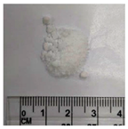 |  |  | 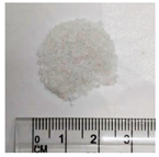 |
| Material | PLA | PLGA (70:30) | PLGA (50:50) | PLGA (30:70) |
| Temperature | 60–80 °C | 100–150 °C | 70–90 °C | 220–250 °C |
| Test record | 60 °C | 100 °C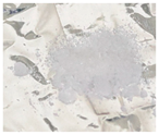 | 70 °C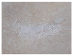 | 220 °C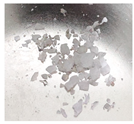 |
70 °C | 120 °C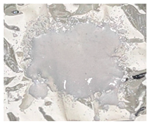 | 80 °C | 250 °C | |
80 °C | 150 °C | 90 °C | -- |
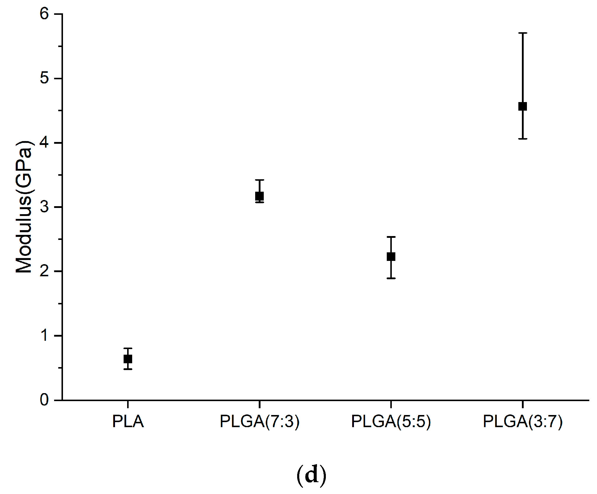
| Young’s Modulus (GPa) | Hardness (GPa) | |
|---|---|---|
| PLA | ||
| PLGA (7:3) | ||
| PLGA (5:5) | ||
| PLGA (3:7) |
Disclaimer/Publisher’s Note: The statements, opinions and data contained in all publications are solely those of the individual author(s) and contributor(s) and not of MDPI and/or the editor(s). MDPI and/or the editor(s) disclaim responsibility for any injury to people or property resulting from any ideas, methods, instructions or products referred to in the content. |
© 2024 by the authors. Licensee MDPI, Basel, Switzerland. This article is an open access article distributed under the terms and conditions of the Creative Commons Attribution (CC BY) license (https://creativecommons.org/licenses/by/4.0/).
Share and Cite
Lee, M.-C.; Pan, C.-T.; Huang, R.-J.; Ou, H.-Y.; Yu, C.-Y.; Shiue, Y.-L. Investigation of Degradation and Biocompatibility of Indirect 3D-Printed Bile Duct Stents. Bioengineering 2024, 11, 731. https://doi.org/10.3390/bioengineering11070731
Lee M-C, Pan C-T, Huang R-J, Ou H-Y, Yu C-Y, Shiue Y-L. Investigation of Degradation and Biocompatibility of Indirect 3D-Printed Bile Duct Stents. Bioengineering. 2024; 11(7):731. https://doi.org/10.3390/bioengineering11070731
Chicago/Turabian StyleLee, Ming-Chan, Cheng-Tang Pan, Ruo-Jiun Huang, Hsin-You Ou, Chun-Yen Yu, and Yow-Ling Shiue. 2024. "Investigation of Degradation and Biocompatibility of Indirect 3D-Printed Bile Duct Stents" Bioengineering 11, no. 7: 731. https://doi.org/10.3390/bioengineering11070731